Advertisement
I N S T A L L A T I O N
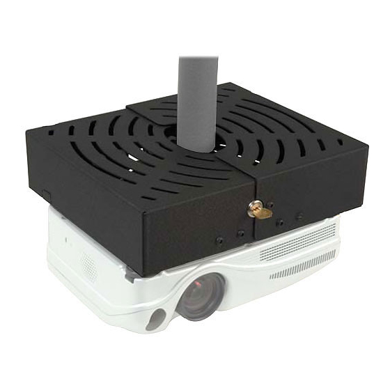
Projector
Lock
(PL-1)
The PL-1 projector lock, constructed with heavy gauge
steel, is designed to prevent access to projector mounts.
The projector lock protects against disconnecting
projectors from their mounts in most high-risk
environments, minimizing the probabilities theft.
The design of the PL-1 ensures proper ventilation for
your projector while providing excellent security and
protection.
BEFORE YOU BEGIN
•
CAUTION: To prevent damage to your display, which could affect or void the Factory warranty,
thoroughly study all instructions and illustrations before you begin to install the mount brackets. Pay
particular attention to the "Important Warnings and Cautions" on Page 2.
•
If you have any questions about this installation, contact Chief Manufacturing at 1-800-582-6480 or 952-582-6480.
CHIEF MANUFACTURING INC.
1-800-582-6480 952-894-6280 FAX 952-894-6918
8401 EAGLE CREEK PARKWAY, STE. 700
SAVAGE, MINNESOTA 55378 USA
I N S T R U C T I O N S
PL-1
8803-000065 (Rev. A)
©2005 Chief Manufacturing
www.chiefmfg.com
07/05
Advertisement
Table of Contents

Related Manuals for CHIEF PL-1


Summary of Contents for CHIEF PL-1
-
Page 1: Before You Begin
Pay particular attention to the “Important Warnings and Cautions” on Page 2. • If you have any questions about this installation, contact Chief Manufacturing at 1-800-582-6480 or 952-582-6480. CHIEF MANUFACTURING INC. 8803-000065 (Rev. A) 1-800-582-6480 952-894-6280 FAX 952-894-6918 ©2005 Chief Manufacturing... -
Page 2: Table Of Contents
Check the unit for shipping damage before you begin the installation. CAUTION CONTENTS TOOLS REQUIRED FOR TOOLS REQUIRED FOR INSTALLATION ..... 2 INSTALLATION DIMENSIONAL DRAWINGS .......... 3 PL-1 Drawing.............. 3 • Screw, 10-24x7/8” PPMS READ INSTRUCTIONS..........4 • Spacer, Nylon, .635ODx.194IDx.125 Thick INSPECT INSTALLATION LOCATION......4 INSTALLATION.............. -
Page 3: Dimensional Drawings
Installation Instructions PL-1 DIMENSIONAL DRAWINGS The dimensional drawings for the PL-1 are shown in Figure 1. PL-1 Drawing Figure 1. PL-1 Dimensions... -
Page 4: Read Instructions
5. Align set screw of RPA with key lock of cage (see Figure 2). 6. Tilt the lock side of the PL-1 down and route the RPA thru the hole in the PL-1 (see Figure 3). 7. Set PL-1 on RPA (see Figure 4). - Page 5 NOTE: Side cable knock outs may be removed if Figure 6. Replace Screws necessary. 14. Route the cables (see Figure 8). 15. Slide PL-1 halves together (see Figure 9). 16. Insert key. 17. Turn key 90 degrees clockwise. 18. Remove key.
Need help?
Do you have a question about the PL-1 and is the answer not in the manual?
Questions and answers