Table of Contents
Advertisement
Quick Links
I N S T A L L A T I O N I N S T R U C T I O N S
Instrucciones de instalación
Installationsanleitung
Instruções de Instalação
This device complies with part 15 of the FCC rules. Operation is subject to the following 2 conditions: (1) This device may not cause harmful
interference, and (2) this device must accept any interference received, including interference that may cause undesired operation.
This equipment has been tested and found to comply with the limits of a Class B digital device, pursuant to Part 15 of the FCC rules. These limits are
designed to provide reasonable protection against harmful interference in a residential installation. This equipment generates, uses and can radiate
radio frequency energy, and if not installed and used in accordance with the instructions, may cause harmful interference to radio or television
communications. However, there is no guarantee that the interference will not occur in a particular installation. If this equipment does cause harmful
interference to radio or television reception, which can be determined by turning the equipment off and on, the user is encouraged to try to correct
the interference by one of the following measures:
•
Reorient or relocate the receiving antenna
•
Increase the separation between the equipment and receiver
•
Connect the equipment to an outlet on a circuit other than that to which the receiver is connected
Consult the dealer or an experienced radio/TV technician for help
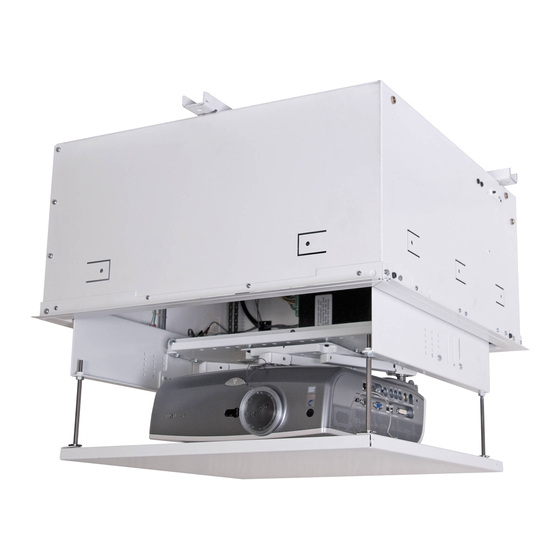
SMART-LIFT™ Electric Ceiling Lift
Istruzioni di installazione
Installatie-instructies
Instructions d´installation
SL151
Advertisement
Table of Contents

Subscribe to Our Youtube Channel
Related Manuals for CHIEF SMART-LIFT SL151


Summary of Contents for CHIEF SMART-LIFT SL151
- Page 1 I N S T A L L A T I O N I N S T R U C T I O N S Instrucciones de instalación Istruzioni di installazione Installationsanleitung Installatie-instructies Instruções de Instalação Instructions d´installation SMART-LIFT™ Electric Ceiling Lift This device complies with part 15 of the FCC rules.
-
Page 2: Disclaimer
• Keep the test power cord away from heated surfaces. Chief® is a registered trademark of Milestone AV Technologies. • Never operate the mounting system with the air All rights reserved. -
Page 3: Tools Required For Installation
Installation Instructions SL151 TOOLS REQUIRED FOR INSTALLATION PARTS A (1) [Ceiling Lift] D (1) [Push Button Assembly] C (1) B (5) [External Terminal [Cable Tie] Cover Plate] H (1) [Jumper Wire] F (4) G (2) E (5) 6-32 x 3/16 [Rubber Grommet] [Cable Tie Mount] LEGEND... -
Page 4: Table Of Contents
SL151 Installation Instructions DIMENSIONS [207.0] DIMENSIONS: [MILLIMETERS] 8.15 INCHES MAX PROJECTOR/EQUIPMENT SIZE: Height: 8.375" [212.7mm] Width: 18.25" [463.6mm] Length: 18.25" [463.6mm] Weight: 35# [15.9kg] [410.2] [596.9] 16.15 23.50 [578.6] 22.78 [413.8] SLOTS ACCOMMODATE 3/8" THREADED ROD 16.29 [596.9] [579.4] TERMINAL BLOCK & COVER MAY 23.50 22.81 BE REMOVED IF MAKING ALL... -
Page 5: Installation Requirements
Carefully inspect the SL151 for any shipping damage. If any damage is apparent, do NOT continue with the installation. Instead, contact Chief for further instructions. Place SL151 upside down on clean surface. (See Figure 1) Wire push button assembly (D) (1-red, 6-black) Figure 3 Plug in the SL151 test cord. -
Page 6: Removing Ceiling Panel
SL151 Installation Instructions WARNING: RISK OF ELECTROCUTION! All electrical Ceiling Panel Removed wiring required for installation should be installed by a qualified electrician. WARNING: PINCH HAZARD! FINGERS OR HANDS BETWEEN MOVING PARTS CAN LEAD TO SEVERE PERSONAL INJURY! Keep fingers and hands away from mount when operating. -
Page 7: Installing In A Wood Framework (Joists)
Installation Instructions SL151 Installing in a Wood Framework (Joists) Use 1/4" x 1-1/2" (minimum) Grade 2 lag screws (not provided) to secure SL151 to the joists or wood framework, using the mounting tabs located on the sides of the SL151 housing. -
Page 8: Connecting Control Wiring
SL151 Installation Instructions Connecting Control Wiring WARNING: All wiring should be performed by a licensed electrician following all local codes and ordinances. Unplug the SL151’s test cord (used for testing). Remove the jumper wire and supplied push button wiring (previously installed in the Pre-Test Lift before Installation section) from the external terminal block. -
Page 9: Wiring Options
Installation Instructions SL151 NOTE: If installing the SL151 in a drywall ceiling, remove the outside terminal block and cover with plate (C), using four 6-32 x 3/16" Phillips pan head screws (F). Wiring Options NOTE: Refer to Table 1: Wiring Table and (See Figure 16) for information on all wiring options. - Page 10 SL151 Installation Instructions Table 1: WIRING TABLE INTERNAL EXTERNAL WIRING WIRING Figure 16 NOTE: The numbers listed in the SL151 Internal and SL151 External columns refer to the corresponding numbers located where indicated in the wiring pictures. (See Figure 16)
- Page 11 Installation Instructions SL151 Table 2: INTERNAL TERMINAL DESCRIPTIONS...
-
Page 12: Descriptions
SL151 Installation Instructions Figure 17... - Page 13 Installation Instructions SL151...
- Page 14 SL151 Installation Instructions...
- Page 15 Installation Instructions SL151...
- Page 16 A 8401 Eagle Creek Parkway, Savage, MN 55378 P 800.582.6480 / 952.894.6280 F 877.894.6918 / 952.894.6918 Europe A Fellenoord 130 5611 ZB EINDHOVEN, The Netherlands Chief Manufacturing, a products division P +31 (0)40 2668620 of Milestone AV Technologies F +31 (0)40 2668615 Asia Pacific A Office No.
Need help?
Do you have a question about the SMART-LIFT SL151 and is the answer not in the manual?
Questions and answers