Advertisement
Quick Links
Instruction Manual
DVI Video Extender over CAT5 UTP
ST121UTPDVI / ST121UTPDVGB / ST121UTPDVEU
DE: Bedienungsanleitung - de.startech.com
FR: Guide de l'utilisateur - fr.startech.com
ES: Guía del usuario - es.startech.com
IT: Guida per l'uso - it.startech.com
NL: Gebruiksaanwijzing - nl.startech.com
PT: Guia do usuário - pt.startech.com
Packaging Contents
• 1 x DVI Extender Local Unit
• 1 x DVI Extender Remote Unit
• 2 x Power Adapter
• 1 x Instruction Manual
System Requirements
• DVI enabled video source device (i.e. computer, PVR/DVR, etc)
• DVI enabled video display device (i.e. monitor, projector, etc)
• Available AC electrical out at local/remote locations
Preparing Your Site
1. Determine where the local video source (i.e. computer) will be
located and set up the device.
2. Determine where the remote display will be located and place/
mount the display appropriately.
3. If you are using surface cabling, ensure you have enough Cat5
unshielded twisted pair (UTP) Ethernet cabling to connect the
Local Unit to the Remote Unit's location, and that each end is
terminated with a RJ45 Ethernet connector. The cabling should not
go through any networking equipment (i.e. router, switch).
OR
If you are using premise cabling, ensure that the Cat5 unshielded
twisted pair (UTP) Ethernet Cabling between the Local Unit and
the Remote Unit has been properly terminated in a wall outlet in
each location and there is a patch cable long enough to connect
the Remote Unit and the Local Unit to their respective outlets. The
cabling should not go through any networking equipment (i.e.
router, switch).
For the most up-to-date information, please visit: www.startech.com
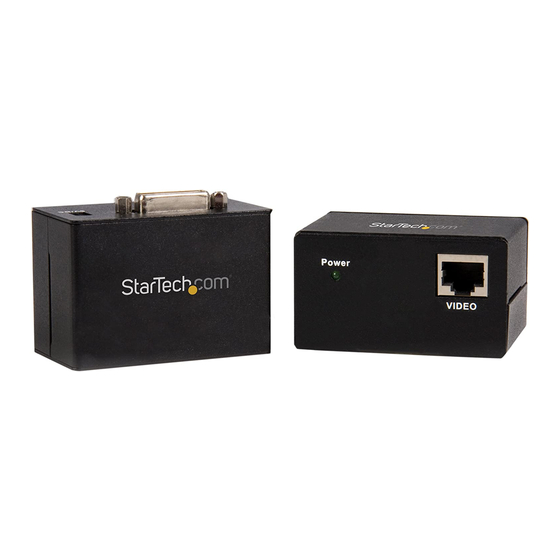
Local Unit
Remote Unit
Installation
1. Turn off the video source (i.e. computer) and the intended display
device (i.e. monitor).
2. Position the Remote Unit near the intended display.
3. Position the Local Unit near the video source.
Please note that both units will require a power connection, so
please ensure that each unit is situated near an available power
outlet.
4. Connect the video source to the "DVI In" port on the rear panel of
the Local Unit, using a DVI-D male/male cable.
5. Connect the intended display to the "DVI Out" port located on the
rear panel of the Remote Unit using a DVI-D male/male cable.
6. Connect the Local Unit to the Remote Unit, using standard RJ45
terminated CAT5 cable (see Preparing Your Site).
7. Connect the power adapters (provided) to both Local and Remote
Units.
8. Turn on the display device first, followed by the video source.
Manual Revision: 02/07/2012
Advertisement

Subscribe to Our Youtube Channel
Related Manuals for StarTech.com ST121UTPDVI


Summary of Contents for StarTech.com ST121UTPDVI
-
Page 1: Instruction Manual
2. Determine where the remote display will be located and place/ 2. Position the Remote Unit near the intended display. mount the display appropriately. 3. Position the Local Unit near the video source. Please note that both units will require a power connection, so 3. If you are using surface cabling, ensure you have enough Cat5 unshielded twisted pair (UTP) Ethernet cabling to connect the please ensure that each unit is situated near an available power Local Unit to the Remote Unit’s location, and that each end is outlet. terminated with a RJ45 Ethernet connector. The cabling should not 4. Connect the video source to the “DVI In” port on the rear panel of go through any networking equipment (i.e. router, switch). the Local Unit, using a DVI-D male/male cable. 5. Connect the intended display to the “DVI Out” port located on the If you are using premise cabling, ensure that the Cat5 unshielded rear panel of the Remote Unit using a DVI-D male/male cable. twisted pair (UTP) Ethernet Cabling between the Local Unit and 6. Connect the Local Unit to the Remote Unit, using standard RJ45 the Remote Unit has been properly terminated in a wall outlet in terminated CAT5 cable (see Preparing Your Site). each location and there is a patch cable long enough to connect 7. Connect the power adapters (provided) to both Local and Remote the Remote Unit and the Local Unit to their respective outlets. The Units. cabling should not go through any networking equipment (i.e. 8. Turn on the display device first, followed by the video source. router, switch). For the most up-to-date information, please visit: www.startech.com Manual Revision: 02/07/2012... -
Page 2: Wiring Diagram
• Consult the dealer or an experienced radio/TV technician for help. Use of Trademarks, Registered Trademarks, and other Protected Names and Symbols This manual may make reference to trademarks, registered trademarks, and other protected names and/or symbols of third-party companies not related in any way to StarTech.com. Where they occur these references are for illustrative purposes only and do not represent an endorsement of a product or service by StarTech.com, or an endorsement of the product(s) to which this manual applies by the third-party company in question. Regardless of any direct acknowledgement elsewhere in the body of this document, StarTech.com hereby acknowledges that all trademarks, registered trademarks, service marks, and other protected names and/or symbols contained in this manual and related documents are the property of their respective holders.
Need help?
Do you have a question about the ST121UTPDVI and is the answer not in the manual?
Questions and answers