Table of Contents
Advertisement
Instruction Manual
DXLink
Twisted Pair
™
Transmitters/Receiver
DXLink Multi-Format Wallplate Transmitter
DXLink Multi-Format Decor Style Wallplate Transmitter (US)
DXLink Multi-Format Transmitter Module
DXLink HDMI Transmitter Module
DXLink HDMI Receiver Module
D X L i n k ™ T w i s t e d P a i r T r a n s m i t t e r s / R e c e i v e r
R EV L : 1 0 / 0 8 / 2 0 1 3
Advertisement
Table of Contents

Related Manuals for AMX DXLink Multi-Format Wallplate


Summary of Contents for AMX DXLink Multi-Format Wallplate
- Page 1 Instruction Manual DXLink Twisted Pair ™ Transmitters/Receiver DXLink Multi-Format Wallplate Transmitter DXLink Multi-Format Decor Style Wallplate Transmitter (US) DXLink Multi-Format Transmitter Module DXLink HDMI Transmitter Module DXLink HDMI Receiver Module D X L i n k ™ T w i s t e d P a i r T r a n s m i t t e r s / R e c e i v e r...
- Page 2 LIMITED WARRANTY; RETURN, REPAIR AND REPLACEMENT 6.1 AMX warrants the Products to be free of material defects in materials and workmanship under normal use for three (3) years from the Shipping Date (or such other period as may be specified below), subject to the following limitations and exceptions (“Limited Warranty”).
-
Page 3: Table Of Contents
Contents Contents ESD Warning........................6 Important Safety Information and Instructions ..............7 Information et directives de sécurité importantes ..............8 Notices ..........................9 Product Overview and Specifications ................11 Applicability Notice ..........................11 Product Notes............................11 Product Compatibility Tables........................12 DXLink Transmitter and Receiver Features ....................13 Common Applications.......................... - Page 4 Contents IRL File Transfers ......................72 Overview ..............................72 Preparing for IRL File Transfers in an Endpoint System ................73 Preparing for IRL File Transfers in an Extender System ................74 Transferring IRL Files ..........................75 NetLinx Programming of DXLink Transmitters and Receivers ..........78 Overview ..............................
- Page 5 Contents Appendix C – Virtual NetLinx Master ................118 Overview Virtual NetLinx Master (Masterless)..................118 Setting PC to Static IP Address ......................118 Creating a Virtual Master........................120 Preparing a DXLink Unit to Work with a Virtual Master ................ 122 Appendix D – Cable Details and Pinout Info..............124 Overview ...............................
-
Page 6: Esd Warning
Grounding straps, conductive smocks, and conductive work mats are specifically designed for this purpose. Anyone performing field maintenance on AMX DXLink equipment should use an appropriate ESD field service kit complete with at least a dissipative work mat with a ground cord and a UL listed adjustable wrist strap with another ground cord. -
Page 7: Important Safety Information And Instructions
There are no user serviceable parts inside an AMX product; service should only be done by qualified personnel. If you see smoke or smell a strange odor coming from your AMX product, turn it off immediately and call technical support. -
Page 8: Information Et Directives De Sécurité Importantes
Veillez à ce que la prise de courant soit proche de l’appareil et facile d’accès. Veillez à ce que votre appareil AMX soit installé sur une surface stable ou qu’il y soit fermement maintenu. Fermez toutes les composantes de l’équipement avant de relier des pièces, à moins ... -
Page 9: Notices
AMX. Copyright protection claimed extends to AMX hardware and software and includes all forms and matters copyrightable material and information now allowed by statutory or judicial law or herein after granted, including without limitation, material generated from the software programs which are displayed on the screen such as icons, screen display looks, etc. - Page 10 Notices ® ENERGY STAR is a registered trademark of the U.S. Department of Energy and the U.S. Environmental Protection Agency. Other products mentioned herein may be the trademarks of their respective owners. Warnings and Cautions This manual uses the following conventions and icons to draw attention to actions or conditions that could potentially cause problems with equipment or lead to personal risk.
-
Page 11: Product Overview And Specifications
The information in this manual applies to the DXLink Multi-Format Transmitter Module, the DXLink HDMI Transmitter Module, the DXLink Multi-Format Wallplate Transmitter, the DXLink Multi-Format Decor Style Wallplate Transmitter (US), and the DXLink HDMI Receiver Module listed in the table below. In this manual, these products will be referred to as the Multi-Format TX, HDMI TX, Wallplate TX, Decor Wallplate TX, and the HDMI RX. -
Page 12: Product Compatibility Tables
Product Overview and Specifications Both the video and audio are transported over twisted pair cable to an Enova DGX Digital Media Switcher, an applicable Enova DVX Solution, or directly to an HDMI RX. Direct connection requires either PDXL-2 (FG1090-170) or PS-POE-AT-TC (FG423-84). –... -
Page 13: Dxlink Transmitter And Receiver Features
between TX and RX (Extender Mode) Power over DXLink (twisted pair cable) support when used with a switcher or with an approved AMX Power over DXLink device (for power budget information when used with an Enova DGX Digital Media Switcher, see page 41) ®... -
Page 14: Common Applications
Product Overview and Specifications Common Applications DXLink Transmitters and Receivers are designed to send audio, video, and control to a remote display across the room, on the other side of the house, or to a classroom down the hall. The installation’s requirements dictate the system setup which generally takes one of the following three forms. - Page 15 Serial TX active communication 232 (Serial) RX Yellow Serial RX active communication NetLinx Link/Act Green Active LAN connection to an AMX Network (Blinking = #3 Toggle OFF) NetLinx Status Green LAN connection is active CEC is not currently supported Yellow USB port is connected and enabled (for details, see page 27) Note: For detailed behavior of the NetLinx Link/Act and Status LEDs on the module’s front, see page 62.
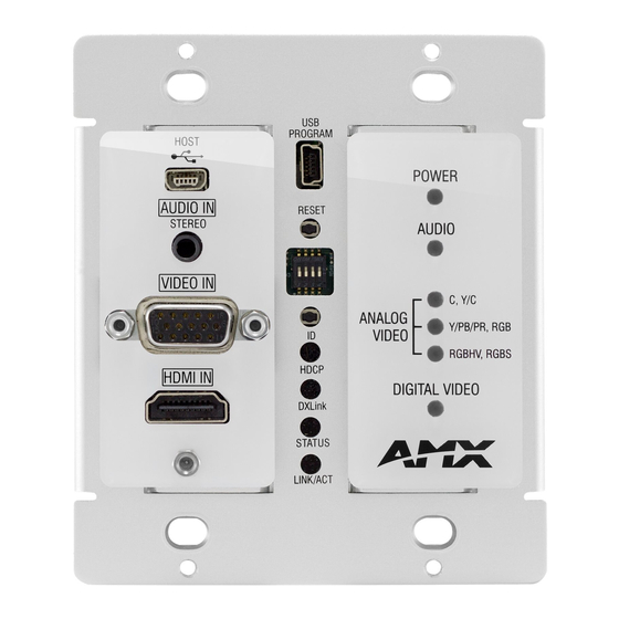
- Page 16 Product Overview and Specifications DXLink Multi-Format Wallplate TX (AVB-WP-TX-MULTI-DXLINK) Front View HDMI Input Left edge Digital Video LED Reset button HD-15 Input Program port Analog Video LEDs ID Pushbutton Audio LED Stereo Audio Input USB Host Power LED Bottom edge...
- Page 17 Product Overview and Specifications DXLink Decor Wallplate TX (AVB-DWP-TX-MULTI-DXLINK) Front View Reset button Program port Power LED Audio LED USB Host DIP switch Stereo Audio Input Analog Video LEDs HD-15 Input HDMI Input ID Pushbutton Digital Video LED Back box screw hole DXLink LEDs Cover plate screw hole NetLinx LEDs...
- Page 18 Power (from switcher) is applied to the unit LEDs (bottom edge of Wallplate TX) NetLinx - L (Link) Green Active LAN connection to an AMX Network (Blinking = #3 Toggle OFF) NetLinx - S (Status) Green • Speed status is 100 Mbps •...
- Page 19 Product Overview and Specifications HDMI TX Rear View (product discontinued) USB port HDMI In connector Stereo Audio In jack Digital Audio In jack Power jack Ground screw ICS LAN 10/100 connector IR ports RS-232 port DXLink output connector FIG. 6 HDMI TX rear view Note: The Multi-Format TX and HDMI TX each have a DIP switch on the bottom (see page 25).
- Page 20 Product Overview and Specifications ICS LAN10/100 Connector The ICS LAN 10/100 (RJ-45) connector provides for Ethernet 10/100 connectivity (e.g., receiving SEND_COMMANDs and downloading firmware update files). For pinout and LED information, see page 50. RS-232 (Serial) Port The RS-232 port (serial data interface) is a 3-position screw terminal block which accepts data from the source device and transfers it via the twisted pair cable to the HDMI RX, which in turn transfers the data to the destination device.
- Page 21 Product Overview and Specifications Wallplate TX and Decor Wallplate TX Rear View Located on the rear of the Wallplate TX are a DXLink (RJ-45) connector and a DIP switch. The Decor Wallplate TX also has its DXLink connector on the rear, but its DIP switch is on the front (see page 25).
-
Page 22: Receiver
Product Overview and Specifications Receiver Note: If a DVI-D signal is used (via a DVI-to-HDMI cable adapter), the advanced audio support from HDMI will not be available. DXLink HDMI Receiver (AVB-RX-HDMI-DXLINK) Front View IR LEDs NetLinx LEDs USB LED Video and Audio LEDs Power LED Scaling LEDs Program port... -
Page 23: Receiver Rear View
Serial TX active communication Serial RX Yellow Serial RX active communication NetLinx Link/Act Green Active LAN connection to an AMX Network (Blinking = #3 Toggle OFF) NetLinx Status Green LAN connection is active CEC is not currently supported Yellow USB port connection is established (for details, see page 27) * When the output cable is disconnected from the HDMI RX or if no EDID can be found on the destination device, the last used Scaling Mode LED will be ON. - Page 24 Product Overview and Specifications Ground Screw The ground screw is for creating a technical ground for the ungrounded sources/destinations with respect to the DXLink Transmitters/Receivers and switcher (see page 47). DXLink Input Connector The DXLink (RJ-45) connectors transport digital video, embedded audio, Ethernet, and bidirectional control over twisted pair cable to DXLink devices or boards, including digitally transcoded analog video signals.
-
Page 25: Common Features/Functionality
Product Overview and Specifications Common Features/Functionality This section covers the DIP switches, the USB port, HDCP compliance, and IR functionality. DIP Switches Tip: For easiest access to the DIP switch toggles, we recommend setting them before installation. A four-toggle DIP switch is on the bottom of the DXLink Modules, on the rear of the Wallplate TX, and on the front of the Decor Wallplate TX (the front can be covered with a customer provided standard decor style front cover plate). - Page 26 Product Overview and Specifications USB Port (Rear) DXLink Multi-Format TX USB port - host USB port - keyboard/mouse DXLink HDMI RX FIG. 12 TX USB port = host (top); RX USB port = keyboard/mouse (bottom) Multi-Format and HDMI Transmitters The USB-B port on the rear of the Multi-Format TX and HDMI TX can be connected to a PC to support a USB device.
- Page 27 HID Devices A list is available of HID devices which have been tested and found to be working well with the latest firmware (see “DXLink - HID supported Devices” on the DXLink Receiver’s product page at http://www.amx.com/ products/AVB-RX-DXLINK-HDMI.asp). USB LED info USB LED The USB LED on the front of a Transmitter or Receiver Module monitors the USB port on the rear of the unit.
-
Page 28: Quick Reference Tables For Modes
Product Overview and Specifications Quick Reference Tables for Modes The modes listed in the following three tables are those supported by DXLink Transmitters and Receivers. The Quick Reference Tables are intended to help users navigate the many modes available for system setup and use. For complete information on any of the modes listed, see the relevant sections or chapter referenced at the end of the Descriptions. - Page 29 Product Overview and Specifications Quick Reference Table – Modes for Handling Addressing/Networking (continued) Master Connection Master Connection Modes refer to the modes of communication used for connection to the Modes Master as specified via the SET CONNECTION Telnet command. Auto Mode: •...
-
Page 30: Dxlink Transmitters And Receiver Specifications
Thermal Dissipation, Multi-Format TX 34 BTU/hr. (13.5 V), HDMI TX 31 BTU/hr., Local 12 V Supplied (max.) HDMI RX 61 BTU/hr. AMX reserves the right to modify its products and their specifications without notice. Instruction Manual – DXLink™ Twisted Pair Transmitters/Receiver... - Page 31 ** “Common building” is defined as: Where the walls of the structure(s) are physically connected and the structure(s) share a single ground reference. AMX reserves the right to modify its products and their specifications without notice. Instruction Manual – DXLink™ Twisted Pair Transmitters/Receiver...
- Page 32 Compatibility Note: DXLink Transmitters and Receivers are compatible with other DXLink products (see the Compatible AMX Products listed in the table above). The Wallplate TX and the Decor Wallplate TX require an approved DXLink power injector (see table above) when connecting directly to an HDMI RX (Transmitters require firmware v1.2.40 or later;...
- Page 33 Note: Interlaced and progressive video are supported into the Transmitter; progressive is only supported out of the Receiver unless in non-scaling Bypass mode. AMX reserves the right to modify its products and their specifications without notice. Instruction Manual – DXLink™ Twisted Pair Transmitters/Receiver...
- Page 34 * Interlaced video is supported into the Transmitters; progressive is only supported out of the Receiver unless it is in Scaler Bypass mode. AMX reserves the right to modify its products and their specifications without notice. Instruction Manual – DXLink™ Twisted Pair Transmitters/Receiver...
- Page 35 3.5 mm mini-stereo jack (analog stereo) * S/PDIF specifications do not apply to the Wallplate TX or to the Decor Wallplate TX. AMX reserves the right to modify its products and their specifications without notice. Instruction Manual – DXLink™ Twisted Pair Transmitters/Receiver...
-
Page 36: Installation And Setup
Installation and Setup Installation and Setup Site Recommendations When placing the DXLink Transmitters and Receivers in an installation, follow the recommendations and precautions in this section to reduce potential setup and operation hazards. Environment Choose a clean, dust free, (preferably) air-conditioned location. ... -
Page 37: Setup Information
Collect all documentation. Note: Please save the original shipping container and packing materials. AMX is not responsible for damage caused by insufficient packing during return shipment to the factory. Shipping boxes are available; for details, contact your AMX representative. - Page 38 see the switcher’s Instruction Manual for information on the EDID programming functionality in DGX Configuration Software (available at www.amx.com). SEND_COMMANDs can also be used (see page 78). If Receivers are part of an Enova DGX endpoint system which requires scaler control and settings, see the ...
- Page 39 Installation and Setup Options for System Setup with Enova DGX DXLink Boards The following table contains options for using DXLink Transmitters and Receivers in conjunction with DXLink Twisted Pair Input and Output Boards in an Enova DGX Digital Media Switcher. System Setup Options –...
- Page 40 Installation and Setup Functions of DXLink Transmitters and Receivers The diagram in FIG. 14 shows the functions of DXLink Transmitters and Receivers. The example descriptions contain the device HDCP key count when used in conjunction with DXLink Boards in an Enova DGX Digital Media Switcher and when using a Transmitter and Receiver as a standalone pair.
- Page 41 Installation and Setup Extender Mode (Standalone): Example of Typical System Setup A Transmitter and Receiver standalone pair can also work together as an extender solution for transmission of HDMI over twisted pair cable up to 328 feet (100 m). The standalone setup supports DVI-D signals with the use of a DVI-to-HDMI cable adapter.
- Page 42 For additional information on power supplies and power supply troubleshooting for an Enova DGX Switcher, see the Instruction Manual – Enova DGX 8/16/32 Digital Media Switchers at www.amx.com. For power supply replacement information, contact technical support (see page 102).
- Page 43 Installation and Setup Avoiding Network (Ethernet) Loops Caution: Be careful not to create a network (Ethernet) loop. Only one connection to a LAN is permitted within a switching system with DXLink support. Network loops must be avoided (see FIG. 17). Example In the example in FIG.
- Page 44 Installation and Setup Setting DIP Switch #1 to Enable/Disable Access to ICS LAN 10/100 Port The #1 Toggle is used for enabling/disabling network activity over the physical ICS LAN 10/100 port. It does not affect network activity over DXLink. (For SEND_COMMANDs to disable/enable ICS LAN functionality, see page 96.) Note: #1 Toggle settings do not apply to Wallplate TX &...
- Page 45 Ethernet pass through to networked device* * Connect the ICS LAN 10/100 port of the DXLink unit to the network device (e.g., laptop, IP controlled projector, AMX ICSLan EXB Device). In a standalone setup, connect the ICS LAN 10/100 port of the other DXLink unit to the network.
- Page 46 The Multi-Format TX, HDMI TX, and HDMI RX are classified as V Style modules, which have optional V Style mounting hardware. These versatile mounting options include rack trays and mounting brackets for desktops, under desks, on walls, and on poles. For details on V Style Mounting Kit options, see www.amx.com. V Style Single Module Pole Mount...
- Page 47 Installation and Setup Attaching a Ground Wire to DXLink Transmitters/Receivers Note: Technically this type of grounding is only required when a DXLink Transmitter or Receiver is connected to an ungrounded device, but this added grounding measure can be used at the discretion of the installer. If the system is experiencing problems with delivery of DXLink signals to/from an Enova DGX Digital Media Switcher or Enova DVX Solution, adding a ground wire from the TX/RX to the switcher may improve performance.
- Page 48 Installation and Setup Ensure the ground wire is positioned so that it does not interfere with any of the connectors. Correctly positioned ground wires FIG. 23 Position ground wire away from connectors Attach the ground wire to a common earthed ground (see “Attaching a Ground Wire to a Common Earthed Ground” on the previous page).
- Page 49 For more details and helpful cabling information, reference the white paper titled “Cabling for Success with DXLink” available at www.amx.com or contact your AMX representative. * “Common building” is defined as: Where the walls of the structure(s) are physically connected and the structure(s) share a single ground reference.
- Page 50 Installation and Setup Twisted Pair Cable Pinouts The pinout in FIG. 26 is for twisted pair cable that connects to the ICS LAN 10/100 connector or to the DXLink connector on the Transmitters and Receivers. Use either the T568A or T568B pinout specification for termination of the twisted pair cable used between the modules in a standalone setup or between Transmitters and Receivers and an enclosure in a full system.
- Page 51 Installation and Setup NetLinx Connector LEDs (Wallplate TX/Decor Wallplate TX only) The following information applies to the NetLinx LEDs on the bottom edge of the Wallplate TX and on the front of the Decor Wallplate TX, which reflect NetLinx communication and status via their DXLink lines (FIG. 28). Front of Decor Wallplate TX On bottom edge of Wallplate TX S - Green...
- Page 52 Installation and Setup Audio Type Precedence The connectors for bringing audio into the system on the Transmitters are as follows: HDMI In connector – Embedded audio signal Digital Audio In jack – Digital audio signal (S/PDIF); not available on the Wallplate TX and ...
-
Page 53: Wallplate Transmitters - Attaching Signal/Transport Cables
Installation and Setup Wallplate Transmitters – Attaching Signal/Transport Cables Important: If network connection is required – before attaching cables, set DIP switch #3 Toggle. Important: Do not use the RJ-45 connector on rear for connecting to a standard Ethernet Network. To attach signal and transport cables to a Wallplate TX or Decor Wallplate TX: Install double-gang back box. - Page 54 Power (from switcher or DXLink power injector) is applied LEDs (bottom edge of Wallplate TX) NetLinx - L (Link) Green Active LAN connection to an AMX Network (Blinking = #3 Toggle OFF) NetLinx - S (Status) Green • Speed status is 100 Mbps •...
-
Page 55: Multi-Format Tx Or Hdmi Tx - Attaching Signal, Transport, And Control Cables
Installation and Setup Multi-Format TX or HDMI TX – Attaching Signal, Transport, and Control Cables Important: Before attaching cables, be sure to set the DIP switch’s toggles if necessary (see page 44). Important: Do not use the RJ-45 connector labeled “DXLink” for connecting to a standard Ethernet Network. Note: Power, IR, and RS-232 ports are covered in their own sections. -
Page 56: Multi-Format Tx Or Hdmi Tx - Applying Power
Remote power can only be provided via a switcher or a DXLink power injector. AMX does not support the use of any other power supplies or power injectors as these may potentially damage the DXLink equipment. -
Page 57: Hdmi Rx - Attaching Signal And Control Cables
Installation and Setup Multi-Format TX and HDMI TX– LED Troubleshooting If indicator LEDs for modules do not respond with a normal display as stated in table on previous page: Check all power connections. Check the “Detailed NetLinx (Link/Act and Status) LED Behavior” section on page 62. ... -
Page 58: Hdmi Rx - Applying Power
Serial TX Serial TX active communication Serial RX Yellow Serial RX active communication NetLinx Link/Act Green Active LAN connection to an AMX Network (Blinking = #3 Toggle OFF) NetLinx Status Green LAN connection is active CEC is not currently supported Yellow... -
Page 59: Serial Data Transfer And Ir Flow Control
Endpoint Mode with an Enova Digital Media Switcher. The switcher has an integrated NetLinx Central Control Processor which provides native AMX control at each remote location fed by a DXLink Transmitter or Receiver. Control is sent over twisted pair cable (via the DXLink ports). This also holds true when Enova DVX Solutions are used. -
Page 60: Optional: Multi-Format Tx, Hdmi Tx, And Hdmi Rx - Ir Control
Installation and Setup Optional: Multi-Format TX, HDMI TX, and HDMI RX – IR Control For additional information on the IR03 and CC-NIRC, which are required for IR control, see page 27. (The IR03 and CC-NIRC are not included with the modules.) A compatible remote control unit can also be used with the system. In addition to being directly connected to a device, this port can be connected as an independent native NetLinx control port from a networked NetLinx Central Controller. -
Page 61: Id Pushbutton Functions
Bypass Mode – allows the video signal to display over the destination device without altering the signal’s resolution. Auto Mode (default) – allows the destination device to choose the resolution it needs (this mode is AMX’s ® SmartScale Technology in action). -
Page 62: Detailed Netlinx (Link/Act And Status) Led Behavior
Installation and Setup Note: The scaling mode (and the aspect ratio) can also be set on the DXLink Output Board using DGX Configuration Software. The data is persisted on the board and sent to the HDMI RX. Persistence of Scaling Options The HDMI RX defaults to “Auto”... -
Page 63: Dxlink Tx/Rx In A Multiple-Stage Switching System
DXLink line are the video and audio signals. When connecting switching systems via DXLink ports, AMX recommends no more than three switcher throughputs (see the “Example” below). -
Page 64: Network Configuration
Network Configuration Network Configuration Overview DXLink Modules support two IP Addressing Modes: Static IP and DHCP (with link-local fallback*). To avoid having a large system consume numerous IP addresses, the Transmitter and Receiver default to disabling the network connection functionality. Therefore, the #3 Toggle must be set to ON before the Transmitter or Receiver can establish a network connection (see page 45). -
Page 65: Telnet Ip Configuration Commands
NDP (NetLinx Discovery Protocol) capabilities as well as IP discovery via NetLinx Studio. Note: NDP is a device discovery method used by NetLinx Masters. With NDP Beacon enabled, the Master will transmit NDP Beacons for AMX’s proprietary device discovery. Telnet IP Configuration Commands The SET IP and GET IP Telnet commands listed in the tables in Appendix B (which start on page 109) can be sent directly to the device via a Telnet terminal session. -
Page 66: Factory Default Parameters
DNS1 (for static mode) 192.168.1.1 DNS2 (for static mode) 192.168.1.1 DNS3 (for static mode) 192.168.1.1 DNS Domain amx.com Hostname Last 7 digits of the serial number Master Connection Mode NDP - For details, see page 116. Master URL “” (blank) -
Page 67: Device Ids
Network Configuration Device IDs Device IDs Model ID (16-bits) Bound ID (16-bits) Unbound HDMI-TX Module (AVB-TX-HDMI-DXLINK) 0x017C 0x014B Multi-Format TX Module (AVB-TX-MULTI-DXLINK) 0x017F 0x014B Multi-Format Wallplate TX (AVB-WP-TX-MULTI-DXLINK) 0x017E 0x014B Decor Wallplate TX (AVB-DWP-TX-MULTI-DXLINK) 0x018B ______ HDMI-RX Module (AVB-RX-DXLINK-HDMI) 0x017D 0x014B Using the ID Pushbutton The ID Pushbutton is located on the right front of the modules, on the left edge of the Wallplate TX, and on the front of... - Page 68 The device must first be placed in ID Mode in NetLinx Studio or the momentary press will be ignored. Note: The latest version of NetLinx Studio is available to download and install from www.amx.com. Refer to the NetLinx Studio online help for instructions on using the application.
- Page 69 Network Configuration Reset the Factory Default Settings During power up – if the ID Pushbutton is held until the Control/NetLinx LEDs toggle back and forth in unison approximately 10 times, then released when the faster blinking starts, the Transmitter or Receiver will reset to its factory default settings, which affect the parameters but not the firmware version.
- Page 70 Network Configuration Restore the Factory Firmware Image and Factory Default Parameters During power up – if the ID Pushbutton is held until the Control/NetLinx LEDs toggle back and forth in unison approximately 30 times (10 slow, 20 fast) and then released when they go solid, the module’s factory firmware image will be restored.
- Page 71 Network Configuration Once all actions in Step 3 are completed, the LEDs all turn off, indicating the unit is ready to reboot. The unit automatically reboots to complete the process. Tip: To monitor the ID Pushbutton boot state of a module, see the “ID Pushbutton Boot and NetLinx LED Behavior”...
-
Page 72: Irl File Transfers
IRL File Transfers IRL File Transfers Overview The NetLinx Studio software application (available for free download from www.amx.com) provides the ability to transfer IR Library files to NetLinx devices such as DXLink Transmitters and Receivers. Endpoint System (with a Switcher) When a Transmitter and/or a Receiver are being used in conjunction with a switcher as an endpoint system, the switcher’s integrated Master is used for the IRL file transfer. -
Page 73: Preparing For Irl File Transfers In An Endpoint System
Go to www.amx.com and login as a Dealer to download the latest version. Download the applicable IRL file from www.amx.com (Partners / Search Devices) to your PC. Verify the following: Verify that an Ethernet/RJ-45 cable is connected from the switcher’s integrated Master to the network (e.g., from the LAN 100/1000 port on an Enova DGX 32 to a LAN). -
Page 74: Preparing For Irl File Transfers In An Extender System
Go to www.amx.com and login as a Dealer to download the latest version. Download the applicable IRL file from www.amx.com (Partners / Search Devices) to your PC. No Master on the network: Use your PC to set up a Virtual NetLinx Master (see page 118) in NetLinx Studio (leave NetLinx Studio open to the OnLine Tree when done). -
Page 75: Transferring Irl Files
IRL File Transfers Transferring IRL Files The File Transfer tool in NetLinx Studio is used to map IRL files to DXLink Transmitters and Receivers. The instructions below assume that the preparations on the previous pages for either an endpoint system or an extender system have been completed. - Page 76 IRL File Transfers Select the type of file (in this case, IRL/IRV Files) that you want to add to the File list for transfer. Click Add. A standard Open dialog box opens with the Files of type selection set to IR Code files (*.IRL/*.IRV). Locate and select the IRL file that you want to add.
- Page 77 Click Send to transfer the file to the Transmitter or Receiver that the file is mapped to. Additional Documentation For additional information on using NetLinx Studio, refer to the Instruction Manual – NetLinx Studio v3.3 and the WebConsole & Programming Guide – NetLinx Integrated Controllers (available at www.amx.com). Instruction Manual – DXLink™ Twisted Pair Transmitters/Receiver...
-
Page 78: Netlinx Programming Of Dxlink Transmitters And Receivers
NetLinx Programming of DXLink Transmitters and Receivers NetLinx Programming of DXLink Transmitters and Receivers Overview Important: Before DXLink TXs and RXs can receive any NetLinx SEND_COMMANDs, the DIP switch’s #3 Toggle must be set to ON or the devices will not be accessible from a NetLinx control system. The DXLink Transmitters and Receivers recognize a select number of SEND_COMMANDs and CHANNELs. - Page 79 NetLinx Studio OnLine Tree - Ports 1 through 7 on a DXLink HDMI Transmitter and Receiver Note: For additional information on NetLinx Studio, refer to the “Instruction Manual – NetLinx Studio v3.3” and the “WebConsole & Programming Guide – NetLinx Integrated Controllers” (available at www.amx.com). Note: All command text is based on a Unicode index.
-
Page 80: Channels
NetLinx Programming of DXLink Transmitters and Receivers CHANNELs Channel Function This channel On indicates that the DXLink Module has a valid UTP (twisted pair cable) connection to a switcher with an integrated Master. If the channel is Off, the DXLink Module is incorrectly connected. 1-253 Key presses from selected remote control. - Page 81 NetLinx Programming of DXLink Transmitters and Receivers Video SEND_COMMANDs (Receivers), continued ?VIDOUT_RES Syntax: Requests the resolution and SEND_COMMAND <DEV>,"'?VIDOUT_RES'" Variables: refresh rate of the video through the Receiver. • horizontal = An integer value representing the horizontal. Note: If the Scaling Mode is •...
-
Page 82: Dxlink Receiver Audio Send_Commands
NetLinx Programming of DXLink Transmitters and Receivers Aspect Ratio Options Stretch (to fit) – This option (default) scales the video to full screen size in both horizontal and vertical directions regardless of the input aspect ratio. No data is cropped. However, the image may be distorted as needed to fill the screen. When Stretch is selected, black bars are not added by the scaler. -
Page 83: Dxlink Transmitter Video Send_Commands
NetLinx Programming of DXLink Transmitters and Receivers DXLink Transmitter Video SEND_COMMANDs DXLink Transmitter Video SEND_COMMANDs are sent to Port 7 unless otherwise noted. Note: Asynchronous notifications are available for the Transmitters via NetLinx Studio (and Telnet). Note: All text is based on a Unicode index. Video SEND_COMMANDs (Transmitters) Command Description... - Page 84 NetLinx Programming of DXLink Transmitters and Receivers Video SEND_COMMANDs (Transmitters), continued ?VIDIN_STATUS Important: Send to Port 7 for digital video or to Port 8 for analog video. Syntax: Requests the status of the video input on the Transmitter. SEND_COMMAND <DEV>,"'?VIDIN_STATUS'" Variable: Important: In the case of the Multi-Format TX, Wallplate TX,...
- Page 85 NetLinx Programming of DXLink Transmitters and Receivers Video SEND_COMMANDs (Transmitters), continued Video SEND_COMMANDs (Transmitters), continued VIDIN_RES_REF Important: Send to Port 7 or Port 8. Syntax: Sets the resolution and refresh rate of the video SEND_COMMAND <DEV>,"'VIDIN_RES_REF- <horizontal>x<vertical>,<rate>'" Variables: through the Transmitter (disable VIDIN_RES_AUTO •...
- Page 86 NetLinx Programming of DXLink Transmitters and Receivers Video SEND_COMMANDs (Transmitters), continued VIDIN_HDCP Important: Send to Port 7. Note: When VIDIN_HDCP is disabled, the addressed video input will appear to any Sets the video input HDCP source as not being HDCP compliant. For PC sources that encrypt all video when compliance setting of the connected to an HDCP compliant display, disabling HDCP compliance on the input will video input port addressed by...
-
Page 87: Dxlink Transmitter Audio Send_Commands
NetLinx Programming of DXLink Transmitters and Receivers Video SEND_COMMANDs (Transmitters), continued ?VIDIN_PHASE Important: Send to Port 8. This command is valid only for inputs whose format is set to VGA. Requests the input phase of the RGB video input port Syntax: addressed by the D:P:S. -
Page 88: Ir Send_Commands
NetLinx Programming of DXLink Transmitters and Receivers IR SEND_COMMANDs On the DXLink Transmitters and Receiver Modules, IR CHANNELS and SEND_COMMANDs are sent to Port 3 (IR output). IR CHANNELs Channel Function 1-255 Generate the IR or serial command assigned to that channel. IR SEND_COMMANDs IR SEND_COMMANDs (Transmitters and Receivers) Command... - Page 89 NetLinx Programming of DXLink Transmitters and Receivers IR SEND_COMMANDs (Transmitters and Receivers), continued Command Description CTOF This command sets the delay time between pulses generated by the 'CH' or 'XCH' Send Commands in tenths of seconds. Set the duration of the Off Syntax: time (no signal) between IR pulses for channel and IR...
- Page 90 NetLinx Programming of DXLink Transmitters and Receivers IR SEND_COMMANDs (Transmitters and Receivers), continued SET MODE (IR command) SET MODE Syntax: Set an IR port to either IR, SEND_COMMAND <DEV>,"'SET MODE'<mode>" Variable: Serial, or Data mode. mode = • IR (standard IR output with carrier) •...
- Page 91 NetLinx Programming of DXLink Transmitters and Receivers IR SEND_COMMANDs (Transmitters and Receivers), continued XCHM Syntax: Changes the IR output SEND_COMMAND <DEV>,"'XCHM <extended channel mode>'" Variable: pattern for the 'XCH' Send Command. extended channel mode = 0 to 4. Example: SEND_COMMAND IR_1,"'XCHM 3'" Sets the IR device’s extended channel command to mode 3.
-
Page 92: Serial Send_Commands
NetLinx Programming of DXLink Transmitters and Receivers Serial SEND_COMMANDs On the DXLink Modules, SERIAL SEND_COMMANDs are sent to Port 1. Serial SEND_COMMANDs (Transmitters and Receivers) Command Description B9MOFF This command works in conjunction with the 'B9MON' command. • Disables 9-bit in 232 mode. Set the port’s communication parameters for stop and data •... - Page 93 NetLinx Programming of DXLink Transmitters and Receivers Serial SEND_COMMANDs (Transmitters and Receivers), continued RXCLR Syntax: Clear all characters in the SEND_COMMAND <DEV>,"'RXCLR'" Example: receive buffer waiting to be sent to the Master. SEND_COMMAND dvRXRS232,"'RXCLR'" Clears all characters in the receive buffer waiting to be sent to the Master. RXOFF Syntax: Disable the transmission of...
-
Page 94: Dxlink Transmitter Usb Send_Commands
NetLinx Programming of DXLink Transmitters and Receivers DXLink Transmitter USB SEND_COMMANDs On the DXLink Transmitter, USB SEND_COMMANDs are sent to Port 5. USB SEND-COMMANDs (Transmitter) Command Description ?USB_HID_SERVICE Syntax: Requests the status for SEND_COMMAND <DEV>,"'?USB_HID_SERVICE'" the USB HID pass Example: through setting (Enable or SEND_COMMAND dvTX,"'?USB_HID_SERVICE'"... -
Page 95: Common Dxlink Transmitter / Receiver Send_Commands
NetLinx Programming of DXLink Transmitters and Receivers Common DXLink Transmitter / Receiver SEND_COMMANDs Common NetLinx SEND_COMMANDs for the DXLink Transmitters and Receivers are provided in the following table. These commands can be sent to any port (the #3 Toggle must be set to ON). Common NetLinx SEND-COMMANDs (Transmitters and Receivers) Command Description... -
Page 96: Dxlink System Send_Commands
NetLinx Programming of DXLink Transmitters and Receivers DXLink System SEND_COMMANDs DXLink System SEND_COMMANDs can be sent to any port on the Transmitters or Receiver. DXLink System SEND_COMMANDs (Transmitters and Receivers) Command Description ?DXLINK Syntax: SEND_COMMAND <DEV>,"'?DXLINK'" Requests the current mode for the TX Example: or RX. -
Page 97: Send_String Escape Sequences
NetLinx Programming of DXLink Transmitters and Receivers SEND_STRING Escape Sequences The DXLink Modules support several special SEND_STRING escape sequences. If any of the character combinations listed below are found anywhere within a SEND_STRING program instruction, they will be treated as a command and not the literal characters. -
Page 98: Enova Dvx Switchers - Dxlink Send_Commands
Additional SEND_COMMANDs for Enova DVX Switchers can be found in the specific product manual at www.amx.com. Important: The #3 Toggle on the Transmitter or Receiver must be set to ON before the commands in the table below are sent to the switcher. -
Page 99: Troubleshooting
Troubleshooting Troubleshooting Overview The troubleshooting suggestions/strategies provided apply to the Transmitters and the Receiver, unless otherwise noted. Five potential types of issues are covered in this chapter: Basic troubleshooting Determining HDCP compliance Power DXLink connections Network setup ... -
Page 100: Power Issues
Troubleshooting Power Issues Upon power up, the Power indicator LED on the front of the DXLink units illuminates solid green. If the Power LEDs on any of the system’s equipment are not illuminated: Check the power cords or DXLink (RJ-45) connection if using power over the DXLink line. ... -
Page 101: Dxlink Connection Issues
Troubleshooting DXLink Connection Issues One method for determining DXLink connection issues is to compare the pattern of the green and yellow DXLink LEDs on the Transmitter or Receiver against the tables below and then check the suggested items in the Troubleshooting column in the second table. -
Page 102: Network Setup Issues
If this manual has not satisfactorily answered your questions regarding the DXLink Transmitters and Receivers or they are not operating as expected, please contact your AMX representative or technical support. Have the serial numbers for the modules ready. If the modules are connected to a switcher, locate the serial number for the switcher too.* We recommend recording the serial numbers in an easily accessible location. -
Page 103: Appendix A - Upgrading The Firmware
Appendix A – Upgrading the Firmware Overview The NetLinx Studio software application (available for free download from www.amx.com) provides the ability to transfer KIT files to NetLinx devices such as DXLink Transmitters and Receivers. The firmware on the Transmitters and Receiver can be upgraded in the field. -
Page 104: Preparing For Kit File Transfers In An Endpoint System
Go to www.amx.com and login as a Dealer to download the latest version. Download the latest Firmware (KIT) file from www.amx.com on the Transmitter or Receiver product page to your PC. (Place KIT files on a local drive for speedy throughput.) -
Page 105: Important Upgrade Information
Appendix A – Upgrading the Firmware Master on the network: Launch NetLinx Studio and open the OnLine Tree. Apply power to module and set it to DHCP Mode.* On the bottom of module, set the DIP switch’s #1 and #3 Toggles to ON. (Remember to set the #1 and #3 Toggles back to OFF when the file transfer is complete if the module does not require network connectivity.) Connect an RJ-45 cable from the ICS LAN 10/100 port on the Transmitter or Receiver Module to the PC running NetLinx Studio. - Page 106 Appendix A – Upgrading the Firmware Firmware Versions The following table contains firmware version information for the DXLink units. DXLink Firmware Versions Applies to Version # Date Differences HDMI RX 1.0.80 10/19/2012 • A/V SEND_COMMANDs respond with STRINGs and earlier •...
-
Page 107: Transferring Kit Files
Appendix A – Upgrading the Firmware Transferring KIT Files The system will be non-operational during the upgrade procedure. The Firmware Transfers tool in NetLinx Studio is used to map KIT files to DXLink Transmitters and Receivers. The instructions below assume that the preparations on the previous pages for an endpoint system have been completed. To send a KIT file to a Transmitter or Receiver: In NetLinx Studio from the Tools menu, select “Firmware Transfers >... -
Page 108: Appendix B - Telnet (Terminal) Commands
Welcome Banner with and without Security Enabled: Without Telnet security enabled, a session will begin with a welcome banner similar to the following: Welcome to DXLINK-HDMI-RX 0.0.106.0 Copyright AMX LLC 2011 > If Telnet security is enabled, user credentials are required: ... -
Page 109: Telnet Username And Password
Appendix B – Telnet (Terminal) Commands To establish a terminal connection via NetLinx Studio: 1. In the Online Tree, select the DXLink unit and right-click to access the short-cut menu. Select Launch Telnet Window via NetLinx Studio. The Telnet window opens and the welcome banner appears. 3. -
Page 110: Telnet Commands
Note: Devices other than the DXLink Transmitter or Receiver itself will be ignored. Example: >device status 32002:1:0 Device Status ------------- Device 32002 AMX LLC,DXLINK-HDMI-RX, 0.0.106.0 contains 7 Ports Port 1 - Channels:255 Levels:8 MaxStringLen=64 Types=8 bit MaxCommandLen=64 Types=8 bit The following input channels are on:None... - Page 111 Lease Renew (T1): SAT 01/11/2031 00:59:02 (129600 sec) Lease Rebind (T2): SUN 01/12/2031 03:59:02 (226800 sec DNS Servers -------------------------------- Domain suffix: amx.internal Entry 1: 192.168.40.7 Entry 2: 192.168.40.8 Note: The system number and IP addressing information displayed is reflective of actual operating values, not stored parameters.
- Page 112 Gets the list of DNS entries. Example: >get dns DNS Servers ------------------------------- Domain suffix: amx.internal Entry 1: 192.168.40.7 Entry 2: 192.168.40.8 Note: When the DXLink Transmitter or Receiver is in DHCP Mode, these are active values, NOT the stored values that only apply to Static IP Mode.
- Page 113 Enter DNS Entry 2 : 12.18.110.8 Enter DNS Entry 3 : 12.18.110.7 You have entered: Domain Name: amx.com DNS Entry 1: 192.168.20.5 DNS Entry 2: 12.18.110.8 DNS Entry 3: 12.18.110.7 Is this correct? Type Y or N and Enter -> Y Settings written.
- Page 114 • Maximum length = 25 characters. If the name entered exceeds 25 characters, it will be truncated. • The value is stored in non-volatile memory. • If no value specified, an automatic name consisting of AMX, the product name, and serial number will be used. Note: This command requires a reboot to enable new settings.
- Page 115 Appendix B – Telnet (Terminal) Commands Telnet Commands (continued) SET TELNET PORT Sets the device’s IP port listened to for Telnet connections. Example: >SET TELNET PORT Current telnet port number = 23 Enter new telnet port number (Usually 23)(0 = disable Telnet): Once you enter a value and press the Enter key, you get the following message: Setting telnet port number to 23 New telnet port number set, reboot the device for the change to take effect.
-
Page 116: Master Connection Modes
UDP – Protocol does not have a built-in retry mechanism, but consumes fewer resources on the Master. AMX’s UDP implementation of NetLinx employs a retry mechanism to provide the reliability of TCP with the resource efficiency of UDP. URL vs. NDP vs. Auto Determining which connection method to use for Master Connection Mode is essentially a matter of deciding what information the device should use to identify the correct Master to connect to. -
Page 117: Notes On Specific Telnet Clients
Appendix B – Telnet (Terminal) Commands Notes on Specific Telnet Clients Telnet and terminal clients exhibit different behaviors in some situations. This section states some of the known anomalies. Windows Client Programs ® Anomalies occur when using a Windows client if you are not typing standard ASCII characters (i.e., using the keypad and the Alt key to enter decimal codes). -
Page 118: Appendix C - Virtual Netlinx Master
Appendix C – Virtual NetLinx Master Appendix C – Virtual NetLinx Master Overview Virtual NetLinx Master (Masterless) A Virtual NetLinx Master can be created using your PC, which allows NetLinx Studio to facilitate direct file transfers to a DXLink Transmitter or Receiver when a Master is not available. Four basic procedures must be completed for Virtual Master file transfers: Set the PC to a static IP address (see below). - Page 119 Appendix C – Virtual NetLinx Master Note: The following procedure uses the most current version of Windows available at the time of publication. To set a PC to Static IP Mode: From the Start menu on the desktop taskbar, select Control Panel / Network Sharing Center. Click “Change adapter settings”...
-
Page 120: Creating A Virtual Master
Appendix C – Virtual NetLinx Master Creating a Virtual Master To create a Virtual Master in NetLinx Studio: Open NetLinx Studio. From the Settings menu, select Master Communication Settings. Click to open the Communication Settings dialog box Click Communication Settings on the right. The Communication Settings dialog box opens. -
Page 121: Preparing A Dxlink Unit To Work With A Virtual Master
Appendix C – Virtual NetLinx Master Under Virtual NetLinx Master Options: Optional – Change the Master System Number (default = 1; range = 1 to 65535). Select the desired IP Address in the Available Connections list (this will be the static IP address that the PC was set to in the previous instructions). - Page 122 Appendix C – Virtual NetLinx Master To assign a device ID and set the connection type: 1. From the Tools menu in NetLinx Studio, select Telnet Session. The Telnet Settings dialog box opens. Click the New button. The New Telnet Address dialog box opens. Enter the default static IP address for the DXLink unit: 192.168.1.2 and click OK.
-
Page 123: Appendix D - Cable Details And Pinout Info
Important: System configurations will vary, necessitating different cable requirements for each system. Cables not available through AMX should come from a trusted cable supplier. Note: When cabling video through either the HDMI port or HD-15 port, installers should be aware of how cabling will affect audio signals. -
Page 124: Hd-15 Connector Cable Pinout
Appendix D – Cable Details and Pinout Info HD-15 Connector Cable Pinout HD-15 connectors are found on the Multi-Format TX, Wallplate TX, and Decor Wallplate TX. These connectors are used to accept a variety of analog video signals from a source device. The following table provides cable pinout details for HD-15 connections for VGA, component, S-Video, and composite. -
Page 125: Dvi Pinout For Dvi-To-Hdmi Cable Adapter
Appendix D – Cable Details and Pinout Info DVI Pinout for DVI-to-HDMI Cable Adapter The pinout in FIG. 43 is for DVI-to-HDMI cable adapters which can be used with the modules when a DVI-I signal is required FIG. 43 DVI pinout for DVI-to-HDMI cable adapter DVI Connector Pinout DVI Input Pin # Signal Name... -
Page 126: Appendix E - Supported Input Resolutions
Appendix E – Supported Input Resolutions Appendix E – Supported Input Resolutions Available Pixel Display and Refresh Rate The available pixel display and refresh rates for the input devices connected to the DXLink Transmitters are listed in this appendix. The resolutions in the following tables are supported on the DXLink Transmitters and can be set using a SEND_COMMAND. - Page 127 Appendix E – Supported Input Resolutions DVI, HDMI, and VGA Supported Input Resolutions (continued) Resolution Horizontal Vertical Refresh HDMI and Comments Video Name Active Pixels Active Pixels (Hz) DVI Support Support Standard 1280x720@60 1280 VESA CVT 1280x720p@60 1280 720p...
- Page 128 Appendix E – Supported Input Resolutions Composite and S-Video Supported Input Resolutions Composite and S-Video Supported Input Resolutions Resolution Name Horizontal Vertical Refresh (Hz) Comments Video Standard Active Pixels Active Pixels 720x480i@60 480i 720x576i@50 576i Component Video Supported Input Resolutions Component Video Supported Input Resolutions Resolution Name Horizontal...
-
Page 129: Appendix F - Supported Output Resolutions
Appendix F – Supported Output Resolutions Appendix F – Supported Output Resolutions HDMI and DVI Supported Output Resolutions The resolutions in the following table are supported on the HDMI RX and can be set using a SEND_COMMAND. The horizontal/vertical/refresh information from the Resolution Name (in the first column) can be entered in a SEND_COMMAND command (VIDOUT_RES_REF) to specify scaling parameters for the HDMI RX. -
Page 130: Digital Video Output Resolution Support
Appendix F – Supported Output Resolutions Digital Video Output Resolution Support Important: The resolutions and timings in the lists in this section can only be set using DGX Configuration Software via the Enova DGX Switcher when the DXLink Receiver is being used directly from a DXLink output board. - Page 131 Appendix F – Supported Output Resolutions CVR (RGB Color Space): 768x480p@60Hz 800x600p@60Hz 800x600p@120Hz 848x480p@60Hz 960x600p@60Hz 1024x576p@60Hz 1024x640p@60Hz 1024x768p@60Hz 1024x768p@120Hz 1064x600p@60Hz 1152x720p@60Hz 1152x864p@60Hz 1224x768p@60Hz 1280x720p@60Hz 1280x768p@60Hz 1280x768p@120Hz 1280x800p@120Hz 1280x960p@60Hz 1280x1024p@60Hz 1360x768p@60Hz 1360x768p@120Hz 1400x1050p@60Hz 1440x900p@60Hz 1536x960p@60Hz 1600x1000p@60Hz 1600x1200p@60Hz 1680x1050p@60Hz 1704x960p@60Hz 1728x1080p@60Hz 1800x1350p@60Hz 1864x1050p@60Hz 1920x1080p@60Hz 1920x1200p@60Hz...
- Page 132 Appendix F – Supported Output Resolutions CVT (RGB Color Space): 640x360p@85Hz 1280x720p@50Hz 640x400p@75Hz 1280x720p@60Hz 640x400p@85Hz 1280x720p@75Hz 640x480p@75Hz 1280x720p@85Hz 640x480p@85Hz 1280x768p@50Hz 1280x768p@60Hz 768x480p@60Hz 1280x768p@75Hz 768x480p@75Hz 1280x768p@85Hz 768x480p@85Hz 1280x800p@50Hz 800x600p@50Hz 1280x800p@75Hz 800x600p@60Hz 1280x800p@85Hz 800x600p@75Hz 1280x960p@50Hz 800x600p@85Hz 1280x960p@60Hz 848x480p@50Hz 1280x960p@75Hz 848x480p@60Hz 1280x960p@85Hz 848x480p@75Hz 1280x1024p@50Hz 848x480p@85Hz 1280x1024p@60Hz...
- Page 133 Appendix F – Supported Output Resolutions DMR (RGB Color Space): 1280x800p@60Hz 1366x768p@60Hz 1600x900p@60Hz DMT (RGB Color Space): 640x350p@85Hz 640x400p@85Hz 640x480p@60Hz 640x480p@72Hz 640x480p@75Hz 640x480p@85Hz 720x400p@85Hz 800x600p@56Hz 800x600p@60Hz 800x600p@72Hz 800x600p@75Hz 800x600p@85Hz 848x480p@60Hz 1024x768i@43Hz 1024x768p@60Hz 1024x768p@70Hz 1024x768p@75Hz 1024x768p@85Hz 1152x864p@70Hz 1152x864p@75Hz 1152x864p@85Hz 1280x800p@60Hz 1280x960p@60Hz 1280x960p@75Hz 1280x960p@85Hz 1280x1024i@43Hz...
-
Page 134: Appendix G - Ground Wire Attachment
Appendix G – Ground Wire Attachment Appendix G – Ground Wire Attachment Applicability This appendix covers attaching a ground wire to a DXLink Module without a designated ground location. If the module has a designated ground screw, see page 47. If the system is experiencing problems with delivery of DXLink signals to/from an Enova DGX Digital Media Switcher or Enova DVX Solution, adding a ground wire from the TX/RX to the switcher may improve performance. - Page 135 Appendix G – Ground Wire Attachment Remove the jackscrew and silver washer above the HDMI connector. Remove jackscrew and washer FIG. 44 Remove jackscrew and washer above HDMI connector Secure the ring terminal of the ground wire against the chassis with the jackscrew and washer. Ensure the ground wire is positioned so that it does not interfere with any of the connectors.
-
Page 136: Appendix H - Edid Programming
EDID requirements for VGA. AMX’s DGX Configuration Software has a tabbed view for EDID Programming. This view can be used to re-program the EDID EEPROM chips for the HD-15 connectors on the DXLink Transmitters, allowing for custom configuration of the EDID data that is stored on them. -
Page 137: Dxlink Connection To Pc
Appendix H – EDID Programming DXLink Connection to PC To use DGX Configuration Software with a DXLink Transmitter: Attach one end of a USB mini-B cable to the Program port on the front of the Multi-Format Transmitter (on the Wallplate TX, the Program port is on the left side; on the Decor Wallplate TX, the Program port is in the center on the front under the customer provided cover plate). -
Page 138: Edid Programmer View
VGA EDID emulation file (by updating the EEPROM chip) which comes preloaded with an AMX VGA EDID set. The AMX VGA EDID set consists of a number of common EDID settings (for VGA timing details, see page 126). In most cases, the DXLink Transmitter can be used as is from the factory with no adjustments. -
Page 139: Edid Programmer View
Appendix H – EDID Programming Reading and Saving EDID Data from a DXLink TX’s HD-15 (VGA) Input Connector The DGX Configuration Software reads the EDID data from the USER EDID 1 EEPROM location, regardless of the VIDIN_EDID setting. Important: Unless a custom EDID has been previously written to the input, attempting to read the EDID will result in a Read Error message. - Page 140 The instructions that follow tell how to use the EDID Programmer view to write user defined VGA EDID information to the HD-15 input connector on a DXLink Transmitter. User defined VGA EDIDs are currently available from technical support. A library of VGA EDID files will be available on at www.amx.com in conjunction with a future firmware release.
- Page 141 - Schedules and registration for any AMX University course - Travel and hotel information - Your individual certification requirements and progress 3000 RESEARCH DRIVE, RICHARDSON, TX 75082 USA • 800.222.0193 • 469.624.8000 • 469-624-7153 fax • 800.932.6993 technical support • www.amx.com...
Need help?
Do you have a question about the DXLink Multi-Format Wallplate and is the answer not in the manual?
Questions and answers