
Related Manuals for AMX MX8


Summary of Contents for AMX MX8
- Page 1 MX Series MX8 and MX16 Relay Receivers M X W i r e l e s s S e r i e s...
-
Page 2: Limited Warranty And Disclaimer
Consumers should inquire from selling dealer as to the nature and extent of the dealer’s warranty, if any. AMX Corporation is not liable for any damages caused by its products or for the failure of its products to perform, including any lost profits, lost savings, incidental damages, or consequential damages. -
Page 3: Table Of Contents
IR operation..........................3 Configuration and Installation .................5 Selecting a Radio Code Group..................5 Setting the radio code group selection DIP switch on MX8 and MX16 relay receivers.... 6 Installation ......................... 7 Installing RF systems ....................... 7 Installing IR systems ........................ 7 Wiring IRX-SM+ or IRX-UM+ external IR receiver connectors .......... - Page 4 Table of Contents MX Series Relay Receiver Systems...
-
Page 5: Product Information
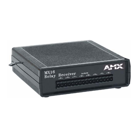
• IR (with external IR sensor): 418 MHz Relays • MX8 (IRX): 8 momentary contacts UL rated at: 1A @ 30 VDC / 0.5 A @ 120 VAC • MX16 (IRX): 8 momentary contacts UL rated at: 1A @ 30 VDC / 0.5 A @ 120 VAC... - Page 6 IR SENSOR OUTPUTS 12VDC Relay contacts 5-8 Relay contacts 1-4 External IR sensor connector 12 VDC power supply connector FIG. 1 Front Panel of the MX16 and Rear Panel of the MX8 (IRX) and MX16 (IRX) MX Series Relay Receiver Systems...
-
Page 7: Operation
IR operation Pointing an AMX wireless transmitter at an external IR sensor (IRX-UM+ or IRX-SM+) and pressing a button on the transmitter sends a signal to the receiver. The relay corresponding to the pressed button is activated, closing the contact and controlling the associated device. - Page 8 Product Information MX Series Relay Receiver Systems...
-
Page 9: Configuration And Installation
Radio code groups are necessary in order to allow two or more transmitters to operate in close proximity without interfering with each other. MX8 and MX16 radio code groups are set with the internal 4-position code selection DIP switch. The DIP switch is located on front of the circuit board inside the MX8 and MX16, as shown in FIG. -
Page 10: Setting The Radio Code Group Selection Dip Switch On Mx8 And Mx16 Relay Receivers
Setting the radio code group selection DIP switch on MX8 and MX16 relay receivers The code group of the MX8 or MX16 receiver must match the code group of the transmitter. FIG. 4 shows the MX8 and MX16 receiver 4-position radio code group DIP switch, and the ten-position TXC+ transmitter DIP switch. -
Page 11: Installation
Wiring IRX-SM+ or IRX-UM+ external IR receiver connectors Connect one or more optional IRX-SM+ swivel-mount IR receivers or IRX-UM+ IR UniMount IR receivers to the MX8 (IRX) or MX16 (IRX), as shown in FIG. 5. You can wire up to eight IR receivers in parallel. -
Page 12: Troubleshooting
Configuration and Installation Troubleshooting The following tables contain troubleshooting information for the TXC+, MX8 and MX16 receivers. TXC+ Transmitter Troubleshooting Information Problem Possible solution Red transmit LED does not light when • Check for installed batteries. a button is pressed. -
Page 13: Mx8/16 Output Wiring Information Form
Configuration and Installation MX8/16 Output Wiring Information Form Use the MX8/16 output wiring information form below (FIG. 6) to record the output information for the relays. M X 8 / 1 6 N o t e : A l l R e l a y C o n t a c t s a r e M o m e n t a r y... - Page 14 Configuration and Installation MX Series Relay Receiver Systems...
- Page 15 Configuration and Installation MX Series Relay Receiver Systems...
- Page 16 ATLANTA • BOSTON • CHICAGO • CLEVELAND • DALLAS • DENVER • INDIANAPOLIS • LOS ANGELES • MINNEAPOLIS • PHILADELPHIA • PHOENIX • PORTLAND • SPOKANE • TAMPA 3000 RESEARCH DRIVE, RICHARDSON, TX 75082 USA • 800.222.0193 • 469.624.8000 • 469-624-7153 fax • 800.932.6993 technical support • www.amx.com...
Need help?
Do you have a question about the MX8 and is the answer not in the manual?
Questions and answers