Table of Contents
Advertisement
Quick Links
Advertisement
Table of Contents

Related Manuals for AMX DCP-SRX


Summary of Contents for AMX DCP-SRX
- Page 1 USER MANUAL DCP-SRX 100m 4K HDBaseT Daisy-Chain Scaling Receiver...
-
Page 2: Table Of Contents
8.1 Web UI .......................15 8.1.1 Log Into Web UI ................15 8.1.2 Control Through Web UI ..............16 8.1.2.1 Status ..................18 8.1.2.2 Configuration .................18 8.1.2.3 Advanced ................23 8.1.2.4 Device List ................29 8.2 Telnet ......................29 9. RESET ........................31 APPENDIX: API COMMAND SET ................32 USER MANUAL DCP-SRX... -
Page 3: Important Safety Instructions
Protect the power cord from lightning storms or when un- being walked on or pinched used for long periods of time. particularly at plugs. Only use attachments/accesso- Refer all servicing to qualified ries specified by the manufac- service personnel. turer. USER MANUAL DCP-SRX... -
Page 4: Introduction
1. INTRODUCTION DCP-SRX is a Scaling Receiver able to transmit 4K/Ultra HD signal over HDBaseT up to 100 meters and supports cascade connection of multiple A/V sources, displays or any devices capable of HDBaseT transmission. DCP-SRX accepts and outputs HDBaseT signal through its HDBT IN and HDBT OUT ports. -
Page 5: Packing List
2. PACKING LIST 1 x DCP-SRX 1 x Power Supply (12 DVC, 3A) 2 x Phoenix Male Connectors (3.5 mm, 3 pins) 2 x Mounting Brackets 1 x User Manual (this manual) USER MANUAL DCP-SRX... -
Page 6: Specifications
1 = @ 23.98 Hz, 2 = @ 24 Hz, 3 = @ 25 Hz, 4 = @ 29.97 Hz, 5 = @ 30 Hz, 6 = @ 50 Hz, 7 = @ 59.94 Hz, 8 = @ 60 Hz; HDMI 1.4 with 4k@50Hz/60Hz( chroma sub-sampling 4:2:0 8-bit only) for HDBaseT input. USER MANUAL DCP-SRX... - Page 7 ±8kV (air-gap discharge) • ±4kV (contact discharge) Power Supply 12 VDC, 3A Power Consumption 20.6 W (Maximum) Dimensions (W x H x D) 223 mm x 27 mm x 196.2 mm Weight 1.2 kg Certification CE, FCC USER MANUAL DCP-SRX...
-
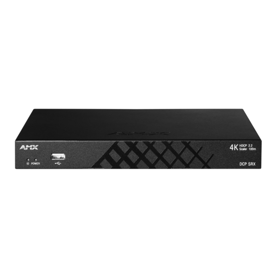
Page 8: Panel Overview
Item Name Description Connect to HDBT OUT of any HDBT transmitter or DCP-MTX HDBT IN or another DCP-SRX. Connects to a controllable device, e.g. projector, for RS232 RS232 pass-through control. Connects to a LAN device, e.g. IP-based touch panel for LAN ETHERNET control. -
Page 9: Scaler Switch
5. SCALER SWITCH DCP-SRX installs a “SCALER” DIP switch at the rear panel for manual adjustment of the scaling output. By default, the SCALER switch is in “Auto Scaler” position (all switches are set to 0000 or upward). Users are allowed to set DCP-SRX to desired scaling output resolution by using the SCALER switch. -
Page 10: Application & Installation
MTX 1 to DCP-MTX 2); 2) Connect the rest DCP-MTXs through HDBT likewise. 3) Connect HDBT OUT of the first DCP-SRX to HDBT IN of the next (e.g. DCP- SRX 1 to DCP-SRX 2); 4) Connect the rest DCP-SRXs through HDBT likewise. - Page 11 “Start Sequence” to allocate IP addressing to each DCP device. 3. Connect source and display devices to DCP-MTXs. 4. Connect an HDMI display device to HDMI OUT of each DCP-SRX. If audio output is required, connect an audio system to AUDIO OUT of DCP-SRX. NOTE: •...
- Page 12 USER MANUAL DCP-SRX...
-
Page 13: Cec & Rs232 Auto Control
7. CEC & RS232 AUTO CONTROL DCP-SRX is embedded with a CEC controller and a RS232 controller. When CEC / RS232 Auto Control is switched on, DCP-SRX will detect the signal status and send CEC / RS232 command to power on or off the display connected. CEC / RS232 Auto Control of DCP-SRX can be configured through Web UI or Telnet. - Page 14 Start to countdown if (HDBT) no active input signal HDBaseT HDBaseT is detected DCP-SRX When active input signal Cancel countdown is inserted NOTE: • To realize CEC/RS232 Auto Control of DCP-SRX, please connect a display device which accepts CEC/RS232 command. USER MANUAL DCP-SRX...
-
Page 15: Set-Up & Control
8. SET-UP & CONTROL DCP-SRX is designed with ease of connection and control in mind. When the device is connected and powered on, you can choose the optimal way to control the unit at your convenience, either through the specifically designed web-based user interface or Telnet. -
Page 16: Control Through Web Ui
TIP: In case you forget the IP address or the login password newly changed for DCP-SRX, please reset the device using the “RESET” button. For more information, please go to “9. RESET”. 8.1.2 Control through WEB UI Web UI of DCP-SRX is comprised by four sections: Status, Configuration, Advanced, and Device List. - Page 17 Custom Web UI Logo Factory Default Change Password System Advanced Reboot System Enable (ON/OFF) Automatic Logout Delay Time Firmware Firmware (MCU & ARM & Scaler) Device 1 (Name, IP) Device List Device 2 (Name, IP) Device n (Name, IP) USER MANUAL DCP-SRX...
-
Page 18: Status
Device The Device sub-menu is used to perform the following functions: • • Device Name • Daisy-Chain Grouping • Network 1) ID The ID button is used to help located the DCP-SRX in a DCP connection system. USER MANUAL DCP-SRX... - Page 19 Click to turn ON the ID button, then check the ID LED of each DCP-SRX or DCP device. The device with a flashing ID LED is the one accessed through Web UI. 2) Device Name The Device Name allows you to redefine the name of DCP-SRX or a DCP device in case multiple DCP devices are connected.
- Page 20 4) Network The Network section allows you to set up the IP mode of the DCP-SRX to either Static or DHCP. By default, DCP-SRX is shipping in Static mode, with default IP address of 192.168.1.122, Netmask of 255.255.0.0 and Gateway of 192.168.1.1.
- Page 21 DCP-SRX is embedded with a CEC controller and will automatically power on/off the display connected to its HDMI OUT port when CEC Auto Control is switched on. Above all, for CEC control of DCP-SRX to be effective, the display connected should support CEC over HDMI.
- Page 22 2) RS232 Controller DCP-SRX incorporates a built-in RS232 controller and is able to power on or off the display connected to RS232 port by detecting the source status and then sending corresponding command to the display. • Baud Rate: Set the Baud Rate for the device connected to the RS232 port.
-
Page 23: Advanced
The Advanced section includes Welcome Menu, Password, System, Fireware and allows you to customize your own logo for your Web UI pages, set up a new login password, reset or reboot the DCP-SRX settings, enable/disable automatic logout from Web UI and upgrade firmware of your DCP-SRX device. - Page 24 SRX, please reset the device using the “RESET” button on the rear panel. For more information, please go to “9. RESET”. System The System section is for resetting and rebooting the DCP-SRX device as well as setting the Automatic Logout from the Web UI. 1) System The System sub-section is used for restoring the DCP-SRX to factory default settings or rebooting the system.
- Page 25 Step 2: Click “Browse” to search for the update file. Then click “Next” to start uploading the update files. NOTE: Please mind the suffix (.h00 / .h01 / .h02) of each update file and ensure each file goes to the correct data bank. Otherwise you may fail to start upgrading. USER MANUAL DCP-SRX...
- Page 26 Step 3: When uploading is done, the following appears. Click “Next” to start updating. Step 4: The MCU updating will take about two minutes. Step 5: When completed, the following window will appear. After completion, please reboot the device manually. USER MANUAL DCP-SRX...
- Page 27 Step 1: Click ARM “Update” button, then the following window will pop up. Step 2: Click “Browse” to search for the update file. Then click “Next” to start uploading the update files. Step 3: When uploading is done, the following appears. Click “Next” to start updating. USER MANUAL DCP-SRX...
- Page 28 Step 1: Open the chassis and find out the wire feet used for scaler updating (see 1, 2, 3 in the picture below). Short circuit the feet. Attach a USB flash drive (contains Scaler update file) to the USB connector on the front panel). USER MANUAL DCP-SRX...
-
Page 29: Device List
• Listed Device: Click to navigate to its Web UI page. 8.2 TELNET DCP-SRX can also be controlled by Telnet, a protocol that enables you to connected a remote or local computer with DCP-SRX over a TCP/IP network. USER MANUAL... - Page 30 (e.g. PC) and DCP-SRX has been configured correctely. For Telnet control, the two network parameters of DCP-SRX are required: • IP Address: DCP-SRX comes with a default IP address of 192.168.1.122 and may be changed after IP sequencing. Please use the one after IP sequencing. •...
-
Page 31: Reset
9. RESET DCP-SRX installs a physical RESET button on its rear panel and will restore the device settings and login password. To reset DCP-SRX: 1. Hold down the RESET button (rear panel) for at least 5 seconds using a paper clip. -
Page 32: Appendix: Api Command Set
Get current device subgroup status. Command: Command: CLED#T CLED1T Return: Return: CLED#T CLED1T Set ID LED Parameter: Description: ※ LED# : # = {0, 1} // {0, 1}:{off, on} Set ID is on. Description: Indicates my current location. USER MANUAL DCP-SRX... - Page 33 Command: CVMT CVMT Return: Audio Mute ON Return: CVMT CVMT Description: Description: Mute the output Mute the output Command: Command: CVUT CVUT Return: Return: Audio Mute OFF CVUT CVUT Description: Description: Un-mute the output Un-mute the output USER MANUAL DCP-SRX...
- Page 34 6:Fix 1920x1200@60 7:Fix 3840x2160@30 8:Fix 3840x2160@60 11: AUTO 1024x768@60 12: AUTO 1280x720@60 13: AUTO 1280x800@60 14: AUTO 1280x1024@60 15: AUTO 1920x1080@60 16: AUTO 1920x1200@60 17: AUTO 3840x2160@30 18: AUTO 3840x2160@60} Auto (preferred native timing of the display) USER MANUAL DCP-SRX...
- Page 35 SDSPT Return: Return: SDSPT( value ) SDSPT( 2 ) Get CEC POWER Delay Time Status Description: Parameter: ※ value = {0, 1, …30} CEC Power Delay Time is 2 min. Description: Get CEC POWER Delay Time Status. USER MANUAL DCP-SRX...
- Page 36 Command: CUPA#T CUPA1T Return: Return: CUPA#T CUPA1T Set UART Parity bit Parameter: Description: ※ UPA# : # = {0, 1, 2} // {0, 1, 2}:{null, UART Parity bit is odd. odd, even} Description: Set UART Parity bit USER MANUAL DCP-SRX...
- Page 37 Command: Command: CUAU#T CUAU1T Return: Return: CUAU#T CUAU1T Set UART Auto Power On/Off Parameter: Description: ※ UAU# : # = {0, 1} // {0, 1}:{off, on} Set UART Auto Power On. Description: Set UART Auto Power On/Off. USER MANUAL DCP-SRX...
- Page 38 Command: ~SYSR! ~SYSR! Return: Return: Factory Reset ~SYSR! ~SYSR! Description: Description: Reset system setting. Reset system setting. Command: Command: ~APP! ~APP! Return: Return: System Reboot ~APP! ~APP! Description: Description: Cause a warm reboot. Cause a warm reboot. USER MANUAL DCP-SRX...
- Page 39 Set DHCP IP Address. Set DHCP IP Address. Command: Command: SIPT SIPT Return: Return: GET IP Address SIPT( IP:xx.xx.xx.xx MASK:xx.xx.xx.xx ) SIPT( IP:192.168.2.128 MASK:255.255.255.0 ) Description: IPxx.xx.xx.xx = {ipaddress} Description: MASKxx.xx.xx.xx = {mask} Verify the static IP address USER MANUAL DCP-SRX...
- Page 40 © 2017 Harman. All rights reserved. ENZO, NetLinx, AMX, AV FOR AN IT WORLD, HARMAN, and their respective logos are registered trademarks of HARMAN. Oracle, Java and any other company or brand name referenced may be trademarks/registered trademarks of their respective companies.
Need help?
Do you have a question about the DCP-SRX and is the answer not in the manual?
Questions and answers