Table of Contents
Advertisement
Quick Links
Overview
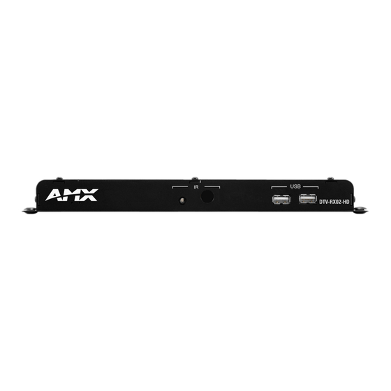
As part of an AMX TDS (Television Distribution System) installation, the DTV-RX02-HD
High-Definition Receiver (FG1411-02) is located at the display to receive an incoming digital
TV signal from a DTV Transmitter, and convert it to a compatible HD format for the display
(FIG. 1).
External IR Receiver socket
(front)
Analog audio Out (L/R)
CVBS digital video Out
Component video Out
(rear)
10/100 (RJ45) Ethernet
connector (to network)
FIG. 1
DTV-RX02-HD Receiver
Trademark Acknowledgement
The design of the DTV-RX02-HD was approved by Dolby™. Manufactured under license
from Dolby Laboratories. Dolby and the double-D symbol are trademarks of Dolby
Laboratories.
Product Specifications
DTV-RX02-HD Receiver
Dimensions (HWD):
1" x 10.5" x 4.25" (2.54 cm x 26.67 cm x 10.76 cm)
Weight:
0.90 lbs (0.41 kg)
Power:
• Input Voltage 12VDC
• Power Dissipation 6~10 Watts
Front Panel Components
IR Receiver:
For use with the DTV-RC01 Digital TV Remote Control (included).
External IR
Connects to the External IR Receiver (included).
Receiver Socket
USB Ports
not used
Rear Panel Connectors
10/100 (RJ45):
Standard 10/100 Network (RJ45) connector.
Note: The DTV-RX02-HD does not support PoE power.
AUDIO / VIDEO
• COMPONENT: 15-pin connector provides component video output.
OUT Connectors:
• CVBS: RCA connector provides composite video output.
• L / R Stereo: RCA connectors provide L/R analog audio output.
• SPDIF: RCA connector provides digital audio output.
• HDMI: HDMI connector provides HDMI video output.
RS232 (DB9):
Serial connector for local command line interface (RS232 only).
Mainly used for control of TV, and can be used for changing IP.
POWER:
Barrel plug accepts 12VDC power from the included power supply.
Note: This connector is intended to be used only with the provided
power supply.
Operating
• Temperature: 35°F - 95°F (5°C - 35°C)
Environment:
• Humidity: Max. relative humidity - 85% (non-condensing)
Certifications:
• CE
• FCC part 15 Class A
Included Accessories:
• 12 VDC Power Supply
• DTV-RC01 Digital TV Remote Control (FG1411-70)
• External IR Receiver (60-1411-01)
Other AMX Equipment:
• DTV-MA01 TDS Management Appliance (FG1412-01)
• DTV-TX01-DVB-T Transmitter (FG1410-01)
• DTV-TX02-DVB-S Transmitter (FG1410-02)
• DTV-TX03-US Transmitter (FG1410-03)
• CC-232 Serial Communication Cable (FG10-752-04)
Supported Output Resolutions
DTV-RX02-HD Receivers - Supported Output Resolutions
• 1920 x 1080p / 60Hz (*)
• 1920 x 1080i / 60Hz (*)
• 1280 x 720p / 60Hz (*)
• 480p / 60Hz
• 480i / 60Hz
Note: The asterisk (*) indicates dual output with HDMI/Component
Subtitle Support
DTV-RX02-HD Receivers do not support the display of subtitles.
DTV-RX02-HD
IR Receiver
SPDIF digital audio Out
HDMI video Out
RS232 Serial connector
(DB9: for local device control only)
PWR connector
• 1080p / 50Hz (*)
• 1080i / 50Hz (*)
• 720p / 50Hz (*)
• 576p / 50Hz (*)
• 576i / 50Hz (*)
AMX TDS System Description
The AMX TDS system can be deployed in any installation where digital A/V broadcast over IP
is desired, and delivers Digital TV and other encoded A/V signals to a number of TV sets, or
desktop PC's.
System Components
The AMX TDS system consists of several components, including a DTV-MA01 TDS
Management Appliance, Receiver (and IR Remote Controller), and Transmitter. See the AMX
TDS Operation/Reference Guide for details.
Network Considerations
Because of the high bandwidth associated with A/V distribution, the TDS system is typically
not used
managed via a separate IT infrastructure. However, content may be streamed over the main
network if desired. Consult your IT representative to determine the proper network
configuration for the TDS system.
The AMX TDS system transmits audio/video using IP multicast. In order for this to work
satisfactorily, it is vital that the network switches are multicast-enabled in order to prevent
unwanted flooding of traffic on the network.
•
Within the context of AMX TDS documentation. the term "Multicast-enabled" means
that all network switches carry out IGMP snooping, and one switch must function as the
IGMP querier.
•
AMX Digital TV supports version 2 of IGMP.
Front Panel Components
External IR Receiver Socket
Use the External IR Receiver socket on the front panel to connect the included External IR
Receiver (60-1411-01).
The IR Receiver provides wired IR control of the RX02.
IR Receiver
The IR Receiver on the front panel allows the DTV-RX02-HD to use the DTV-RC01 Digital TV
Remote Control (included) for channel selection and control of local monitor volume and
power.
Rear Panel Connectors
All connectors are located on the rear panel of the DTV-RX02-HD, for ease of installation and
easy access. Refer to FIG. 1 for the connector layout.
10/100 Port
The 10/100 (RJ45) port on the rear panel provides 10/100 BaseT network connectivity.
Network Port Pinouts and Signals
The following table lists the pinouts, signals, and pairing for the 10/100 Network port.
RJ45 Network Port Pinouts and Signals
Pin
Signals
1
TX +
2
TX -
3
RX +
4
no connection
5
no connection
6
RX -
7
no connection
8
no connection
Note: The maximum distance that a Receiver can be mounted from the Network Switch is
100m (328').
Consult the Network Administrator for correct cabling from the DTV-TX Transmitter onto the
network.
•
For remote connectivity, the Firewall may have to be configured to open port 2008 for
remote connectivity over UDP.
•
For remote connectivity, the Receivers will use ports 2008, 5000, 5001, 5002 and 5003
for remote connectivity over UDP.
Ethernet LEDs
L/A - Link/Activity LED
lights (green) when the
Ethernet cables are
connected and terminated
correctly.
FIG. 2
Ethernet LEDs
Default IP Address
By default, DTV Receivers are set to DHCP. See the Setting the Receiver's IP Address via
the RS 232 Port section for more information.
Audio Output Connectors
•
Analog: Standard red and white AUDIO RCA connectors provide analog stereo audio
output (White = Left, Red = Right).
•
Digital: The orange SPDIF RCA connector provides digital audio output.
Video Output Connectors
•
VGA: The 15-pin VGA connector provides Component video output.
•
CVBS: The yellow CVBS RCA connector provides Composite video output.
•
HDMI: The HDMI connector provides HDMI video output.
Installation Guide
Digital TV Receiver High Definition
Connections
Pairing
1 --------- 1
1 --------- 2
2 --------- 2
3 --------- 3
3 --------- 6
4 --------- 4
5 --------- 5
6 --------- 6
7 --------- 7
8 --------- 8
SPD - Speed LED
lights (yellow) when the
connection speed is 100 Mbps
and turns Off when speed is
10 Mbps.
Color
Orange-White
Orange
Green-White
Blue
Blue-White
Green
Brown-White
Brown
Advertisement
Table of Contents

Related Manuals for AMX DTV-RX02-HD


Summary of Contents for AMX DTV-RX02-HD
-
Page 1: Installation Guide
Product Specifications IR Receiver DTV-RX02-HD Receiver The IR Receiver on the front panel allows the DTV-RX02-HD to use the DTV-RC01 Digital TV Remote Control (included) for channel selection and control of local monitor volume and Dimensions (HWD): 1" x 10.5" x 4.25" (2.54 cm x 26.67 cm x 10.76 cm) power. - Page 2 ©2011 AMX. All rights reserved. AMX and the AMX logo are registered trademarks of AMX. AMX reserves the right to alter specifications without notice at any time. 3000 RESEARCH DRIVE, RICHARDSON, TX 75082 • 800.222.0193 • fax 469.624.7153 • technical support 800.932.6993 • www.amx.com...
Need help?
Do you have a question about the DTV-RX02-HD and is the answer not in the manual?
Questions and answers