CHIEF PF2 Series Installation Instructions Manual
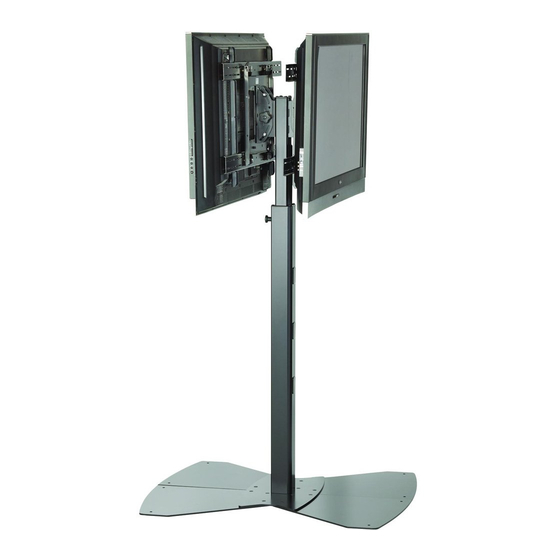
Single and dual display floor stands
Hide thumbs
Also See for PF2 Series:
- Installation instructions manual (12 pages) ,
- Installation instructions manual (12 pages) ,
- Installation instructions manual (12 pages)

Related Manuals for CHIEF PF2 Series


Summary of Contents for CHIEF PF2 Series
- Page 1 I N S T A L L A T I O N I N S T R U C T I O N S Single and Dual Display Floor Stands MF1, MF2, PF1, PF2 Series...
-
Page 2: Important Warnings And Cautions
Chief® and ClickConnect™ are registered trademarks of Reinforce the structure as required before installing the Milestone AV Technologies. All rights reserved. - Page 3 Installation Instructions MF1, MF2, PF1, PF2 Series DIMENSIONS MF1, MF2 PF1, PF2...
- Page 4 Installation Instructions MF1, MF2, PF1, PF2 Series LEGEND Tighten Fastener Pencil Mark Apretar elemento de fijación Marcar con lápiz Befestigungsteil festziehen Stiftmarkierung Apertar fixador Marcar com lápis Serrare il fissaggio Segno a matita Bevestiging vastdraaien Potloodmerkteken Serrez les fixations Marquage au crayon...
-
Page 5: Tools Required For Installation
Installation Instructions MF1, MF2, PF1, PF2 Series TOOLS REQUIRED FOR INSTALLATION 1/4" (To remove base 3/16" plates from packaging) (included) PARTS [PF Head Assemblies] D (1) D1 (1) A (1) B (1) (Single Display Models Only) F (1) E (1) - Page 6 MF1, MF2, PF1, PF2 Series Installation Instructions ASSEMBLY Attach top base section (A) to the center post (F) using four 5/16-18 x 1-1/2" button head cap screws (N) and four 5/16" flat washers (Q). (See Figure 2) CAUTION: Attachment holes may be damaged if a power drill is used to insert button head cap screws.
- Page 7 Installation Instructions MF1, MF2, PF1, PF2 Series Gather stand base pieces B and C (2) as shown in Figure 4 IMPORTANT ! : Press cable tie tab to loosen and and push them together until the edges meet. remove cable tie from around knob post. (See Figure )
- Page 8 MF1, MF2, PF1, PF2 Series Installation Instructions Attaching Single Head Assembly IMPORTANT ! : When attaching head assembly ensure that the ClickConnect lock is at TOP of head assembly, (M) x 4 and bracket tabs slide into the stand assembly. (See Figure 8) Slide head assembly (D) or (E) into the stand assembly.
- Page 9 Installation Instructions MF1, MF2, PF1, PF2 Series Adjust the stand to the desired height by slightly lifting the head assembly, pulling out knob on the center post and turning 90 in either direction to disengage the locking mechanism. (See Figure 11)
- Page 10 MF1, MF2, PF1, PF2 Series Installation Instructions Tilting Display (Rear (Front view The display(s) can be tilted up to 15 either backward or view of of center post) forward from a straight upright position. In a dual stand, the center post) tilting is only restricted by the size of the display.
- Page 11 Installation Instructions MF1, MF2, PF1, PF2 Series WARNING: STAND CAN TIP OVER RESULTING IN RISK Remove bolt OF INJURY. Never move the stand when displays are or padlock attached. Never push against the stand. if used Removing Display(s) from Stand Remove bolt or padlock from faceplate (if used).
- Page 12 MF1, MF2, PF1, PF2 Series Installation Instructions USA/International A 8401 Eagle Creek Parkway, Savage, MN 55378 P 800.582.6480 / 952.894.6280 F 877.894.6918 / 952.894.6918 Europe A Fellenoord 130 5611 ZB EINDHOVEN, The Netherlands P +31 (0)40 2668620 Chief Manufacturing, a products division...
Need help?
Do you have a question about the PF2 Series and is the answer not in the manual?
Questions and answers