Advertisement
Quick Links
Advertisement

Subscribe to Our Youtube Channel
Related Manuals for CHIEF PAC527 Series


Summary of Contents for CHIEF PAC527 Series
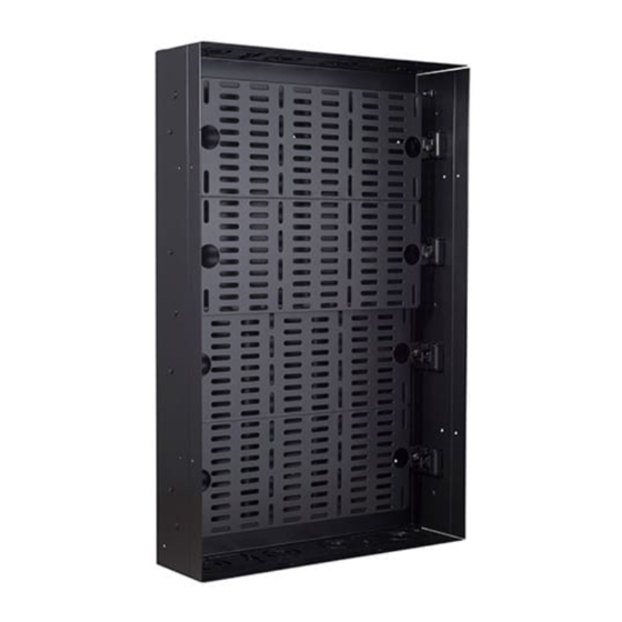
- Page 1 PDF provided by Conference Room AV Chief PAC527FBP6 XL In-Wall Storage Box with 6-Receptacle Filter and Surge...
- Page 2 I N S T A L L A T I O N I N S T R U C T I O N S PAC527 PAC527F-KIT PAC527FxP4 PAC527F PAC527CVR-KIT PAC527FxP6 PACPL1 PAC527FC In-Wall Box and Accessories PAC527 Series...
-
Page 3: Important Safety Instructions
For indoor use only. ACCESSORY: AN ACCESSORY is the secondary Chief product which is attached to a primary Chief product, and may IMPORTANT ! : The PAC527 accessory is designed to be have a component attached or setting on it. - Page 4 Installation Instructions PAC527 Series ADDITIONAL SAFETY INSTRUCTIONS CAUTION SPECIFIC TO PAC527FxP4 / PAC527FxP6 This equipment must be installed and assembled by qualified service personnel in accordance with local building and electrical codes. READ ALL INSTRUCTIONS BEFORE USING THIS PRODUCT!!!! NOTE: Knockouts are provided for ease of installation.
- Page 5 Installation Instructions PAC527 Series LEGEND Tighten Fastener Pencil Mark Apretar elemento de fijación Marcar con lápiz Befestigungsteil festziehen Stiftmarkierung Apertar fixador Marcar com lápis Serrare il fissaggio Segno a matita Bevestiging vastdraaien Potloodmerkteken Serrez les fixations Marquage au crayon Loosen Fastener Drill Hole Aflojar elemento de fijación...
-
Page 6: Tools Required For Installation
PAC527 Series Installation Instructions TOOLS REQUIRED FOR INSTALLATION 3/16" OPTIONAL 1/4" PARTS INCLUDED E (1) [PAC527] B (8) PAC527 06-32" A (4) 1/4 x 2-1/2" D (4) F (1) C (8) 3/8" [Template/ 06 x 3/8" Temporary Cover] G (1) - Page 7 Installation Instructions PAC527 Series PARTS - continued J (1) [PAC527FxP4] PAC527FxP4 B (8) 06-32" A (4) 1/4 x 2-1/2" D (4) F (1) C (8) 3/8" [Template/ 06 x 3/8" Temporary Cover] K (1) [PAC527FxP6] B (8) PAC527FxP6 06-32" A (4) 1/4 x 2-1/2"...
-
Page 8: Additional Information
PAC527 Series Installation Instructions OPTIONAL PARTS PER CUSTOM CONFIGURATION (NOT INCLUDED) Conduit connectors Electrical Narrow Handy Box 3" x 2" Steel Old outlet Cover, Duplex Work Switch Box Raco #864 or (2" deep) equivalent Raco #420 or equivalent Conduit pipe 1/2", 1" or 1-1/4"... - Page 9 PAC527 Series Installation Instructions INSTRUCTIONS FOR PAC527FxP4 / • (8) Notwithstanding Sub-rules (6) and (7), the bonding jumper, in the case of receptacles having PAC527FxP6 Only grounding terminals isolated from the mounting strap required for special equipment, shall be Isolated Ground Receptacle permitted to be extended directly back to the distribution panel.
- Page 10 Installation Instructions PAC527 Series Wire the outlet box(es) as required. Refer to Table 1 and Table 2 for input and output specifications. (See Figure 2) (PAC527FxP4 shown as example) Table 1: Input Specifications Input Input voltage, frequency 125 V AC, 60 Hz...
- Page 11 PAC527 Series Installation Instructions PAC527 Site Preparation Using a level, draw a horizontal line at the lower edge of the install site. (See Figure 4) Create an exploratory hole to confirm edge of the studs. Using the line drawn in Step 1 as lower edge and placing...
- Page 12 Installation Instructions PAC527 Series Loosely attach required conduit and conduit connectors, NOTE: If installing in a stud wall BEFORE the drywall is switch boxes, outlets, etc (not included) to PAC527 to installed, remove outer flange from PAC527 before enable fitting into the wall opening. (See Figure 7) installing the PAC527.
- Page 13 PAC527 Series Installation Instructions Installing Backplanes (PACPL1) PACPL1 ONLY: Loosely install two 10-24 x 3/8" Phillips external tooth screws (V) into each backplane half. (See IMPORTANT ! : The backplanes ship installed in the Figure 11) PAC527 / PAC527F / PAC527FC / PAC527FxP4 /...
- Page 14 Installation Instructions PAC527 Series PAC527F-KIT PAC527CVR-KIT Loosely install eight 10-24 x 1/4" Phillips head screws with Break away the tab(s) on the cover (N) to allow wire exit external teeth (M) into holes in PAC527 sides. (See Figure 14) from the PAC527, and to meet ventilation needs of the components.
- Page 15 PAC527 Series Installation Instructions DIMENSIONS PAC527 0.50 1.50 0.20 5.2 12.7 38.1 X 0.95 24.2 TYPICAL TYPICAL 1.00 25.4 FINGER HOLD BREAK-OFF LINE 1.25 10.00 31.8 254.0 TYPICAL 5.00 127.0 12.00 304.8 13.21 335.6 NOTE: DIMENSIONS: INCHES SCREWS ARE THREADED TO THE BACKPLANE...
- Page 16 Installation Instructions PAC527 Series DIMENSIONS - continued PAC527F 0.50 1.50 0.20 5.2 12.7 38.1 X 0.95 24.2 TYPICAL TYPICAL 1.00 25.4 FINGER HOLD BREAK-OFF LINE 1.25 10.00 31.8 254.0 TYPICAL 5.00 127.0 12.00 304.8 13.21 335.6 NOTE: DIMENSIONS: INCHES SCREWS ARE THREADED TO THE BACKPLANE...
- Page 17 PAC527 Series Installation Instructions DIMENSIONS - continued 14.25 PAC527FC 362.0 THREE 3.94 6.38 1.75 BACKPLANE 100.0 161.9 44.5 DEPTH POSITIONS 1.00 3.88 AVAILABLE 25.4 98.4 1.37 0.25 34.8 2.88 15.40 73.0 391.1 5.00 127.0 5.00 23.26 22.00 20.00 127.0 BREAK-OFF 590.9...
- Page 18 Installation Instructions PAC527 Series DIMENSIONS - continued PAC527FxP4 PAC527FxP6 PAC527FxP4 PAC527FxP6 PAC527FxPx *SEE PAC527F FOR ADDITIONAL BOX DIMENSIONS* AC LINE POWER CONDITIONER 125 V~, 60 Hz, 15 A 4x14 AWG STRANDED WIRE W/ ISOLATED GROUND SURGE PROTECTION 15.40 EMI/RFI FILTERING 391.1...
- Page 19 PAC527 Series Installation Instructions DIMENSIONS - continued PAC527F-KIT 0.43 4.75 11.0 120.7 15.40 391.1 21.76 552.8 23.26 590.9 13.90 353.0 DIMENSIONS: INCHES [MILLIMETERS] PAC527CVR-KIT 13.38 339.7 1.50 38.0 21.75 552.5 3.63 0.69 92.1 17.5 5.00 127.0 DIMENSIONS: INCHES 13.81 [MILLIMETERS]...
- Page 20 Installation Instructions PAC527 Series DIMENSIONS - continued PACPL1 0.95 0.50 1.50 24.2 12.7 38.1 0.20 TYPICAL TYPICAL 1.00 25.4 FINGER HOLD BREAK-OFF LINE 1.25 10.00 31.8 254.0 TYPICAL 5.00 127.0 12.00 304.8 13.21 335.6 NOTE: DIMENSIONS: INCHES SCREWS ARE THREADED TO THE BACKPLANE...
- Page 21 Europe A Franklinstraat 14, 6003 DK Weert, Netherlands P +31 (0) 495 580 852 F +31 (0) 495 580 845 Chief, a products division of Asia Pacific A Office No. 918 on 9/F, Shatin Galleria Milestone AV Technologies 18-24 Shan Mei Street...
Need help?
Do you have a question about the PAC527 Series and is the answer not in the manual?
Questions and answers