Table of Contents
Advertisement
I N S T A L L A T I O N I N S T R U C T I O N S
Instrucciones de instalación
Installationsanleitung
Instruções de Instalação
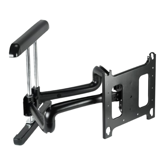
Large Flat Panel Dual Arm Wall Mount
Istruzioni di installazione
Installatie-instructies
Instructions d´installation
Spanish Product Description
German Product Description
Portuguese Product Description
Italian Product Description
Dutch Product Description
French Product Description
PDR Series
Advertisement
Table of Contents

Related Manuals for CHIEF PDR Series


Summary of Contents for CHIEF PDR Series
- Page 1 Instrucciones de instalación Istruzioni di installazione Installationsanleitung Installatie-instructies Instruções de Instalação Instructions d´installation Large Flat Panel Dual Arm Wall Mount Spanish Product Description German Product Description Portuguese Product Description Italian Product Description Dutch Product Description French Product Description PDR Series...
-
Page 2: Installation Instructions
Reinforce the structure as required before installing the component. The wall to which the mount is being attached Chief® is a registered trademark of Milestone AV Technologies. may have a maximum drywall thickness of 5/8" (1.6cm). All rights reserved. - Page 3 Installation Instructions PDR Series DIMENSIONS -- cont’d Tilt Adjustment * Unit Depth Extended Retracted [86] 3.40 1003 37.00 39.50 *The range of adjustment will vary with different weight and depth screens Highest Height Setting 2.81 1.68 Lowest Height Setting 90°...
- Page 4 PDR Series Installation Instructions LEGEND Tighten Fastener Pencil Mark Apretar elemento de fijación Marcar con lápiz Befestigungsteil festziehen Stiftmarkierung Apertar fixador Marcar com lápis Serrare il fissaggio Segno a matita Bevestiging vastdraaien Potloodmerkteken Serrez les fixations Marquage au crayon Loosen Fastener Drill Hole Aflojar elemento de fijación...
-
Page 5: Tools Required For Installation
Installation Instructions PDR Series TOOLS REQUIRED FOR INSTALLATION 7/32" (5.5mm) 9/16" PARTS NOTE: Listed PSBU interface bracket provided with Listed Model PDRUS/B, but not shown. B (2) [Cover] A (1) [PDR assembly] C (2) [End cap] D (2) [End cap]... -
Page 6: Mount Installation
PDR Series Installation Instructions MOUNT INSTALLATION Place two installation washers (G) over two lag bolts (H). (See Figure 2) Installing Mount to Wall 10. Install two 5/16" x 3-1/2" lag bolts (H) through mounting holes in lower wall channel and into pilot holes. (See Figure 2) 11. -
Page 7: Mounting The Display
Installation Instructions PDR Series WARNING: IMPROPER INSTALLATION CAN LEAD TO MOUNT FALLING CAUSING SEVERE PERSONAL INJURY OR DAMAGE TO EQUIPMENT. Make sure mounting buttons on display are properly seated in mounting holes in faceplate. Move mount faceplate to extended position by grasping faceplate and pulling outward away from wall. -
Page 8: Cable Management
PDR Series Installation Instructions cable clamps Figure 7 Cable Management Centris Select WARNING: Adjustment Knob IMPROPER INSTALLATION CAN LEAD TO SERIOUS PERSONAL INJURY OR DAMAGE TO EQUIPMENT! Make sure cables do not run through pinch points. Loosen front and rear cable clamps on top arm. -
Page 9: Swing Arm Adjustments
Installation Instructions PDR Series Lateral Tilt Tension Adjustment After the top and bottom mounting brackets have been installed between two wood studs 16” on center, the swing arms can be adjusted or moved off center, depending on the location of the... -
Page 10: Swing Arm Tension Adjustment
PDR Series Installation Instructions Locate the adjustment insert (F) and wrench (E) provided with the mount. WARNING: The next step will release the arm assembly Place adjustment insert into socket head cap screw located from the mount. The arms and plate may fall if you are not at swing arm pivot point. -
Page 11: Removing Display From Mount
Installation Instructions PDR Series Removing Display from Mount Remove bolt or padlock from faceplate (if used). Remove bolt NOTE: or padlock The pin may have been used as a more permanent if used locking device. If so, remove nut and pin and move from the lower holes to the upper holes. - Page 12 Europe A Franklinstraat 14, 6003 DK Weert, Netherlands P +31 (0) 495 580 852 F +31 (0) 495 580 845 Chief Manufacturing, a products division Asia Pacific A Office No. 1 on 12/F, Shatin Galleria of Milestone AV Technologies 18-24 Shan Mei Street...
Need help?
Do you have a question about the PDR Series and is the answer not in the manual?
Questions and answers