Table of Contents
Advertisement
Advertisement
Table of Contents

Related Manuals for Keiser Keiser 300


Summary of Contents for Keiser Keiser 300
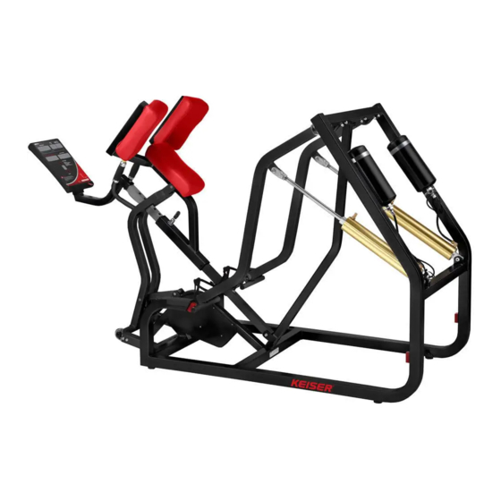
- Page 1 Keiser 300 / Air 300 Parts and Maintenance Manual...
-
Page 2: Table Of Contents
Table of Contents Introduction – How it Works Preventive Maintenance Troubleshooting Air Hoses and Fittings Filter Valves Cylinders Mufflers Fasteners Arm Locks Bearings Hand Grips Upholstery – Decals Parts Identification SAFETY CAUTIONS: We’ve put a number of safety cautions in this book. We use the word CAUTION to tell you about things that could cause bodily injury to persons on or around the equipment if you were to ignore the warning. -
Page 4: Introduction - How It Works
K300 – HOW IT WORKS Two basic systems are used to operate the KEISER 300 series exercise machines. On machines that exercise the muscle groups of the upper body, the resistance is controlled by means of foot pedals mounted on the base of the machine. Thumb buttons in the handles operates machines for lower body muscle groups. -
Page 7: Air Hoses And Fittings
If the leak is at a fitting, first tighten the nut about one-quarter (1/4) of a turn. Test the connection again. If the fitting still leaks, the nut must be replaced. In most cases the air hose should be long enough to allow this; if not, order a new air hose from KEISER. To install a new nut: TOOLS REQUIRED: adjustable wrench and a sharp knife 1. - Page 8 If the feed hose must be repaired or replaced, follow this procedure: 1. To replace hose, unscrew the compress-align nuts on both ends and remove the hose (new hoses and compress-align nuts are available from KEISER). 2. To shorten the hose, unscrew chrome compress-align nut from the quick-disconnect and cut the hose to the desired length.
-
Page 9: Filter
FILTER The air filter keeps moisture and dirt out of the cylinders and other components. The filter bowl must be kept free of moisture. Filter bowls that fill quickly with water indicate a problem with the air dryer. If your air system does not include a dryer, the filters on all machines must be checked and/or drained daily. -
Page 10: Valves
VALVES The valves in the pedals or handles can be removed for service or repair. Always unplug the quick-disconnect from the air system and decrease the resistance to zero before working on the valves. The following groups of machines state the type of valve and its maintenance procedures. - Page 11 3. Rest the valve housing on the open jaws of a vise and drive out the spring pin with a hammer and 3/16-drift punch (see illustration below). When the punch is removed, the spool can be removed as shown. 4. Remove the O-rings off the spool. CAUTION : DO NOT CUT SPOOL! CUTS IN A SPOOL ARE AREAS FOR POSSIBLE AIR LEAKS.
- Page 12 8. Replace the valve in the machine and remount the end cap on the end of the handle (if you have any questions on the preceding steps, please contact our service department). SEATED CHEST PRESS, LATERAL SHOULDER RAISE, MILITARY PRESS, TRICEP, AND SEATED BUTTERFLY NOTE: Machines shipped before October, 1985 have nuts and bolts holding the valves in place.
- Page 13 2. Loosen the adjusting screw behind the pedal. Hold the nuts on top of the valve with a 3/8 open-end wrench and remove the screw with a 5/16 wrench or socket. The valve can now be lifted off the link, and the valve cartridge removed for service or replacement.
-
Page 14: Cylinders
CYLINDERS Three types of cylinders are used on K300 series machines: 2 ½ “ x 7” = Part #:11-5317 2 ½ “ x 12”= Part #:13-5316 4” x 12”= Part #:15-5314 Maintenance procedures are the same for all three types of cylinders. TOOLS REQUIRED: adjustable wrench, 5/16 or ¼... - Page 15 TO REPLACE THE CYLINDER: 1. Put a drop of oil on the bearings and remount the cylinder. Tighten all nuts securely. 2. Reattach the air hose. Tighten the nut finger-tight, plus ¼ turn. Plug in the quick- disconnect and check for air leaks. If the fitting leaks, tighten the nut another ¼ turn. If the leak persists, replace the nut.
- Page 16 6. Clean wear the strip grooves and apply a moderate coat of “Hydrotex MT-55” light grease (available from KEISER) to hold wear strips in place during assembly. Lightly coat the bore, cup seal, piston and wear strips with MT-55 light grease.
-
Page 17: Mufflers
1. Hold the clevis in position with a wrench as shown (1) and loosen the lock nut. NOTICE: LOOSENING THE LOCK NUT WITHOUT HOLDING THE CLEVIS CAN DAMGE THE BUSHINGS, CLEVIS AND THE CYLINDER ROD. 2. Adjust the rod length (2) as required. 3. -
Page 18: Fasteners
FASTENERS NUTS AND BOLTS Tightness of nuts and bolts should be checked monthly. Main frame bolts are generally held in place through an internal mounting tube (see illustration). These bolts should be tight (35-40 ft.-lbs.). Other bolts should not be tightened any more than necessary to keep them from turning freely. -
Page 19: Arm Locks
3. Remove the shaft from the bracket or the collar from the shaft, and tap the spring pin through and out of the shaft. NOTICE: ALWAYS REMOVE THE PIN FROM THE SHAFT IMMEDIATELY. ACCIDENTAL INSTALLATION OF A SECOND PIN WILL DAMAGE THE MACHINE. SPRING PIN REPLACEMENT: 1. - Page 20 REMOVING THE SHAFT: 1. Pry off the plastic cap covering the locking sleeve and spring pin. On the Seated Chest Press and Upper Back, this is the middle of the three square tubes. On the Military Press and Tricep, it is the outside tube. This cap must be replaced with a new part.
-
Page 21: Bearings
BEARINGS The ½, 5/8, and 1 inch flange bearings must be lubricated every 3 months. Using SAE 30 wt. Motor oil, put one drop on the exposed portion of each bearing. Move the machine through its range to work the oil in, then wipe the area around it free of exposed oil. T-88 REMOVAL AND REPLACEMENT CAUTION: THIS PROCEDURE REQUIRES A HIGH QUALITY, HARDENED ¼... - Page 22 (FHHS) screw. These bearings are permanently lubricated at KEISER and do not need any other lubrication. The T-88 bearing assembly should be checked weekly, and adjusted slightly tighter if the arms have excessive side-play.
-
Page 23: Hand Grips
LPS cleaner/degreaser (available at auto parts and hardware stores). THUMB BUTTON GRIP CAUTION: USE KEISER GRIPS ON KEISER MACHINES ONLY! USING GRIPS FROM ANY OTHER PRODUCTS MAY CAUSE SERIOUS INJURY. 1. Read all the instructions first before beginning any steps. - Page 24 5. Replace the end cap and plastic button on the new thumb button assy, rotate the end cap until the “+” or “-“ indicator is facing towards the user. Using the 5/64” allen wrench, tighten the set crews ¼ to ¾ of a turn past finger tight (Do not over tighten). 6.
-
Page 25: Upholstery - Decals
Remove the bolts holding the cushion to the frame and turn it around. If the upholstery is worn or damaged, the cover can be replaced at a lower cost than replacing the whole cushion. Contact KEISER for details. DECAL REMOVAL AND REPLACEMENT Damaged decals can be removed by simply peeling them off the surface. -
Page 26: Parts Identification
PARTS IDENTIFICATION Part numbers shown in this manual are unique to KEISER equipment. Six-digit numbers are KEISER-built parts, and can only be obtained through KEISER SPORTS HEALTH EQUIPMENT. See the back of the maintenance manual or check the website for fax and telephone numbers. -
Page 27: Leg Extension
NOTICE: CYLINDERS ARE FACTORY-ADJUSTED AND REQUIRE NO FURTHER ADJUSTMENT UNLESS THEY ARE REPLACED. Please contact KEISER if you have any questions concerning adjustments or repairs. 1. Decrease the resistance to zero. 2. Check the exercise arms for side play as described in the Maintenance Manual (pg. -
Page 28: Leg Curl
NOTICE: CYLINDERS ARE FACTORY-ADJUSTED AND REQUIRE NOT FURTHER ADJUSTMENT UNLESS THEY ARE REPLACED. Please contact KEISER if you have any questions concerning adjustments or repairs. 1. Decrease the resistance to zero. 2. Check the exercise arms for side play as described in the Maintenance Manual (pg. - Page 29 NOTICE: CYLINDERS ARE FACTORY-ADJUSTED AND REQUIRE NO FURTHER ADJUSTMENT UNLESS THEY ARE REPLACED. Please contact KEISER if you have any questions concerning adjustments or repairs. 1. Check the condition of the rubber crutch tips that the exercise arms rest against.
-
Page 30: Lateral Shoulder Raise
NOTICE: CYLINDERS ARE FACTORY-ADJUSTED AND REQUIRE NO FURTHER ADJUSTMENT UNLESS THEY ARE REPLACED. Please contact KEISER if you have any questions concerning adjustments or repairs. 1. Check the condition of the rubber crutch tips that the exercise arms rest against. - Page 31 CYLINDER ADJUSTMENT NOTICE: CYLINDERS ARE FACTORY-ADJUSTED AND REQUIRE NO FIRTHER ADJUSTMENT UNLESS THEY ARE REPLACED. Please contact KEISER if you have any questions concerning adjustments or repairs. 1. Check the condition of the rubber crutch tips that the exercise arms rest against.
- Page 32 the adjusting drag link, bottom. Drive the pin into the adjusting drag link, bottom, through the hole in the adjusting drag link, top. The spring pin should stick out 1/16” from each side of the adjusting drag link, bottom. 2. To install the spring pin 3/16 X 7/8 (item # 2) in the exercise arm mount (item # 4), line up the hole in the exercise arm mount with the hole in the exercise arm pivot shaft (item # 13).
-
Page 33: Military Press
NOTICE: CYLINDERS ARE FACTORY-ADJUSTED AND REQUIRE NO FURTHER ADJUSTMENT UNLESS THEY ARE REPLACED. Please contact KEISER if you have any questions concerning adjustments or repairs. 1. Check the condition of the rubber crutch tips that the exercise arms rest against. - Page 34 NOTICE: CYLINDERS ARE FACTORY-ADJUSTED AND REQUIRE NO FURTHER ADJUSTMENT UNLESS THEY ARE REPLACED. Please contact KEISER if you have any questions concerning adjustments or repairs. 1. Check the condition of the rubber crutch tips that the exercise arms rest against.
-
Page 35: Shoulder Shrug
NOTICE: CYLINDERS ARE FACTORY-ADJUSTED AND REQUIRE NO FURTHER ADJUSTMENT UNLESS THEY ARE REPLACED. Please contact KEISER if you have any questions concerning adjustments or repairs. 1. Check the condition of the rubber crutch tips that the exercise arms rest against. - Page 36 NOTICE: CYLINDERS ARE FACTORY-ADJUSTED AND REQUIRE NO FURTHER ADJUSTMENT UNLESS THEY ARE REPLACED. Please contact KEISER if you have any questions concerning adjustments or repairs. 1. Check the condition of the rubber crutch tips that the exercise arms rest against.
- Page 37 NOTICE: CYLINDERS ARE FACTORY-ADJUSTED AND REQUIRE NO FURTHER ADJUSTMENT UNLESS THEY ARE REPLACED. Please contact KEISER if you have any questions concerning adjustments or repairs. 1. Check the condition of the rubber crutch tips that the exercise arms rest against.
- Page 38 NOTICE: CYLINDERS ARE FACTORY-ADJUSTED AND REQUIRE NO FURTHER ADJUSTMENT UNLESS THEY ARE REPLACED. Please contact KEISER if you have any questions concerning adjustments or repairs. The Lat Pull Down cylinder is properly adjusted when 10 threads are visible on the cylinder rod above the jam nut (pg.
- Page 39 NOTICE: CYLINDERS ARE FACTORY-ADJUSTED AND REQUIRE NO FURTHER ADJUSTMENT UNLESS THEY ARE REPLACED. Please contact KEISER if you have any questions concerning adjustments or repairs. 1. Check the condition of the rubber crutch tips that the exercise arms rest against.
- Page 40 NOTICE: CYLINDERS ARE FACTORY-ADJUSTED AND REQUIRE NO FURTHER ADJUSTMENT UNLESS THEY ARE REPLACED. Please contact KEISER if you have any questions concerning adjustments or repairs. 1. Check the condition of the rubber crutch tips that the exercise arms rest against.
-
Page 41: Leg Press
NOTICE: CYLINDERS ARE FACTORY-ADJUSTED AND REQUIRE NO FURTHER ADJUSTMENT UNLESS THEY ARE REPLACED. Please contact KEISER if you have any questions concerning adjustments or repairs. 1. Check the condition of the rubber crutch tips that the exercise arms against. These must not be worn or damaged in any way. - Page 42 NOTICE: CYLINDERS ARE FACTORY-ADJUSTED AND REQUIRE NO FURTHER ADJUSTMENT UNLESS THEY ARE REPLACED. Please contact KEISER if you have any questions concerning adjustments or repairs. 1. Decrease the resistance to zero. 2. Pull up on the rod until the cam follower touches the cam. With no machine resistance, check the feel of the movement of the machine.
- Page 43 NOTICE: CYLINDERS ARE FACTORY-ADJUSTED AND REQUIRE NO FURTHER ADJUSTMENT UNLESS THEY ARE REPLACED. Please contact KEISER if you have any questions concerning adjustments or repairs. 1. Check the condition of the rubber crutch tips that the exercise arms rest against.
- Page 44 NOTICE: CYLINDERS ARE FACTORY-ADJUSTED AND REQUIRE NO FURTHER ADJUSTMENT UNLESS THEY ARE REPLACED. Please contact KEISER if you have any questions concerning adjustments or repairs. 1. Check the condition of the rubber crutch tips that the lever arms rest against. These must not be worn or damaged in any way.
- Page 45 5. With the resistance slightly greater, do a few repetitions, paying particular attention to the feel of the exercise at the very beginning of the stroke. A sticky or hesitant feel at the start could indicate a “bottomed-out” cylinder (when the piston is up against the end housing).
- Page 46 CYLINDER ADJUSTMENT NOTICE: CYLINDER ARE FACTORY-ADJUSTED AND REQUIRE NO FURTHER ADJUSTMENT UNLESS THEY ARE REPLACED. Please contact KEISER if you have any questions concerning adjustments or repairs. 1. Release all of the air from the machine until the exercise arms lowers to the floor.
Need help?
Do you have a question about the Keiser 300 and is the answer not in the manual?
Questions and answers