Table of Contents
Advertisement
Quick Links
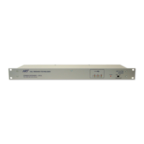
Model U97-ULTRA
All-in-One UTP Console Extender
Dual Video, Audio, RS-232, with
General Purpose USB, and up to 2 Direct USB Extensions
CUSTOMER
Order toll-free in the U.S. 800-959-6439
SUPPORT
FREE technical support, Call 714-641-6607 or fax 714-641-6698
INFORMATION
Mail order: Hall Research, 1163 Warner Ave. Tustin, CA 92780, CA 92704
Web site: www.hallresearch.com
UMA1158 Rev. D
Advertisement
Table of Contents

Subscribe to Our Youtube Channel
Related Manuals for Hall Research Technologies U97-ULTRA


Summary of Contents for Hall Research Technologies U97-ULTRA
- Page 1 General Purpose USB, and up to 2 Direct USB Extensions CUSTOMER Order toll-free in the U.S. 800-959-6439 SUPPORT FREE technical support, Call 714-641-6607 or fax 714-641-6698 INFORMATION Mail order: Hall Research, 1163 Warner Ave. Tustin, CA 92780, CA 92704 Web site: www.hallresearch.com UMA1158 Rev. D...
- Page 3 TRADEMARKS USED IN THIS MANUAL logo are trademarks of Hall Research Inc. Hall Research, HR, and the Windows™ is a trademark of Microsoft Corporation. Any other trademarks mentioned in this manual are acknowledged to be the property of the trademark owners.
-
Page 4: Table Of Contents
Model U97-ULTRA Table of Contents About this User’s Manual ..................5 1.0 General ....................... 6 1.1 Catx Cable Requirements ................6 1.2 RJ45 Port Functions ................... 7 1.3 User I/O Connector Descriptions ............... 7 1.4 Features ...................... 9 2. Installation ......................10 2.1 Connecting the Sender to the PC .............. -
Page 5: About This User's Manual
Sender (Local) Unit - Peripheral Extender with 2 direct USB U97-ULTRA -2S Ports (DR1 & DR2) These products are manufactured by Hall Research to highest quality control standards. All units are fully tested (including Hi-Pot leakage), undergone 24 to 48 hours of burn-in, and re-tested prior to delivery. -
Page 6: General
Model U97-ULTRA 1.0 General U97-ULTRA-2 kit is used to extend Dual Display PC Video, Stereo Audio, RS-232, and up to 3 independent USB ports to a remote location up to 400 feet away on any Category Cable (CAT5e/6 etc). A block diagram of the system is shown below. -
Page 7: Rj45 Port Functions
Powered outputs (for driving passive speakers). The DB15 audio I/O allows interface with not only line-level 3.5 mm mini-stereo audio sources (using adapter cable available from Hall Research), but it also provides a more reliable and secure means for the audio connection through use of gold-plated D-Sub connector with jack screws. - Page 8 Model U97-ULTRA general-purpose USB ports support any type of low-speed or high-speed USB devices. AUX and AUX are typically used for touch screen displays, but support all other USB devices as well. DR1 & DR2 – These are two “Direct” extension USB ports. The corresponding ...
-
Page 9: Features
Console Extender 1.4 Features • Combines the functions of Hall Research Models U97-H2, UU2X4-P1, two SKU- RGB, DVC-3 video test pattern generator, and more • Eliminates the need for Utility Box (Receiver includes a guard plate that goes over all the connectors with tie-down provisions for strain relief) •... -
Page 10: Installation
Model U97-ULTRA 2. Installation 2.1 Connecting the Sender to the PC Using the supplied cables; connect the sender to the PC. Sender Rear Panel Close-up of Sender Input Connections Close-up of Sender UTP Connections to the Remote Unit Connect PC’s VGA outputs to VGA A IN and VGA B IN connectors using the supplied cables. - Page 11 Console Extender Audio/Speaker Connections at the Sender Speaker Cable CA10084 - for connection to 3.5 mm source...
-
Page 12: Connecting The Sender Local Outputs
Model U97-ULTRA If a serial communication is needed, connect a PC’s serial port to RS232, a DB9 female connector. Usually a straight-thru DB9 M/F cable is required (not supplied). Use the included USB cables to connect the PC to USB STD and DR1 connectors. -
Page 13: Connecting The Receiver Outputs
Console Extender Sender RJ45 outputs to Receiver Port A of the UTP carries VGA A and AUDIO signals Port B of the UTP carries VGA B and Bi-directional RS232 signals Port C of the UTP carries the Standard (STD) USB and the “Direct” USB port DR1. Port D of the UTP carries the “Direct”... -
Page 14: Configuration & Operation
Model U97-ULTRA Receiver Audio Output Connector, DB15 – Female If a serial communication is needed, connect a PC’s serial port to RS232, a DB9 male connector 3. Configuration & Operation 3.1 Sender Front Panel Controls and indicators Keep the VIDEO ADJUST switch in RUN mode for normal operation. Set it to CAL (calibrate) mode to adjust the video at the remote unit per the following descriptions 3.2 Receiver Front Panel Controls and indicators... - Page 15 Console Extender There are two ways to get into the calibrate-mode to adjust the video. The first and recommended method is to use the VIDEO ADJUST switch on the sender and set it to CAL, which puts the receiver in the calibrate mode and also activates a test pattern. The receiver stays in this calibrate-mode until the VIDEO ADJUST switch is set back to RUN.
- Page 16 Model U97-ULTRA The following figures show how an image can be adjusted to become perfect by using the receiver front panel controls. Test Pattern for HF Gain and Skew adjustments Select the video channel that you are going to adjust. Start by adjusting HF gain (all 3 LED’s on the Receiver lit).
- Page 17 Console Extender HF gain adjustment (zoomed view) Once you have adjusted the HF Gain, hit the select button to cycle through the Red, Green and Blue colors and use the Up and Down buttons to align the colors vertically. When you are all done, if you had initiated the calibration by using the Calibration switch on the sender, you should go back to the sender and put the switch in the Run mode.
-
Page 18: Receiver Cover
Model U97-ULTRA 4. Receiver Cover In the diagram below the location of holes where the cover screws to the receiver are shown with little arrows. All screws are provided with the unit. There are 4 screws on the top and 2 on the bottom (not shown). -
Page 19: Troubleshooting
Do not open or try to repair the unit yourself. There is no customer repairable item in the unit and you will void the warranty. Contact Hall Research Technical Support Department at 714-641-6607 or via email or web. If you need to ship your switch for repair, make sure to get a Return Material... -
Page 20: Specifications
Model U97-ULTRA 6. Specifications Video Video Inputs PC outputs (VGA to UXGA) Resolutions PC resolutions up to 1920x1280 @ 60 Hz Video Levels 0 to 0.7v p-p Dimensions Sender 1.5” High x 19” Wide x 5.06” Deep Receiver 1.75” High x 14” Wide x 4.06” Deep... - Page 21 Console Extender...
- Page 22 Model U97-ULTRA...
- Page 24 © Copyright 2010. Hall Research, Inc. All rights reserved. 1163 Warner Ave., Tustin, CA 92780 Ph: (714)641-6607, Fax: (714)641-6698...
Need help?
Do you have a question about the U97-ULTRA and is the answer not in the manual?
Questions and answers