Sign In
Upload
Manuals
Brands
Allied Telesis Manuals
Switch
AT-x230-18GT
User Manuals: Allied Telesis AT-x230-18GT Switch
Manuals and User Guides for Allied Telesis AT-x230-18GT Switch. We have
2
Allied Telesis AT-x230-18GT Switch manuals available for free PDF download: Installation Manual
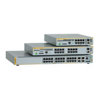
Allied Telesis AT-x230-18GT Installation Manual (102 pages)
Gigabit Ethernet Switches
Brand:
Allied Telesis
| Category:
Network Router
| Size: 6 MB
Table of Contents
Table of Contents
5
Preface
11
Symbol Conventions
12
Contacting Allied Telesis
13
Chapter 1: Overview
16
Features
16
Twisted Pair Ports
16
SFP Slots
16
Leds
17
Installation Options
17
Power Conservation
17
MAC Address Table
17
Package Contents for the AT-X230-10GT Switch
18
Figure 1: AT-X230-10GT Packaging
18
Package Contents for the AT-X230-10GP Switch
19
Figure 2: AT-X230-10GP Packaging
19
Package Contents for AT-X230-18GP and AT-X230-18GT Switches
20
Figure 3: AT-X230-18GP and AT-X230-18GT Packaging
20
Package Contents for the AT-X230-28GP Switch
21
Figure 4: AT-X230-28GP Packaging
21
Package Contents for the AT-X230-28GT Switch
22
Figure 5: AT-X230-28GT Packaging
22
Front and Back Panels on the AT-X230-10GT Switch
23
Figure 6: AT-X230-10GT Front Panel
23
Figure 7: AT-X230-10GT Back Panel
24
Front and Back Panels on the AT-X230-10GP Switch
25
Figure 8: AT-X230-10GP Front Panel
25
Figure 9: AT-X230-10GP Back Panel
26
Front and Back Panels on the AT-X230-18GP Switch
27
Figure 10: AT-X230-18GP Front Panel
27
Figure 11: AT-X230-18GP Back Panel
28
Front and Back Panels on the AT-X230-18GT Switch
29
Figure 12: AT-X230-18GT Front Panel
29
Figure 13: AT-X230-18GT Back Panel
30
Front and Back Panels on the AT-X230-28GP Switch
31
Figure 14: AT-X230-28GP Front Panel
31
Figure 15: AT-X230-28GP Back Panel
32
Front and Back Panels on the AT-X230-28GT Switch
33
Figure 16: AT-X230-28GT Front Panel
33
Figure 17: AT-X230-28GT Back Panel
34
Management Software
35
Twisted Pair Ports
36
Cable Requirements for Non-Poe Ports
36
Table 1. Twisted Pair Cable Requirements for the Non-Poe Ports
36
Power over Ethernet (Poe)
38
Poe Standards
38
Powered Device Classes
39
Cable Requirements
39
Table 2. IEEE Powered Device Classes
39
Table 3. Twisted Pair Cable Requirements for the 10BASE-T and 100BASE-TX Ports at 10 or 100Mbps
39
Power Budget
40
Table 4. Twisted Pair Cable Requirements for the 10/1000BASE-T and 100BASE-TX Ports at 1000Mbps
40
Port Prioritization
41
Wiring Implementation
42
Leds
43
POWER and FAULT Leds
43
Figure 18: POWER LED on an X230 Series Switch
43
Table 5. POWER LED Functional Descriptions
43
Figure 19: FAULT LED on an X230 Series Switch
44
Table 6. FAULT LED Functional Descriptions
44
10/1000BASE-T/100BASE-TX Link/Activity/Speed LED and Poe Status LED
45
Figure 20: Link/Activity/Speed and Poe Leds
45
Table 7. Link/Activity/Speed and Poe LED Descriptions
46
10/1000BASE-T/100BASE-TX Link/Activity/Speed LED and Duplex/Collision LED
47
Figure 21: Link/Activity/Speed and Duplex/Collision Leds
47
Table 8. Link/Activity/Speed and Duplex/Collision LED Descriptions
48
SFP Leds
49
Figure 22: SFP Link/Activity Leds on an X230 Series Switch
49
SD Card LED
50
Figure 23: SD Card Slot LED on an X230 Series Switch
50
Table 9. SFP Link/Activity LED Functional Descriptions
50
Table 10. SD Card LED Functional Descriptions
51
Ecofriendly Button
52
Figure 24: Ecofriendly Button on an X230 Series Switch
52
Power Supply
53
Fans
54
Chapter 2: Installation
56
Reviewing Safety Precautions
56
Selecting a Site for the Switch
58
Cable Specifications
59
Table 11. Twisted Pair Cabling and Distances
59
Unpacking the Switch: AT-X230-10GT
60
Unpacking the Switch: AT-X230-10GP
61
Unpacking the Switch: AT-X230-18GP and AT-X230-18GT
62
Unpacking the Switch: AT-X230-28GP
63
Unpacking the Switch: AT-X230-28GT
64
Installing the Switch on a Table or a Desktop
65
Figure 25: Attaching the Rubber Feet to a Switch
65
Removing the Feet from a Switch before Installing It in an Equipment Rack or on a Wall
66
Figure 26: Removing the Rubber Feet from a Switch
66
Installing an AT-X230-10GT Switch in an Equipment Rack
67
Figure 27: Fitting Handles to Rack Mount Brackets
67
Figure 28: Fitting Brackets to the Mounting
67
Figure 29: Attaching Cable Tray Brackets
68
Figure 30: Mounting an AT-X230-10GT Switch in the Brackets
68
Figure 31: Mounting an AT-X230-10GT Switch in the Rack
69
Figure 32: Securing Cables to the Cable Tray
69
Installing an AT-X230-10GP Switch in an Equipment Rack
70
Figure 33: Attaching Rack Mount Brackets to an AT-X230-10GP
70
Figure 34: Mounting an AT-X230-10GP Switch in an Equipment Rack
71
Installing an AT-X230-18GP, AT-X230-18GT, or AT-X230-28GT Switch in an Equipment Rack
72
Figure 35: Attaching Rack Mount Brackets to the AT-X230-18GP, AT-X230-18GT, or AT-X230-28GT Switch
72
Figure 36: Mounting an AT-X230-18GP, AT-X230-18GT, or
73
Installing an AT-X230-28GP Switch in an Equipment Rack
74
Figure 37: Attaching Rack Mount Brackets to the AT-X230-28GP Switch
74
Figure 38: Mounting an AT-X230-28GP Switch in an Equipment Rack
75
Installing an AT-X230-10GT Switch on a Wall
76
Figure 39: Ridges on the AT-BRKT-J23 that the Switch Rests on When Installed with the Front Panel Facing up
76
Figure 40: Securing the AT-X230-10GT Switch to the Wall with the Front Panel Facing up
77
Figure 41: Securing the AT-X230-10GT Switch to the Wall with the Front Panel Facing Right
77
Installing an X230-18GT, X230-28GT or X230-GP Series Switch on a Wall
78
Figure 42: Attaching Wall Mount Brackets to the Side of the Switch
78
Figure 43: Securing the Switch to the Wall
79
Cabling the Switch
80
Powering on the Switch
82
Figure 44: Lifting the AC Power Cable Hook on an X230 Series Switch
82
Figure 45: Plugging in the AC Power Cord on an X230 Series Switch
82
Starting a Local Management Session
84
Figure 46: Connecting the Management Cable to the Console Port of an X230 Series Switch
84
Monitoring the Initialization Processes
86
Figure 47: Switch Initialization Messages
86
Figure 48: Switch Initialization Messages (Continued)
87
Figure 49: Switch Initialization Messages (Continued)
88
Installing Optional SFP Transceivers
89
Figure 50: Removing the Dust Plug from an SFP Slot
89
Figure 51: Inserting an SFP Transceiver into an SFP Slot
90
Figure 52: Positioning the SFP Handle in the Upright Position
90
Figure 53: Ejecting an SFP Transceiver after Lowering the SFP Handle to the Downwards Position
91
Chapter 3: Troubleshooting
93
Physical Specifications
97
Dimensions
97
Weight
97
Table 12. Chassis Dimensions
97
Table 13. Chassis Weight
97
Environmental Specifications
98
Power Specifications
98
Table 14. Environmental Specifications
98
Table 15. Input Supply Voltage
98
Table 16. Power Specifications
98
Electrical Safety and Electromagnetic Certifications
99
Table 17. Safety and Electromagnetic Emissions Certifications
99
Connectors and Port Pinouts
100
Figure 54: RJ45 Connector and Port Pin Layout
100
Table 18. MDI Pin Signals (10BASE-T or 100BASE-TX)
100
Table 19. MDIX Pin Signals (10BASE-T or 100BASE-TX)
100
Table 20. RJ-45 1000BASE-T Connector Pinouts
101
Advertisement
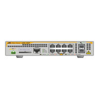
Allied Telesis AT-x230-18GT Installation Manual (80 pages)
Gigabit Ethernet Switches
Brand:
Allied Telesis
| Category:
Switch
| Size: 3 MB
Table of Contents
Installation Guide
1
Electrical Safety and Emissions Standards
3
Translated Safety Statements
4
Table of Contents
5
Preface
11
Symbol Conventions
12
Contacting Allied Telesis
13
Chapter 1: Overview
15
Features
16
Twisted Pair Ports
16
SFP Slots
16
Leds
17
Installation Options
17
Power Conservation
17
MAC Address Table
17
Package Contents for the AT-X230-10GP Switch
18
Figure 1: AT-X230-10GP Packaging
18
Package Contents for the AT-X230-18GP Switch
19
Figure 2: AT-X230-18GP Packaging
19
Front and Back Panels on the AT-X230-10GP Switch
20
Figure 3: AT-X230-10GP Front Panel
20
Figure 4: AT-X230-10GP Back Panel
21
Power Connector
21
Front and Back Panels on the AT-X230-18GP Switch
22
Figure 5: AT-X230-18GP Front Panel
22
Figure 6: AT-X230-18GP Back Panel
23
Management Software
24
Twisted Pair Ports
25
Power over Ethernet (Poe)
26
Poe Standards
26
Powered Device Classes
26
Cable Requirements
27
Table 1. IEEE Powered Device Classes
27
Table 2. Twisted Pair Cable Requirements for the 10BASE-T and 100BASE-TX Ports at 10 or 100Mbps
28
Power Budget
29
Table 3. Twisted Pair Cable Requirements for the 10/1000BASE-T and 100BASE-TX Ports at 1000Mbps
29
Port Prioritization
30
Wiring Implementation
31
Leds
32
POWER and FAULT Leds
32
Figure 7: POWER LED on an X230 Series Switch
32
Figure 8: FAULT LED on an X230 Series Switch
33
Table 4. AT-X230-10GP and AT-X230-18GP POWER LED Functional Descriptions
33
10/1000BASE-T/100BASE-TX Link/Activity/Speed LED and Poe Status LED
34
Table 5. AT-X230-10GP and AT-X230-18GP FAULT LED Functional Descriptions
34
Figure 9: AT-X230-10GP Link/Activity/Speed and Poe Leds
35
Figure 10: AT-X230-18GP Link/Activity/Speed and Poe Leds
35
Poe Status Led
35
Table 6. AT-X230-10GP and AT-X230-18GP Link/Activity/Speed and Poe LED Descriptions
36
SFP Leds
37
Figure 11: SFP Link/Activity Leds on an X230 Series Switch
37
SD Card LED
38
Figure 12: SD Card Slot LED on an X230 Series Switch
38
Table 7. SFP Link/Activity LED Functional Descriptions
38
Table 8. SD Card LED Functional Descriptions
39
Ecofriendly Button
40
Figure 13: Ecofriendly Button on an X230 Series Switch
40
Power Supply
41
Fans
42
Chapter 2: Installation
43
Reviewing Safety Precautions
44
Selecting a Site for the Switch
46
Cable Specifications
47
Table 9. Twisted Pair Cabling and Distances
47
Unpacking the Switch: AT-X230-10GP
48
Unpacking the Switch: AT-X230-18GP
49
Installing the Switch on a Table or a Desktop
50
Figure 14: Attaching the Rubber Feet to a Switch
51
Installing an AT-X230-10GP Switch in an Equipment Rack
52
Figure 15: Removing the Rubber Feet from a Switch
52
Figure 16: Attaching Rack Mount Brackets to an AT-X230-10GP
53
Figure 17: Mounting an AT-X230-10GP Switch in an Equipment Rack
54
Installing an AT-X230-18GP Switch in an Equipment Rack
55
Figure 18: Removing the Rubber Feet from a Switch
55
Figure 19: Attaching Rack Mount Brackets to the AT-X230-18GP Switch
56
Figure 20: Mounting an AT-X230-18GP Switch in an Equipment Rack
57
Installing the Switch on a Wall Using Brackets
58
Figure 21: Attaching the Wall Mount Brackets to the Side of the Switch
58
Figure 22: Securing the Switch to the Wall
59
Cabling the Switch
60
Powering on the Switch
62
Figure 23: Lifting the AC Power Cable Hook on an X230 Series Switch
62
Figure 24: Plugging in the AC Power Cord on an X230 Series Switch
62
Starting a Local Management Session
64
Figure 25: Connecting the Management Cable to the Console Port of an X230 Series Switch
64
Monitoring the Initialization Processes
66
Figure 26: Switch Initialization Messages
66
Figure 27: Switch Initialization Messages (Continued)
67
Figure 28: Switch Initialization Messages (Continued)
68
Installing Optional SFP Transceivers
69
Figure 29: Removing the Dust Plug from an SFP Slot
69
Figure 30: Inserting an SFP Transceiver into an SFP Slot
70
Figure 31: Positioning the SFP Handle in the Upright Position
70
Sfp Transceiver
70
Figure 32: Ejecting an SFP Transceiver after Lowering the SFP Handle to the Downwards Position
71
Chapter 3: Troubleshooting
73
Appendix A: Technical Specifications
77
Physical Specifications
77
Dimensions
77
Weight
77
Environmental Specifications
77
Table 10. Chassis Dimensions
77
Table 11. Chassis Weight
77
Table 12. Environmental Specifications
77
Power Specifications
78
Electrical Safety and Electromagnetic Certifications
78
Table 13. Chassis Weight
78
Table 14. Safety and Electromagnetic Emissions Certifications
78
Connectors and Port Pinouts
79
Figure 33: RJ45 Connector and Port Pin Layout
79
Table 15. MDI Pin Signals (10BASE-T or 100BASE-TX)
79
Table 16. MDIX Pin Signals (10BASE-T or 100BASE-TX)
79
Table 17. RJ-45 1000BASE-T Connector Pinouts
80
Advertisement
Related Products
Allied Telesis AT-x230-10GP
Allied Telesis AT-x230-18GP
Allied Telesis AT-x230-28GP
Allied Telesis AT-x230-28GT
Allied Telesis AT-x230L-17GT
Allied Telesis AT-x230L-26GT
Allied Telesis AT-x210-9GT
Allied Telesis AT-x210-16GT
Allied Telesis AT-x210-24GT
Allied Telesis AT-x210 Series
Allied Telesis Categories
Switch
Network Router
Media Converter
Network Hardware
Wireless Access Point
More Allied Telesis Manuals
Login
Sign In
OR
Sign in with Facebook
Sign in with Google
Upload manual
Upload from disk
Upload from URL