Allied Telesis AT-x230-10GP Installation Manual
Rack mount installation guide
Hide thumbs
Also See for AT-x230-10GP:
- User manual (1852 pages) ,
- Installation manual (86 pages) ,
- Installation manual (102 pages)
Advertisement
Quick Links
Advertisement

Related Manuals for Allied Telesis AT-x230-10GP


Summary of Contents for Allied Telesis AT-x230-10GP
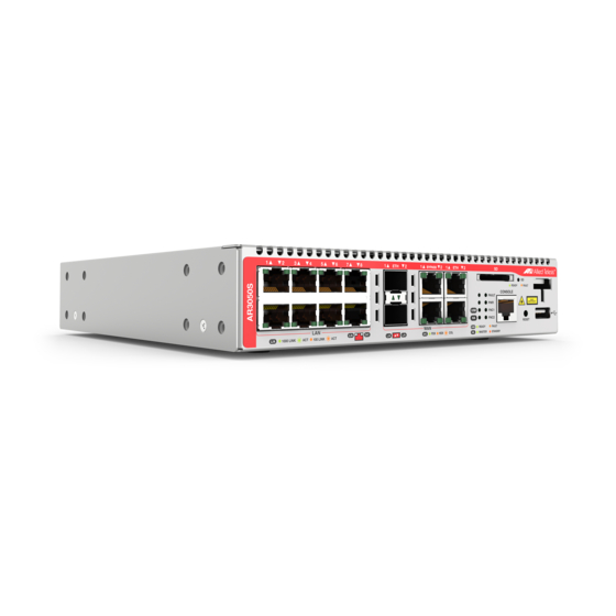
- Page 1 AT-x230-10GP AT-AR3050S AT-AR4050S -1 0 d re -2 32 W ER 10 00 10 /10 0 LIN X CU Rack Mount Installation Guide C613-04072-00 REV A...
- Page 2 Telesis, Inc. be liable for any incidental, special, indirect, or consequential damages whatsoever, including but not limited to lost profits, arising out of or related to this manual or the information contained herein, even if Allied Telesis, Inc. has been advised of, known, or should have known, the possibility of such damages.
- Page 3 AT-x230-10GP and AT-x230-18GP Rack Mount Installation Guide Contents Installation ................................. 7 Contents of AT-RKMT-J15 for the device ....................8 Installing a device in an equipment rack ...................... 9...
- Page 4 AT-x230-10GP and AT-x230-18GP Rack Mount Installation Guide...
-
Page 5: Table Of Contents
Figures Figure 1: Removing the rubber feet from the device ......................10 Figure 2: Installing the tray chassis in a 19-inch equipment rack ..................11 Figure 3: pulling out the tray ..............................11 Figure 4: Aligning the faceplate with the edge of the tray....................12 Figure 5: Aligning the faceplate 60mm off the edge of the tray ................... - Page 7 AT-x230-10GP, AT-AR3050S and AT-AR4050S Rack Mount Installation Guide Installation This chapter contains the following sections: “Contents of AT-RKMT-J15 for the device” on page 8 “Installing a device in an equipment rack” on page 9 The procedures apply to AT-x230-10GP, AT-AR3050S and AT-AR4050S.
- Page 8 The AT-RKMT-J15 rack mount kit can be purchased from your Allied Telesis dealer. The rack mount kit should contain the following items: 1 main unit (tray chassis) 4 M4x6mm truss head screws If any item is missing, contact your Allied Telesis dealer for assistance.
- Page 9 AT-x230-10GP, AT-AR3050S and AT-AR4050S Rack Mount Installation Guide Installing a device in an equipment rack Before installing Observe the following requirements before installing your device in an equipment rack: the device Verify that the rack is safely secured and will not tip over. Devices ...
-
Page 10: Figure 1: Removing The Rubber Feet From The Device
AT-x230-10GP, AT-AR3050S and AT-AR4050S Rack Mount Installation Guide How to install the You will need an AT-RKMT-J15 rack mount kit to install one or two side- by-side devices in a 19-inch equipment rack. The rack mount kit can be device purchased from your Allied Telesis dealer. -
Page 11: Figure 2: Installing The Tray Chassis In A 19-Inch Equipment Rack
AT-x230-10GP, AT-AR3050S and AT-AR4050S Rack Mount Installation Guide 2. I IGURE NSTALLING THE TRAY CHASSIS IN A INCH EQUIPMENT RACK 5. Pulling out the tray (Figure 3) To mount the device into the tray, you can loosen the tray fixing screws by screwing them on counterclockwise, and pull out the drawable tray to a maximum of 250mm from the tray chassis. -
Page 12: Figure 4: Aligning The Faceplate With The Edge Of The Tray
AT-x230-10GP, AT-AR3050S and AT-AR4050S Rack Mount Installation Guide 6. Aligning the devices You can secure the devices into the tray with the truss head screws through the holes on the slide-rail weld. You can use two truss head screws per device. You can align up to two devices side by side in the tray. -
Page 13: Figure 5: Aligning The Faceplate 60Mm Off The Edge Of The Tray
AT-x230-10GP, AT-AR3050S and AT-AR4050S Rack Mount Installation Guide 5. A IGURE LIGNING THE FACEPLATE MM BACK OFF THE EDGE OF THE TRAY 60mm 7. Returning the tray to its original place (Figure 6) After you have finished aligning the devices in the tray, slide the tray back to its original position, and tighten the tray fixing screws by screwing them on clockwise. - Page 14 AT-x230-10GP, AT-AR3050S and AT-AR4050S Rack Mount Installation Guide...
Need help?
Do you have a question about the AT-x230-10GP and is the answer not in the manual?
Questions and answers