Table of Contents
Advertisement
WARNING
To reduce the risk of fire, burn hazard or
other injury, read the Care and Use
Manual carefully and completely before
using your grill.
Example only: SERIAL #
Questions, problems, missing parts? Before returning to your retailer, call our
customer service department at 1-877-323-5263, 7 a.m.-6 p.m., PST, Monday-Friday, 8
a.m. – 12 p.m. Saturday.
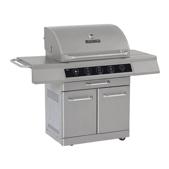
STAINLESS STEEL LP GAS GRILL
PRODUCT NAME/DESCRIPTION
PRODUCT NAME/DESCRIPTION
______________ MFG. DATE ______________ PURCHASE DATE: _________
ITEM / ARTICLE / ARTICULO # 272041
MODEL / MODELE / MODELO # 720-0533
WARNING
FOR OUTDOOR USE ONLY
WARNING
This grill is not intended to be
installed
in
or
on
vehicles and/or boats.
(page x)
(page x)
recreational
®
Advertisement
Table of Contents

Related Manuals for Perfect Flame 720-0533


Summary of Contents for Perfect Flame 720-0533
- Page 1 ITEM / ARTICLE / ARTICULO # 272041 STAINLESS STEEL LP GAS GRILL PRODUCT NAME/DESCRIPTION (page x) PRODUCT NAME/DESCRIPTION (page x) MODEL / MODELE / MODELO # 720-0533 WARNING WARNING FOR OUTDOOR USE ONLY To reduce the risk of fire, burn hazard or ®...
-
Page 2: Table Of Contents
TABLE OF CONTENTS Safety Information.…………………………………………………………………………...…..3-6 Assembly Instructions…………………………………………………………………………..…7-9 Installation Instruction………………….…………………. ……………………….…………….10-12 Operating Instructions…………………………………………………………………..…………13 Lighting Instructions…………………………………………………………………..…………..14-17 Touch Panel Flow Chart………………………………………………………………..…..……18-19 Special Remark For Touch Panel…………………………………………………..……………20 Light Operation Instructions……………………………………………………………………..21-22 Care And Maintenance…………………………………………………………………………..23-24 Trouble Shooting …………………………………………………………………………………24-28 Warranty…………………………………….…………………………………………..………….29 Replacement Parts List………………….…...………………………………………..…………30-32... -
Page 3: Safety Information
SAFETY INFORMATION Please read and understand this entire manual before attempting to assemble, operate or install the product. If you have any 7 a.m.-6 p.m., PST, Monday-Friday, 8 a.m. – 12 questions regarding the product please call customer service at 1-877-323-5263, p.m. - Page 4 WARNING WARNING If you smell gas: Do not store or use gasoline or other 1. Shut off gas to the appliance. flammable vapors and liquids in the 2. Extinguish any open flame. vicinity of this or any other appliance. 3. Open lid. 4.
- Page 5 TESTED IN ACCORDANCE WITH ANSI Z21.58b CALIFORNIA PROPOSITION 65-WARNING LATEST STANDARD 1.6b-2005 The burning of gas fuel generates some by- STANDARD FOR OUTDOOR COOKING GAS products, which are known by the State of California APPLIANCES. THIS GRILL IS FOR OUTDOOR to cause cancer or reproductive harm.
- Page 6 Do not use briquettes of any kind in the grill. The 720-0533 Liquid Propane grill is designed for optimum performance without the use of briquettes. Do not place briquettes on the flame tamers, as this will block the vent to the grill burners.
-
Page 7: Assembly Instruction
Assembly Instruction 1. Side Shelf Assembly Estimated Assembly Time: Approximately 10 minutes Required Tools: Phillips Screwdriver (not included) Open the grill lid and remove the side shelf from the fire box. The screws used to attach the side shelf are already screwed into the side of the grill cart. - Page 8 3. Side Burner Hose Quick Disconnect Assembly Estimated Assembly Time: Approximately 5 minutes Required Tools: Phillips Screwdriver Insert the side burner to the orifice and tighten it. Then insert the igniter wire the hole on below side burner igniter. WARNING 1.
- Page 9 5. Liquid Propane Cylinder Retention System Attach the liquid propane gas cylinder to the hole on bottom panel. Make sure tank is leveled with bottom panel for proper vapor withdraw. 6. Propane Regulator Hook-Up Attach the regulator to the propane cylinder by turning the regulator handle clockwise.
-
Page 10: Installation Instruction
This grill is configured for Liquid Propane. Do not use a Natural Gas supply. Total gas consumption (per hour) of the 720-0533 Liquid Propane gas grill with all burners set on “HI”: Main burners 52,000 BTU/Hr. - Page 11 The Liquid Propane cylinder must be fitted with an Overfill Protection Device (OPD). Remove the plastic valve cover from the Liquid Propane cylinder. Make sure the grill gas hoses do not contact the grease pan or grill firebox when the Liquid Propane cylinder is placed into the cart. CONNECTING THE LIQUID PROPANE CYLINDER Your grill is equipped with gas supply orifices for use only with Liquid Propane gas.
- Page 12 TO TEST Press the burner valves “OFF”. Turn the Liquid Propane cylinder valve counterclockwise to open the valve. Apply the soap solution to all gas fittings. Soap bubbles will appear where a leak is present. If a leak is present, immediately turn the gas supply “OFF” and tighten leaky fittings. Turn the gas back “ON”...
-
Page 13: Operating Instructions
OPERATING INSTRUCTIONS General Use of the Grill Each main burner is rated at 13,000 BTU/Hr. The main grill burners encompass the entire cooking area and are side ported to minimize blockage from falling grease and debris. Above the burners are flame tamers. The igniter knobs are located on the lower center portion of the valve panel. -
Page 14: Lighting Instructions
Lighting Instruction SIDE BURNER Control Button MAIN BURNER (1-2) (“S” Button, Electrical Control Button HI Button, and ON/OFF Button (Activation Button, LO Button) HI Button, and LO Button) TIMER Control Button (Activation Button, “+” REAR BURNER “R” Button, and “-” Button) MAIN BURNER (3-4) Button Control Button... - Page 15 To Light Main Burners (1-2) “HI” Button Flame- Indication Activation Button (Symbol Light is different from the one for MAIN BURNERS 3-4) “LO” Button • Activation Button (MAIN BURNERS 1-2) controls the 2 main burners at the left side of the firebox. The main burner 1 and 2 can be turned on by pressing the Activation Button for 3 seconds;...
- Page 16 To Light Side Burner “HI” Button Flame- Indication Light “S” Button “LO” Button • The side burner can be turned on by pressing the “S” Button (activation button for side burner) for 3 seconds; the valve of the corresponding burner will be opened, and the igniter will start to ignite until the burner catches fire. •...
- Page 17 To Operation Timer LCD Display (shows Time and Error Codes) “-” Button “+” Button Timer Activation Button • The timer is function to control the main-burners and rear burner. It does not control the side burner. When the timer is set, the main-burners and the rear burner can remain turned on until the preset time is over. •...
-
Page 18: Touch Panel Flow Chart
Touch panel Flow Chart Start Switch ON the mechanical ON/OFF Switch Self Inspection No (1 Buzz) Yes (3 Buzzes) Any error? System can be System can not be operated. operated. (Proceed Error code is shown on the LCD to Attachment 2) display, and corresponding flame-indication lights will flash (See Attachment 1). - Page 19 Attachment 2: Press Electrical ON/OFF Button for 3 seconds When the system is OFF When the system is ON System turned ON. Main Power System turned OFF. All LED LED Light is on. lights are off. System is automatically Is any burner turned on turned off.
-
Page 20: Special Remark For Touch Panel
Special Remark For Touch Panel Switch the main power ON (by pressing the mechanical on/off switch) before using. Switch the main power OFF when not in use. The control system will perform a self-inspection after the main power is switch ON. The flame- indication lights will flash when the corresponding burner is being checked. -
Page 21: Light Operation Instructions
Light Operation Instructions 1.Make sure the light power switch under the control panel is in the “OFF” position 2.Connect power plug to properly grounded outlet. 3.Turn the light power switch to “ON”. WARNING Keep any electrical supply cord away from any heated surface. Halogen Bulb Replacement Make sure that the grill has cooled before changing the light bulb. - Page 22 6. To re-install the light, replace the glass cover, insert the light bulb housing into the grill and insert and tighten the screw. Cleaning Method Follow steps 1 thru 4 above for glass cover removal. Use a damp towel to clean the surface of the glass Cover.
-
Page 23: Care And Maintenance
CARE AND MAINTENANCE Stainless Steel There are many stainless steel cleaners available. Always use the mildest cleaning process first, scrubbing in the direction of the grain. Do not use steel wool as it will scratch the surface. To touch up noticeable scratches in the stainless steel, sand very lightly with dry 100 grit sand paper in the direction of the grain. -
Page 24: Troubleshooting
CAUTION Keep outdoor cooking gas appliance area clear and free from combustible materials, gasoline and other flammable vapors and liquids. Do not obstruct the flow of combustible and ventilation air. 3. Keep the ventilation opening(s) of the enclosure free and clear from debris. Flame Characteristics Check for proper burner flame characteristics. - Page 25 BEFORE CALLING FOR SERVICE If the grill does not function properly, use the following checklist before contacting your dealer for service. You may save yourself the cost of a service call. Testing Item Specification Current -- Not in Operation Test by Ammeter Current -- During Ignition Test by Ammeter Current -- In Operation...
- Page 26 Press Activation Button (MAIN BURNERS 1-2) and Operation of the Burners hold for 3 seconds to turn ON/OFF the burners. Press “HI” and “LO” Button (MAIN BURNERS 1-2) to adjust the flame. The Flame-Indication Lights will show Adjusting the Flame the level of the flame.
- Page 27 Press "S" Button and hold for 3 seconds to turn Operation of the Burner ON/OFF the burner. Press “HI” and “LO” Button (SIDE BURNER) to adjust the flame. The Flame-Indication Lights will show the Adjusting the Flame level of the flame. One beep will sound every time the flame is adjusted.
- Page 28 Press Timer Activation Button and hold for 3 seconds to turn ON/OFF the burner. 1 beep will sound when the timer is turning on, and 3 beeps will sound when turning Operation of the Timer off. The timer can only be activated when either the main burners or the rear burner is in use.
-
Page 29: Warranty
WARRANTY Nexgrill Industries, Inc. warrants to the original consumer-purchaser of each Perfect Flame Outdoor Gas Grill that when subject to normal residential use, it is free from defects in workmanship and materials for the periods specified below. This warranty excludes grills used in rental or commercial applications. - Page 30 For replacement parts, call our customer service department at 1-877-323-5263, 7 a.m. – 6 p.m., PST, Monday – Friday and 8 a.m. – 12 p.m. PST, Saturday. REF# DESCRIPTION REF# DESCRIPTION Temperature Gauge Lighting Rod Cover Main lid screw Lighting Rod Main lid Screw Cover Rubber grommet, door handle Main Lid...
- Page 31 REF# DESCRIPTION REF# DESCRIPTION Side Burner Bowl Assembly Frame Rotisserie Igniter Wire Side burner igniter wire Rotisserie Burner Side burner fix bracket A Rear Baffle Side pipe burner Main Burner Igniter Wire A Side burner fix bracket B Main Burner Igniter Wire B Side burner orifice size Main Burner Igniter Wire C Side burner gas flex line...
- Page 32 EXPLODED VIEW MODEL 720-0533...
Need help?
Do you have a question about the 720-0533 and is the answer not in the manual?
Questions and answers