Advertisement
Table of Contents
- 1 Table of Contents
- 2 Safety Information
- 3 Package Contents List
- 4 Hardware Contents / Preparation
- 5 Assembly Instructions
- 6 In Place and Tighten the Screws
- 7 Installation Instructions
- 8 Operating Instructions
- 9 Care and Maintenance
- 10 Troubleshooting
- 11 Warranty
- 12 Replacement Parts List
- Download this manual
See also:
User Manual
WARNING
To reduce the risk of fire, burn hazard or
other injury, read the Care and Use
Manual carefully and completely before
using your grill.
SERIAL # ______________ MFG. DATE ______________ PURCHASE DATE: _________
Questions, problems, missing parts? Before returning to your retailer, call our customer service
department at 1-877-323-5263, 7 a.m.-6 p.m., PST, Monday-Friday, 8 a.m.-12 p.m. Saturday.
PDF 文件使用 "pdfFactory Pro" 试用版本创建
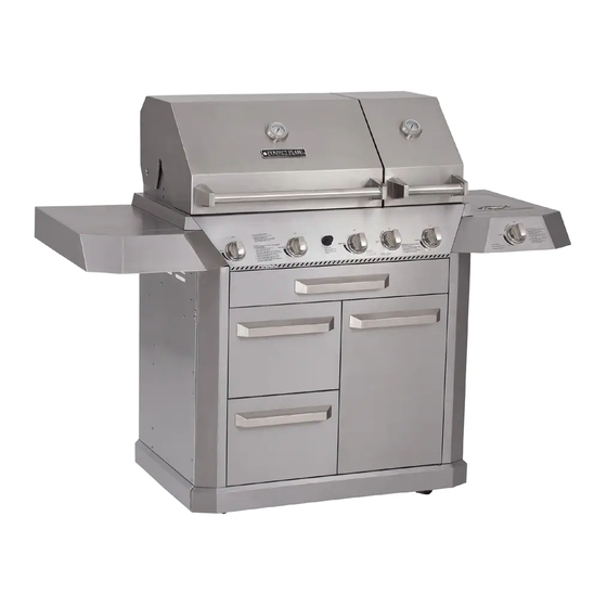
STAINLESS STEEL LP GAS GRILL
PARRILLA A GAS PL DE ACERO
MODEL / MODELE / MODELO # 720-0335
WARNING
FOR OUTDOOR USE ONLY
WARNING
This grill is not intended to be
installed in or on recreational
vehicles and/or boats.
www.fineprint.cn
ITEM / ARTICLE / ARTICULO #242608
(página 32)
®
Advertisement
Table of Contents

Related Manuals for Perfect Flame 720-0335


Summary of Contents for Perfect Flame 720-0335
- Page 1 ITEM / ARTICLE / ARTICULO #242608 STAINLESS STEEL LP GAS GRILL PARRILLA A GAS PL DE ACERO (página 32) MODEL / MODELE / MODELO # 720-0335 WARNING WARNING To reduce the risk of fire, burn hazard or FOR OUTDOOR USE ONLY ®...
-
Page 2: Table Of Contents
TABLE OF CONTENTS Safety Information.…………………………………………………………………………...……..…3 Package Contents List…………………………………………………………………………..…….7 Hardware Contents / Preparation………………….…..…………….…………….……………….9 Assembly Instructions…………………………………………………………………..…………..…9 Installation Instructions..………………………………………………………………..……………17 Operating Instructions.………………………………………………………………..…..………..20 Care and Maintenance………………………………………………………………..…………..…25 Troubleshooting……………………………………………………………………..………………..27 Warranty…………………………………….…………………………………………..……….……28 Replacement Parts List………………….…...………………………………………..…………….29 PDF 文件使用 "pdfFactory Pro" 试用版本创建 www.fineprint.cn... -
Page 3: Safety Information
SAFETY INFORMATION Please read and understand this entire manual before attempting to assemble, operate or install the product. If you have any questions regarding the product please call customer service at 1-877-323-5263, 7 a.m.-6 p.m., PST, Monday-Friday, 8 a.m.-12 p.m. on Saturday . 1. - Page 4 CAUTION 1. The grill head is heavy and will require two or more people to lift and position onto grill cart. 2. Before cleaning, make sure the gas supply and control knobs are in the “OFF” position and the burners have cooled.
- Page 5 SAFETY PRACTICES TO AVOID INJURY When properly cared for, your grill will provide safe, reliable service for many years. However, extreme care must be used as the grill produces intense heat that can increase accident potential. When using this appliance basic safety practices must be followed, including the following: Do not repair or replace any part of the grill unless specifically recommended in this manual.
- Page 6 If the unit is stored indoors, make sure it is cool. Do not use briquettes of any kind in the grill. The 720-0335 liquid propane gas grill is designed for optimum performance without the use of briquettes. Do not place briquettes on the flame tamers, as this will block the vent to the grill burners.
- Page 7 PLACEMENT OF THE GRILL CLEARANCE Non-Combustible Construction A minimum of 24 inches clearance from the back of the grill to non-combustible materials are required for the lid to open fully. Outdoor cooking appliance shall not be used under overhead combustible construction. WARNING Do not install this unit into combustible enclosures.
-
Page 8: Package Contents List
PACKAGE CONTENTS LIST 1. Body Assembly-----------1pc 2. Bottom Panel-----------1pc 3. Upper Drawer Slide Bracket-- 4. Left Side Panel-----------1pc 5. Right Side Panel-------1pc 6. Center Panel---------1pc 7. Back Panel---------------1pc 8. Drawer Heat Shield---1pc 9. Cart Frame--------------1pc 10. Drawer-------------------2 pcs 11. Door--------------------1pc 12. -
Page 9: Hardware Contents / Preparation
HARDWARE CONTENTS Pack Description Quantity 5/32" x 10 MM Truss Head Screw 37 pcs. 5/32" Locking Washer 29 pcs. 1/4" x 15 MM Truss Head Screw 16 pcs. 1/4" Locking Washer 36 pcs. 1/4" x 10 MM Truss Head Screw 16 pcs. -
Page 10: In Place And Tighten The Screws
Fig. 2 2. Drawer Upper Slide Bracket Assembly Remove the drawer slide bracket (2-1) from the carton. (2-2) Attach the drawer slide bracket (2-1) to the left side panel (2-2) with 4 – 5/32" x 10mm truss head screws from pack A and 4 –... - Page 11 Fig. 5 4. Center Panel Assembly Remove the cart center panel (5-1) from the carton. (5-1) Attach the cart center panel (5-1) to the bottom panel (5- 2) with 2 – 5/32" x 10mm truss head bolts from pack A and 2 –...
- Page 12 Fig. 8 6. Drawer Heat Shield Assembly Remove the drawer heat shield from the carton (8-1). Attach (8-1) the drawer shield (8-1) to the cart center panel (8-2) using 3 – 5/32" x 10mm truss head screws from pack A and 3 –...
- Page 13 Fig. 12 9. Door Assembly Place hinge pin that is on the front trim panel (12-1) into the (12-3) hole located on the bottom of the door (12-2). Line the top of the door with the hinge bracket (12-3) and insert the 5/32" (12-1) x 10mm ladder bolt from pack H.
- Page 14 Fig. 16 12. Side Shelf Front Panel Assembly (16-2) Attach the side shelf front panel (16-1) to the side shelf (16- 2) with 4 – 5/32" x10mm truss head screws from pack A as shown in fig. 16. (16-1) Fig. 17 13.
- Page 15 Fig. 20 Re-install screws & washers removed from fig.18 to secure the left side shelf (20-1) and right side burner (20-2) onto the main control panel. (20-1) (20-2) Fig. 21 15. Electronic Igniter & Battery Installation Remove the ignition button housing and the rubber gasket (21- 1) from the left side shelf front panel (21-2) as shown in fig.
- Page 16 Fig. 24 Connect the side burner igniter wire (24-1) to the side (24-4) burner gas valve (24-2). Turn the control knob (24-3) and look for a spark under the side burner cooking grid (24-4) (24-1) to make sure the connection is good. (24-2) (24-3) Fig.
-
Page 17: Installation Instructions
Only the pressure regulator and hose assembly supplied with the grill should be used. Any replacement pressure regulator and hose assembly must be specified by the grill manufacturer. Total gas consumption (per hour) of the 720-0335 liquid propane gas grill with all burners set on “HI”: Main burners 42,000 BTU/Hr. - Page 18 7. Before lighting the grill, use a soap and water solution to check all the connections for leaks. 8. If a leak is found, turn the cylinder valve off and do not use the grill until a local liquid propane dealer can make repairs.
- Page 19 GAS FLOW CHECK Each grill burner is tested and adjusted at the factory prior to shipment. However, variations in the local gas supply may make it necessary to adjust the burners. Flames should be blue and stable with no yellow tips, excessive noise or lifting (see “Flame Characteristics”...
-
Page 20: Operating Instructions
OPERATING INSTRUCTIONS General Use of the Grill and Rotisserie Each main burner is rated at 14,000 BTU/Hr. The main grill burners encompass the entire cooking area and are side ported to minimize blockage from falling grease and debris. Above the burners are stainless steel flame tamers. - Page 21 3. Slide the first meat fork onto the skewer rod prongs toward the food. 4. Center the product to be cooked on the skewer, and then push the meat forks firmly together. 5. Tighten the wing nuts. 6. It may also be necessary to wrap the food with butcher’s string to secure loose portions. Never use nylon or plastic string to wrap the food.
- Page 22 Yellow flames indicate insufficient air. Noisy flames or flames that lift away from the burner indicate too much air (See “Flame Characteristics” illustration on page 26). TO LIGHT THE ROTISSERIE BURNER: 1. Open the lid, push and turn rotisserie burner knob slowly to “IGNITE/ON”, hold in until the burner ignites.
- Page 23 Rotisserie Burner Lighting 1. Push and turn the rotisserie burner control knob slowly to the “IGNITE/ON” setting, hold in until the burner ignites. Continue to press and hold for 15 seconds (if the burner does not ignite, follow the match lighting instructions on page 24). Sear Burner Lighting 1.
- Page 24 To Match Light the Grill If the burner will not light after several attempts using the control knobs, the burner may be lit with a match. WARNING CAUTION When lighting, keep your face and hands as far When using a match to light the grill make sure to away from the grill as possible.
-
Page 25: Care And Maintenance
Using the Side Burner Inspect the gas supply hose prior to turning on the gas. If there is evidence of cuts, wear or abrasion, it must be replaced prior to use. Do not use the side burner if gas odor is present. Note Keep a spray bottle of soapy water near the grill and check the gas connections before each use. - Page 26 Grill Burners Extreme care should be taken when moving a burner. It must be correctly centered on the orifice before any attempt is made to relight the grill. Frequency of cleaning will depend on how often you use the grill. Failure to properly place the burner over the orifice could cause a fire to occur behind and beneath the valve panel, thereby damaging the grill and making it unsafe to operate.
-
Page 27: Troubleshooting
TROUBLESHOOTING WARNING Spiders and insects can nest inside the burners of the grill and disrupt gas flow. This very dangerous condition could cause a fire behind the valve panel, thereby damaging the grill and making it unsafe for operation. Inspect the grill at least twice a year. When to Look for Spiders You should inspect the burners at least twice a year or immediately after any of the following conditions occur:... -
Page 28: Warranty
WARRANTY Nexgrill Industries, Inc. warrants to the original consumer-purchaser of each Perfect Flame Outdoor Gas Grill that when subject to normal residential use, it is free from defects in workmanship and materials for the periods specified below. This warranty excludes grills used in rental or commercial applications. -
Page 29: Replacement Parts List
REPLACEMENT PARTS LIST I15Y06P-1 For replacement parts, call our customer service department at 1-877-323-5263, 7 a.m. – 6 p.m., PST, Monday – Friday and 8 a.m. – 12 p.m. PST, Saturday. REF# DESCRIPTION REF# DESCRIPTION Temperature Gauge Top Side Panel W/Bracket, Left Side Lid Side Panel, Left Main Lid... - Page 30 REF# DESCRIPTION REF# DESCRIPTION Thermocouple (sear burner) Side Burner Bracket Side Burner Orifice Brass Sear Burner Connector Sear Burner Orifice Side Burner Flex Gas Sear Burner Igniter Wire Side Burner Control Panel Sear Burner Bowl Assembly Side Gas Valve Side Shelf Trim Panel, Right Side Manifold Side Burner Lid Handle Back Panel, Top...
- Page 31 Printed in China PDF 文件使用 "pdfFactory Pro" 试用版本创建 www.fineprint.cn...
Need help?
Do you have a question about the 720-0335 and is the answer not in the manual?
Questions and answers