
Related Manuals for JAI TM-1327GE Series


Summary of Contents for JAI TM-1327GE Series
- Page 1 TM/RM-1327GE Series Digital Monochrome/Color Progressive Scan, Interline-Transfer Gigabit Ethernet Camera Document Version: E Document P/N: 10164...
- Page 3 The material contained in this manual consists of information that is proprietary to JAI, Inc., and may only be used by the purchasers of the product. JAI, Inc. makes no warranty for the use of its product and assumes no responsibility for any errors which may appear or for damages resulting from the use of the information contained herein.
- Page 4 WARNING Changes or modifications to this unit not expressly approved by the party responsible for FCC compliance could void the user’s authority to operate the equipment. TM-1327GE Series Operation Manual JAI, Inc. 625 River Oaks Parkway San Jose, CA 95134...
- Page 5 TM/ RM -1327GE Series February 12, 2008 Notice...
- Page 6 TM/ RM-1327GE Series Table of Contents Disclaimer Notice....................iii Table of Contents ....................v List of Figures ....................... vii List of Tables......................ix Table of Contents...
- Page 7 TM/ RM -1327GE Series List of Figures List of Figures...
- Page 8 TM/ RM-1327GE Series viii List of Figures...
- Page 9 TM/ RM -1327GE Series List of Tables List of Tables...
- Page 10 TM/ RM-1327GE Series List of Tables...
-
Page 11: Software Introduction
Software Introduction 1.1 Scope of the Document This manual describes how to access and use features specific to JAI's Gigabit Ethernet camera, the TM-1327GE. The camera’s different operation modes are described in the hardware section of this manual, which begins on page 29. -
Page 12: Software Installation
To install the JAI GigE camera-control software, read and follow the directions included in the document download card. If your computer does not have Internet access, call JAI at 1 800 445 5444 to request that the software be sent to you on a CD-ROM. - Page 13 >”Documentation”-->” Cam2Net IP Device Drivers”. An Acrobat file has instruction to help guide you through the proper install. 10. Go to “Start” --> “Programs” --> “JAI AS” --> “Cam2Net” --> “Launch Coyote application” to launch the camera control tool. 1.4.3...
- Page 14 TM/ RM-1327GE Series Advanced Configuration Window, select the “Pixel Type” tab. Make sure the camera is set to the proper color space and pixel depth, then click the check-box labeled “Use 3 x 3 Bayer Interpolation” in the “Conversion Options” panel. More information on color interpolation and the color filter array (CFA) can be found in Section 8.2 beginning on page 38 of this manual.
- Page 15 TM/ RM -1327GE Series Connectors The camera has two sockets, as shown in Figure 6 below: • 12-pin Hirose for power, trigger, RS-232 communication and TTL I/O. • RJ-45 for Gigabit Ethernet. Figure 6. TM-1327GE Back Panel Connectors These connectors are described in Section 2.1 and Section 2.2 below. 2.1 Power and Signals Connector The GE camera receives power and signal through a 12-pin Hirose connector.
- Page 16 PC, you must use a cross-over cable. Refer to the Cam2Net User's Manual for details. Figure 8. Ethernet GigE Socket GigE JAI recommends the use of shielded cables to reduce emissions and for CE/FCC compliance. Double-shielded cables will further reduce emissions. Connectors...
-
Page 17: Configuring The Camera
TM/ RM -1327GE Series Configuring the TM-1327GE Camera The configuration of your GigE camera consists of two parts: • The imager configuration (CCD and control circuits) • The internal frame grabber configuration The imager can be configured for partial scan, binning, etc., just like a Camera Link camera. The internal frame grabber is automatically configured for the pixel type, windowing, image size and I/O and so on, by the GigE camera software. - Page 18 TM/ RM-1327GE Series Figure 11. Integrated GigE Camera Software [screen shot] 3.2.1 GUI Features You can control the following camera functions using the integrated camera software: • Shutter Speed and Mode • Scan Mode • Gain Control • Offset Level •...
- Page 19 TM/ RM -1327GE Series Figure 14. Mode Control Pull-down [screen shot] Shutter Speed The shutter speed setting, shown in Figure 15, allows you to select the specific shutter speed for Manual shutter and Async shutter. Manual shutter speed 0 is No Shutter mode; Async shutter speed 0 is Async - No Shutter mode;...
- Page 20 TM/ RM-1327GE Series The built-in auto black level control adds tiny positive or negative voltages to both Vtop and Vbottom to compensate black level changes due to temperature. Auto black level does not change the overall system gain. Figure 18. Offset Level [screen shot] 3.4.6 Look-Up Table...
- Page 21 1. Page 0 is password-protected and you cannot write to it. If you find that you do need to write to page 0, contact JAI for password access. Note: Configurations such as grabber settings, pulse generator, GPIO, and image setting must be saved into the XML file.
- Page 22 TM/ RM-1327GE Series 3. Click “Configure” and select the RGB filter tab from the Advanced Configuration window. Show the camera a piece of white paper to make sure that the image is not saturated. 4. Click Analyze to automatically calculate the white balance. 5.
- Page 23 TM/ RM -1327GE Series Signal Handling This section describes the signal handling of the GE cameras in the following section: • “Camera Inputs” on page 18 • “GPIO Control Block” on page 19 • “GPIO Label Tables” on page 21 •...
- Page 24 TM/ RM-1327GE Series Inputs I0 through I7 can be either external or internal inputs to the look-up table. The outputs are used by the imager part of the GE camera. The HD and VD signals can be passed through, bypassing the GPIO lookup table. Figure 24 on page 20 shows a screen dump of the GPIO configuration page, where HD/VD bypass selection can be made.
- Page 25 TM/ RM -1327GE Series Table 3 shows which output labels carry the output signals. Table 3 GPIO Look-Up Table Output Labels Output label Signal Description TTL-OUT(STROBE) Strobe output EVINIT Trigger EXT_VD Vertical Drive EXT_HD Horizontal Drive pulse_trig1 Pulse Generator 1 gets its trigger here pulse_trig0 Pulse Generator 0 gets its trigger here pulse_trig3...
- Page 26 TM/ RM-1327GE Series GigE Series Camera Serial Commands You can control the GigE series cameras by serial command either using RS-232 or Camera Link. The Start character is always “:” and the End character is always <CR> (return). For example, to set Asynchronous Pulse Width Mode, send the command :ASH=9<CR>...
- Page 27 TM/ RM -1327GE Series Table 5 18 Bytes Status Report Byte 1, 2 Gain Control (H’0000 - H’00FF) Byte 3, 4 VTOP VTOP (H’0080 - H’00C0) Byte 5, 6 VBTM VBOTTOM (H’0078 - H’00FF) Byte 7,8 Reserved Byte 9 Function Flag 0 Bit 7 output pixel order 1 “00”=<-- “10”=<-- “01”=<--...
- Page 28 TM/ RM-1327GE Series Byte 16 (X2, Y2 = H’00 - H’FF) Byte 17 User Scan Start Point of User Scan Area Active Line of Byte 18 Active Line of User Scan Area Scan Byte 19 Direct Shutter H’000 - H’40F Byte 20 Byte 21, 22 Byte 23, 24 Reserved...
-
Page 29: Hardware Introduction
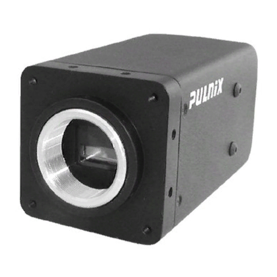
“Features” on page 30 6.1 Product Description The JAI TM-1327GE is a high-speed progressive scan CCD camera. The interline-type CCD permits full vertical and horizontal resolution of very high speed shutter images and applications. The electronic shutter, which has speeds to 1/16,000 second, can be reset asynchronously by external pulse control. - Page 30 TM/ RM-1327GE Series − High sensitivity and low noise at fast scanning. The CCD has an excellent S/N ratio at the default setting greater than 51dB. • Electronic shutter The TM-1327GE has a substrate drain-type shutter mechanism which provides superb pictures at various speeds without smearing.
-
Page 31: Getting Started
TM/ RM -1327GE Series Installation The following instructions will help you to set up your camera quickly and easily. JAI suggests that you read through these instructions first, before you unpack and set up your camera system. 7.1 Getting Started 7.1.1... - Page 32 Figure 27. GigE Ethernet Connector Use at least cat5e UTP cables (cat6 cables are preferred). Refer to the Cam2Net User’s Manual for details. JAI recommends the use of shielded cables to reduce emissions and for CE/FCC compliance. Double-shielded cables further reduce emissions.
- Page 33 Make sure all connections are properly insulated to prevent shorting. JAI Power Cables If you are using JAI power cables, such as the 12P-02S, refer to the Figure 26 which shows the cable pin-out diagram and pinouts. The color-coded leads use Gray for Ground and Yellow for +12V.
- Page 34 TM/ RM-1327GE Series 7.2.4 Attaching the Camera Lens The TM-1327GE camera accepts 2/3” or larger format size C-mount lenses. To attach the C-mount lens1 to the camera, carefully engage the threads and rotate the lens clockwise until it firmly seats on the mounting ring.
-
Page 35: Table Of Contents
On-chip micro lenses mean increased sensitivity. 8.2.1 Color Filter Array JAI AccuPiXEL cameras use Bayer CFA (color filter array) as their standard primary color filter. This filter provides the most popular color interpolation supported by numerous software suppliers. Hardware Operation... -
Page 36: Operation
R/G start or G/R start, as well as G/B start and B/G start. Once the correct scanning is configured, the rest of the interpolation will be exactly the same. Please contact JAI for further information regarding CCD manufacturers. - Page 37 TM/ RM -1327GE Series Figure 30. Example of Color CCD CFA Pattern 8.2.4 Sync and Data The individual color data is exactly the same as the pixel data. This means that the timing relationships of the color cameras are also the same as of the B/W cameras. For a detailed timing chart, please refer to each B/W camera’s data sheet and manual.
-
Page 38: Interpolation Software
When LUT is selected, black-level adjustment must be more accurate than for B/W cameras. For a detailed timing chart, please refer to the standard AccuPiXEL camera data sheet, or contact JAI. 8.2.6 Interpolation Software The color interpolation can be performed in the frame grabber or by using the host computer’s CPU. -
Page 39: Electronic Shutter
3 x 3 interpolation, 2 x 2 interpolation, color matrix, white balance capability, etc. All AccuPiXEL color cameras are carefully designed for maximum color performance. JAI strongly suggests that you use digital output for the best performance. - Page 40 TM/ RM-1327GE Series 8.5.2 Internal Direct Shutter Speed Control Figure 33. Internal Direct Shutter Speed Control The video signal starts with internal VINIT. When the external VINIT pulse is applied, internal VINIT is latched to HD and the internal VINIT is delayed to set up the shutter speed period. The shutter speed is controlled by communication software.
-
Page 41: Programmable Look-Up Table (Lut) And Knee Control
TM/ RM -1327GE Series Figure 34. No-Delay Shutter 8.5.4 Async Direct Shutter Async Direct Shutter exposure is determined by a direct shutter value entered from 1 to 1040. The shutter value equals 1.5H (horizontal line time) or 47.6 μsec. for each increment. The Async Direct Shutter exposure timing functions exactly the same as the internal shutter speed control. -
Page 42: Camera Timing Charts
TM/ RM-1327GE Series 8.7 Camera Timing Charts Hardware Operation... - Page 43 TM/ RM -1327GE Series Hardware Operation...
-
Page 44: Video Output
TM/ RM-1327GE Series 8.8 Video Output Table 7 Video Output (Horizontal Timing) Horizontal Timing Number of pixels 30fps (μs) 1741 31.65 6.35 1392 25.31 1.11 1.11 4.44 Table 8 Video Output (Vertical Timing) Vertical Timing Full Scan Area User Scan Area (SP:x, TL:y) Number of lines 30fps (μs) Number of lines... - Page 45 TM/ RM -1327GE Series Table 10 External HD Locking and External VD Reset (Vertical Timing) Vertical Timing Full Scan Area User Scan Area (SP:x, TL:y) Number of lines 30fps (μs) Number of lines 30fps (μs) <1 <31.65 <1 <31.65 284.89 284.89 1044 33047.34...
-
Page 46: Troubleshooting
9.1 Problems and Solutions This section contains troubleshooting tips for common problems. Generally, problems can easily be solved by following these instructions. If the following remedies fail to offer a solution to your problems, contact a JAI representative. 9.1.1 Symptom: No Video Remedies: Check that the following are properly connected and operational. -
Page 47: Specifications
TM/ RM -1327GE Series 10 Appendix 10.1 Specifications Table 13 TM-1327GE Camera Specifications Table Feature TM-1327GE Imager 2/3” progressive scan interline transfer CCD Active Area 8.98mm x 6.71mm Active Pixels 1392 (H) x 1040 (V) Cell Size 6.45?m x 6.45?m Display Mode 1392 (H) x 1040 (V) @ 30 Hz (Active Pixels) - Page 48 TM/ RM-1327GE Series 10.1.1 TM-1327GE Physical Dimensions Figure 36. Physical Dimensions Specifications...
- Page 49 TM/ RM -1327GE Series 10.1.2 Spectral Response Figure 37. Spectral Response Specifications...
- Page 51 TM/ RM -1327GE Series...
- Page 52 Europe, Middle East & Africa Phone +45 4457 8888 Fax +45 4491 8880 Asia Pacific Phone +81 45 440 0154 Fax +81 45 440 0166 Americas Phone (Toll-Free) 1 800 445-5444 Phone +1 408 383-0301 www.jai.com...
Need help?
Do you have a question about the TM-1327GE Series and is the answer not in the manual?
Questions and answers