Mitsubishi Electric G-50A Technical Manual
Air conditioning network system centralized controller g-50a and integrated centralized control software tg-2000a
Hide thumbs
Also See for G-50A:
- Instruction book (48 pages) ,
- Operation manual (31 pages) ,
- Installation manual (12 pages)

Related Manuals for Mitsubishi Electric G-50A


Summary of Contents for Mitsubishi Electric G-50A
- Page 1 Mitsubishi Electric Air Conditioning Network System Centralized Controller G-50A and Integrated Centralized Control Software TG-2000A Technical Manual...
-
Page 3: Table Of Contents
2.4.1 Centralized controller : G-50A ........ - Page 4 13.2.1 Setting method for connecting G-50A to exclusive LAN ....... .
-
Page 5: Safety Precautions
1. Safety Precautions Before using this unit, be sure you read “Safety Precaution” carefully for proper usage. The “Safety Precautions” provide very important points regarding safety. Make sure you follow them. Danger caused by erroneous operation and the resultant degree are classified in the following table. WARNING Describes the items that cause serious danger of injury or death. - Page 6 CAUTION Do not touch the button with wet fingers. Please observe the operating temperature An electric shock or machine trouble may be range. caused. Using under the environment outside of the operating temperature range may cause a serious trouble. Confir m the operating Do not disassemble this unit.
-
Page 7: Outline Of Product
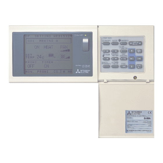
2. Outline of product The G-50A is a centralized controller with higher function than that of conventional centralized controllers, realizing to use for Web, industry first. One set of this product can control and monitor the indoor unit up to 50 sets. -
Page 8: Function
2.1 Function 2.1.1 Centralized control with G-50A The basic function of the G-50A unit is shown in the table below. Table 2-1 List of centralized control function Item Content Start/stop Switching start/stop collectively or for each group Operation mode Switching cool/dry/fan/auto/heat collectively or for each group... -
Page 9: Centralized Monitoring/Controlling By Web Browser
1 Without using a specific software, air conditioners can be controlled by your desk top PC by setting the system (Web browser function is an optional and needs license registration). 2 On the one Web screen, operation status can be monitored in a unit of G-50A (maximum 50 sets of indoor unit). - Page 10 (3) Screen image The screen images at Web monitoring are shown below. Screen of air conditioner operation status Screen of air conditioner operation status (Batch display of all groups) (Display in a unit of block) Control screen Screen to display unit under abnormal state Screen to set weekly schedule Screen to set annual schedule...
-
Page 11: Centralized Control By Integrated Software Tg-2000A
2.1.3 Centralized control by integrated software TG-2000A (1) Features 1 The indoor unit up to 2,000 sets (40 sets of G-50A) can be controlled/monitored. 2 The layout display of air conditioners provides convenience in managing and controlling. 3 Annual schedule can be set (requiring license registration in the optional function). - Page 12 (2) Caution against PC used with Integrated Software TG-2000A (Outline) a) Items to be observed in selecting PC Please select a PC of desktop type. Recommend to install a UPS system on your PC. • Since a program is required to always be •...
- Page 13 (3) Function list By utilizing the software (TG-2000A) and collecting the data of each G-50A, the operation control can be performed for up to 2000 sets in a unit of each floor or block on the PC screen.Please refer to section 2,3 for function licence.
- Page 14 (4) Screen images The screen images on the integrated software are shown as follows. Screen to display floor units Screen to display block units Screen to display whole building Control setting screen Screen to set weekly schedule Screen to set annual schedule...
-
Page 15: Remote Monitoring/Controlling - Transmitting Of Abnormal Mail
With schedule Without schedule Operation prohibition status Local remote controller Operation prohibited control prohibited Heat Others, system equipment Abnormality G-50A Abnormality K Abnormality outdoor unit Abnormality outdoor auxiliary unit transmission converter status 2.1.4 Remote monitoring/controlling - Transmitting of abnormal mail Remote controlling and monitoring can be performed from LAN, public telephone line and PHS if available. -
Page 16: Comparison Table Of Function
50A can be recorded. They can also be output in CSV format. *5 10000 cases of the contents operated from TG-2000A can be recorded. *6 Error release operation unit is as shown in the table, and all the erroneous units of G-50A system where error release operation is made are released. -
Page 17: Products List
*4 The accounting license is required. *5 The accounting license is required. *6 The control on only general purpose devices is not applied at present. It is necessary to connect G-50A without fail. *7 Other sequencer (PLC) than the pulse count software is required. -
Page 18: Specification
Output M-NET : DC24V 0.45A (Maximum loading) voltage/current DC power supply: DC12V 0.2A (Maximum loading) Load capacity Number of the loading unit: G-50A Central Controller 1 unit Temperature Environmental Operating range 0 to 40˚C/32 to 104˚F EU:~220V-240V; 0.25A 50Hz condition Storage range –20 to 60˚C/–4 to 140˚F... -
Page 19: System Design Flow
The design flow to construct the G-50A system is given below. Step-1: Selection of air conditioning equipment (Objective equipment for control, limitations and the like) Step-2: Selection of system control parts (Quantity of G-50A and other system controllers) Step-3: Construction of G-50A system (Limitation on LAN wiring and the like) -
Page 20: Step 1: Selection Of Air Conditioning Equipment
In order to construct the system, air conditioning equipment should be selected firstly. This chapter introduces the air conditioners that can be controlled with G-50A and various limitations applicable. For the detail of air conditioning equipment, please refer to the manual of the relating air conditioner. -
Page 21: Limitation On Transmission Line Wiring
The local remote controller wiring length counts for 10m or less. When it exceeds 10m, add the exceeded length to the value of “total wiring length 500m or less.” Centralized control system M-NET bus Indoor-outdoor transmission system M-NET bus Centralized Outdoor unit controller (G-50A) Indoor unit Indoor unit Power supply unit (PAC-SC50KUA) Indoor unit... -
Page 22: A-Control Transmission Line
(1) Centralized control system M-NET bus The power supply distance of the centralized control system M-NET bus can be expressed by the equation below. This represents the distance limitation to allow powering of the centralized control system M-NET bus. Exceeding this distance makes the power supply to the end equipment impossible disabling communication and control. - Page 23 [Example to use relay board] K-transmission Centralized control converter system M-NET bus Relay board Relay board K-control Mr.Slim K-control Mr.Slim K-control Mr.Slim K-control Mr.Slim air conditioner air conditioner air conditioner air conditioner Local Local Local Local indoor unit indoor unit indoor unit indoor unit remote...
-
Page 24: Step 2: Selecting System Management Parts
5. Step 2: Selecting System Management Parts 5.1 M-NET system structure There are cases in which other System Controllers (SC) besides model G-50A can be run on the G-50A system structure. In order to do so, the following outlines a number of rules to be observed for system management. -
Page 25: Regarding Power Supply Within The System
5.1.2 Regarding power supply within the system (1) Regarding power supply parts Within the G-50A system, the parts serving to supply electricity are fixed for each transmission line. Please take care there is no electricity supply overload to any one transmission line. -
Page 26: Selecting The Power Supply Unit
5.1.3 Selecting the power supply unit G-50A is driven by DC12V from the Power supply unit : PAC-SC50KUA. To communicate with the air conditioner, it is necessary to connect to the M-NET transmission line in addition. First determine whether G-50A is connected to the centralized control transmission line or to the indoor/outdoor transmission line. - Page 27 4 sets (2) Connecting to the indoor/outdoor transmission line To connect G-50A to the indoor/outdoor transmission line, use the DC12V output terminal (TB3) of PAC- SC50KUA only to supply DC12V from this terminal to G-50A. For the M-NET terminal of G-50A, connect the indoor/outdoor transmission M-NET line.
-
Page 28: When Managing A K-Control Model
K-control models. As a case example, in the case the number of G-50A units is 38 units and the address of the K transmission converter is [220], the addresses from [20] on and after are all interpreted as K-control type devices and are started up according to K-control. -
Page 29: External Input/Output
Switching of each input mode can be set from the main unit of the G-50A or by using the default setting tool. (Default value: not used) -
Page 30: External Output Signal Function
Prohibition Gray Permission DC power supply DC power supply Maximally G-50A Local arrangement board G-50A Maximally Local arrangement board * Special local arrangements are required for the relay, DC power supply (DC 12V, or DC 24V), and extension cables, etc. -
Page 31: Step 3 : Construction Of G-50A System
Below follows an explanation for the construction of a G-50A system. In order to use a PC, etc. to monitor the connections of multiple units to the G-50A and the operating status of air-conditioning units, please connect G-50A units or one or more PC’s using a LAN. -
Page 32: Centralized Monitoring Using A Pc
6.1 Centralized monitoring using a PC To monitor the G-50A system by connecting it to a PC, the two following methods are available. Perform monitoring using the browser software of the PC. (Web monitoring) Monitoring and operation can be performed without using any special software. - Page 33 Operations and monitoring available with the integrated Operations and monitoring available with the web browser (optional) software (Internet Explorer) software Remote controller operation screen Data update Data is updated automatically Data is updated manually Operation status is updated every minute, while the status Status update is invoked by changing screens (automatic of any abnormalities is updated every 3 minutes.
-
Page 34: About Floors, Blocks, And Groups
6.1.1 About floors, blocks, and groups The G-50A system can target groups, operation blocks, floors, and the whole building. In addition, for operation and monitoring, the name of the G-50A and the name of the building can be registered. Table 6-2 shows the setting registration and operation monitoring of each part while Table 6-3 shows the characters that can be used for setting each registration screen. - Page 35 Table 6-3 Name registration table Centralized Centralized Control PC Item G-50A Main Unit Default Setting Tool Control PC (Web) (integrated software) Group name Long name: Up to 20 characters Short name : Up to 8 characters Up to 10 characters...
-
Page 36: Centralized Control Pc (Local Arrangement)
6.1.2 Centralized control PC (local arrangement) Table 6-4 indicates the minimum specifications the PC required to conduct monitoring using the integrated software or the Web browser, should satisfy. Please arrange locally for a PC satisfying the specifications outlined below. Table 6-4 PC specifications Item Monitoring using the web browser Monitoring using the integrated software (PAC-TG2000A) -
Page 37: About Password Control
6.2 About password control When performing centralized control using a Web browser or the TG-2000A software, it is possible to restrict operations to approved users by setting a password to perform operations or functions please refer to section 2,3 for function licence. 6.2.1 Password control when using a Web browser (1) For general users A general user is a user who enters through the [index.html] web page. -
Page 38: About Lan
6.3.2 About the hub For the hub, there are a variety of models including the 10BASE-T/100BASE-Tx automatic switching type (switching hub), the exclusive 10BASE-T hub and the exclusive 100BASE-Tx hub. When using the G-50A, please select a 10BASE-T type. (1) What is a cascade connection? The term cascade connection refers to a series of hierarchical connections where multiple hubs are interconnected using cables and where ports can be added. -
Page 39: Lan Wire Length
6.3.3 LAN wire length A 10BASE-T network connected to the G-50A may have a maximum wire length of 100m as detailed in chapter 4.1. Consequently, when the LAN wire length exceeds 100m, the use of hubs will extend the maximum length to 500m. -
Page 40: Step4 : Implementing Annual/Weekly Schedules
7. Step 4: Implementing annual/weekly schedules With the G-50A main unit, weekly schedules can be implemented. However, when registering for a separate license (Annual/Weeky schedule), multifunctional weekly schedules and annual schedules can be performed. Please refer to section 2,3 for function licence. -
Page 41: Weekly Schedule Using The G-50A
7.1 Weekly schedule using the G-50A The following explains the outlines the weekly schedule set using the G-50A. If the weekly schedule is set using the G-50A, setting is required to be performed using the G-50A for every G-50A unit. - Page 42 Day of the week selection Selects the day of the week for the schedule to be set. Setting unit Save/do not save Selects the setting unit. Sets saving or not saving when pushing the settings save button. Block name Selects the block to be set. Schedule contents Displays the schedule contents.
-
Page 43: Weekly Schedule Of The Integrated Software
Registering the weekly/annual schedule license number in the G-50A main unit using the PC’s browser, will enable this function. In this case, the weekly schedule of the G-50A will be invalidated while the data previously set with the web monitor will be validated. -
Page 44: Step 5: Charging Function Of Energy Charge Measuring
(6) At the failure of PC, G-50A or PLC, the average apportioned value in the past may be adapted for temporary transaction as a solution. (7) As the power consumption and gas consumption is taken in the form of a pulse, the performance and accuracy are depending on that of the measuring instruments employed. - Page 45 (2) What is charge? This represents the charge of electric power, gas or water consumed by each air conditioner or tenant (In the case of using electric power count by PC direct connect (Watt Hour Meter (RS-485)), only electric power can be counted). The charge of such consumption can be calculated by the following 2 methods, and the output can be presented in printer output or file output in CSV format.
- Page 46 (6) At the failure of PC, G-50A or PLC, the average apportioned value in the past may be adapted for temporary transaction as a solution. (7) As the power consumption and gas consumption is taken in the form of a pulse, the performance and accuracy are depending on that of the measuring instruments employed.
-
Page 47: Selection Of Charging Function
8.2 Selection of Charging Function The G-50A system provides the following 3 methods to calculate the charge by measuring instruments. For the objective models that can be charged by each method, please refer to Table 4-3. (1) Manual input of electric power consumption This method is only applicable to the charging of electric power consumed by air conditioners. -
Page 48: Basic Composition And Required Materials
PC for apportioned calculation of each tenant using CSV file output from TG-2000A. Requires the table calculation software (EXCEL). Integrated software (PAC-TG2000A) Mitsubishi Electric Charge license Mitsubishi Electric Requires for each G-50A. Web monitor license Mitsubishi Electric Requires for each G-50A. Uninterrupted power sourse (UPS) Mitsubishi Electric FREQUPS A-series. - Page 49 (3) Setting items Table 8-2 shows the items of TG-2000A charging system setting and that of the charging required to carry out the electric power manual input method. Table 8-2 Setting items of the electric power manual input method Major item Subordinate item Detail Apportioning mode...
-
Page 50: Watt-Hour Meter Pulse Counting (Apportioning) Method
Table 8-4 Watt-hour meter pulse counting software Model name of watt-hour meter pulse counting software IP address Explanation PAC-YG11CDA 192.168.1.151 Fixed to the left address.* *In case of IP address needs to be changed, please ask to MITSUBISHI ELECTRIC for details. - Page 51 (3) Setting items Table 8-5 shows the setting of measuring instrument of TG-2000A, charging system and charging set items required for the electric power pulse counting (apportioning) method. Table 8-5 Setting items of the electric power pulse counting method Subordinate item Detail Major item PLC quantity setting...
-
Page 52: Measuring Instrument Pulse Counting (Direct Reading) Method
For PC spec., refer to Table 6-4. Integrated software (PAC-TG2000A) Mitsubishi Electric Charging license Mitsubishi Electric Requires for each G-50A. Web monitor license Mitsubishi Electric Requires for each G-50A. Mitsubishi Electric PLC for pulse counting can be connected up to 5 sets. -
Page 53: Power Consumption Pc Direct Reading System (Apportioning System)
Action verified with IBM, DELL, Hp Compaq Integrated software (PAC-TG2000A) Mitsubishi Electric Web monitor license Mitsubishi Electric Requires for each G-50A system Charge license Mitsubishi Electric Requires for each G-50A system RS-485 watt-hour meter For the watt-hour meter specification, refer to Table 10-3. - Page 54 (3) Setting items Table O-O shows the setting of the measuring instruments, charging system, and charge setting items of TG-2000A required to execute the power consumption pulse counting system (apportioning system). Table O-O Setting items of power consumption pulse counting system Major item Minor item Detail...
-
Page 55: Mechanism Of Charge Calculation
PLC. (3) G-50A The G-50A monitors the operation information of indoor units required by charging for each 1 minute, and holds the information in a unit of indoor unit dividing in the charging time frame. Such process is conducted by G-50A regardless of the charging methods. -
Page 56: Apportioning Calculation Method Of Outdoor Unit
The apportioning standard data of the indoor units used by each tenant (charge block) can be selected from the following two methods. (Selection by TG-2000A) These data are integrated by G-50A for each indoor unit per charging time frame and collected by TG-2000A once a day. - Page 57 (3) Apportioning by apportioning standard data To calculate [Power consumption per indoor unit], multiply the operation time by the standard data being calculated for each indoor unit per charging time frame with each capacity. Sum up this [Power consumption per indoor unit] for the indoor units inside the watt-hour meter to obtain [Indoor unit total power consumption].
-
Page 58: Apportioned Calculation Of Indoor Unit
For the models without auxiliary heater, [Fan power consumption] = [Power consumption per indoor unit] is applied. For the auxiliary heater and fan operation time, G-50A collects it from the indoor unit in a cycle of 1 minute. 0.085kW × 3.45 hours... -
Page 59: Manual Input Of Electric Power Consumption
1 Indoor unit fan operation time 2 Indoor unit auxiliary heater operation time 3 Capacity saving ratio G-50A 4 Thermostat ON time Calculating the apportioning parameter based on the data collected from G-50A PC for centralized control (Integrated software) Preparation Apportioning parameter file Using “Charging ratio support software,”... - Page 60 (5) Charging ratio support software By using “Charging ratio support software” (EXCEL) provided with the integrated software, the charge apportioning and bill preparation for each tenant can be performed. Through the reading of the operation time data file prepared by TG-2000A from the menu screen of the charging ratio support software, automatic calculation will be carried out.
-
Page 61: In The Case Of Measuring Instrument Pulse Counting (Direct Reading) Method
In this method, the charge may be calculated by multiplying the values of the measuring instruments provided by the unit price and further adding the standard charge. In the case of the measuring instrument pulse counting method, the operation information of air conditioners is not required, but the license registration to G-50A is essential. -
Page 62: Output Of Charging Data
8.5 Output of Charging Data Thanks to the use of TG-2000A, the apportioned result and power consumption can be output per each watt-hour meter, unit price or block. The output content (format) differs depending on the content of “Charging relations” set among the user setting items on the initial setting screen. Select the output format to meet your purpose of use. -
Page 63: Charging Method
8.6 Charging Method As shown below, the charging in this system can be set as follows. Divide the time frame 0:00 ~ 24:00 into 10 charging frames, and assign 5 charging unit prices to each charging frame respectively for setting. Please note that each setting is common within the system. -
Page 64: Caution For Using Charging Function
PC. (for example to print on paper) The registration of charge license to G-50A unit is required for all units registered to the centralized control PCs. Without the registration, the air conditioner charging function does not operate normally. -
Page 65: Step 6: Energy Saving/Peak Cut Control
9. Step 6: Energy Saving/Peak Cut Control Here the energy saving control or peak cut control to be performed by G-50A is set. This setting is essential in conducting the energy saving control or peak cut control. As this function is optional, the license registration to G-50A is necessary to use. -
Page 66: Outline
The integrated software sets the following energy saving items and energy saving time to G-50A control per outdoor unit and the set G-50A conducts the energy saving operation for the outdoor unit. Peak cut control Connecting the watt-hour meter (PLC) allows conducting energy saving operation meeting the power consumption. -
Page 67: Energy Saving Control/Peak Cut Control
The energy saving control includes the items listed on Table 9-2, and they can be set from the integrated software for each block freely. After setting, G-50A conducts energy saving control on to the air conditioning group within the operation block in a unit of 3 (3/6/9/15/30 minutes) within a 30 minutes not allowing overlapping the control time. - Page 68 (= 15 min./5 groups). (If indivisible, round it to the nearest whole number.) Figure 9-3 Example of indoor unit energy saving control In the case of the block setting stepped across from TG-2000A to G-50A, only the unit Notice controlled by the G-50A is set as the block on the G-50A.
- Page 69 Mitsubishi Electric Use Ver.2.5 or later. Energy saving control license Mitsubishi Electric Requires for each G-50A. Web monitor license Mitsubishi Electric Requires for each G-50A. The control time may be overlapped depending on the group numbers in the block and control time.
-
Page 70: Peak Cut Control
Use Ver.4.1 or later. Centralized controller (G-50A) Mitsubishi Electric Use Ver.2.5 or later. Peak cut control license Mitsubishi Electric Requires for each G-50A. Web monitor license Mitsubishi Electric Requires for each G-50A. Mitsubishi Electric Usable commonly with PLC for measuring instrument charging. - Page 71 Selecting target G-50A for setting Select G-50A objective for peak cut setting. Setting control detail and time Batch setting for whole Select the detail and time of indoor building is possible. unit peak cut control. Setting levels Setting energy saving ineffective...
-
Page 72: Energy Saving Control Status · History Monitor
Daily and monthly reports <Automatic output file> The automatic output file is automatically created daily (or monthly) as TG-2000A gathers information from G-50A and PLC. Therefore it is not created if TG-2000A is finished. CAUTION <Manual output file> You can manually output each file from the TG-2000A tool bar. Monthly data will be created from TG-2000A database while daily data for the day, the day before and two days before will be collected from G-50A. - Page 73 (3) Creation of daily report/monthly report trend graphs You can turn a CSV file (trend graph) into a graph using “Trend graph Idisplay tool” that comes with TG-2000A. Refer to the Item 14.2 for details. Figure 9-7 Peak cut status history daily report example...
-
Page 74: Energy Saving Control System Design Flow
If you do a peak cut control, you will set the Watt-hour meter in increments of G-50A. The control level will be set at 5 steps. As a concept, you will consider the target contract demand based on the current contract demand, and determine the value for the final level (Level 4). -
Page 75: Step 7: Selection Of Measuring Instruments
Table 10-2 Recommended watt-hour meter Model name Description Maker Mitsubishi Electric Model name Single-phase 2 wire system Single-phase 3 wire system, three-phase 3 wire system Others Up to 32 units of Watt-hour meter can be used per 1 unit of PLC. - Page 76 (2) Power consumption PC direct reading system (RS-485WHM) Please use the RS-485 watt-hour meter shown in Table 10-3. Table 10-3 Model name of RS-485 watt-hour meter specified Model name Detail Maker name XXXXX XXXXX XXXXX XXXXX Model name XXXXX XXXXX XXXXX XXXXX Remarks...
-
Page 77: Step 8: General Purpose Equipment Control
TG-2000A monitor screen. System equipment is controlled by PLC. “General-purpose control software: PAC-YG21CDA” needs to be installed in PLC. (For PAC-YG21CDA Ver.1 series, no licensing registration needed for G-50A.) Lighting Other systems PLC (general purpose control Other manufacturer’s packaged... -
Page 78: Outline
11.1 Outline PLC will be used to control general-purpose equipment, along with a DI board (DC input unit) and a DO board (transistor output unit). One icon will be shown on the TG-2000A monitor screen to represent one system equipment, and you can operate (one shot pulse output), monitor the status, and monitor for error (level input). -
Page 79: Determine The Control Items
11.2.2 Determine the control items. After you determine the equipment to be connected, define the control items for each equipment. For instance, whether you want to operate the instrument (ON and OFF) and monitor it, including error monitoring, or just watch for failure (malfunction). For ON and OFF, status output signal from the instrument changing the icon status (color) is the basic mechanism. -
Page 80: Plc Assignment
Integrated software (PAC-TG2000A) Mitsubishi Electric Use Ver. 4.1 or later version. Web monitor license Mitsubishi Electric Requires for each G-50A. Mitsubishi Electric Make sure DI board and DO board are mounted. General-purpose control software Mitsubishi Electric This software should be installed in PLC. -
Page 81: Setting Of Tg-2000A
11.2.5 Setting of TG-2000A After the assignment of terminals, TG2000A should be configured. For each general-purpose instrument, what to be controlled and monitored should be set up in TG-2000A. Selection of PLC No. Select the PLC. Number of connected PLC’s General-purpose This shows how many instrument button... -
Page 82: Step 9: Determining Number Of Plc Units
G-50A uses PLC (Programmable Logic controller) to provide measuring instrument charging function (pulse count system), general-purpose control function and other functions. The PLC to be used is “MELSEC-Q series” by Mitsubishi Electric, and Figure 12-1 shows the standard configuration of G-50A system. -
Page 83: Plc's For Pulse Count Function
12.2 PLC’s for Pulse Count Function 12.2.1 Restriction on the number of units To carry out measuring instrument charging function or energy saving peak cut control, you will need to have the standard configuration explained in the previous chapter plus a DC input unit. One DC input unit can support 16 contacts, so you can connect up to 16 measuring instruments. -
Page 84: Plc For General-Purpose Control Function
12.3 PLC for General-purpose Control Function 12.3.1 Restriction on the number of units When performing general-purpose functions, you will need the standard composition explained in 12.1, DC input unit, and transistor output unit. DC input unit and transistor output unit each supports 16 contacts. One system instrument uses two contacts, so, up to 8 general-purpose units can be connected. -
Page 85: Terminal Connection Diagram
12.3.2 Terminal connection diagram Figure 12-5 shows the connection to terminal boards in DC input unit (QX40) and transistor output unit (QY40P). Since DC input unit and transistor output are non-voltage, you have to provide a DC24V power supply (DC12V is unacceptable) and a DC24V or DC12V power supply for transistor output unit separately. If the facility instrument side has a level input, you have to prepare a pulse-level conversion circuit separately, as shown in the figure 12-6. -
Page 86: Plc Software
12.4 PLC Software In order to use various functions based on PLC, integrated software is necessary. Some functions require license number registration in the G-50A main body. PLC needs to have software to implement various functions. Table 12-2 Items needed for each function... -
Page 87: External View Of Sequencer
12.5 External View of Sequencer External dimension of each PLC unit is shown below. Base unit 4-mounting screw (M4 × 14) 44.1 15.5 CPU unit Power supply unit D02CPU 061P-A1 POWER MODC ERR. USER BAT. BOOT 98.15 98.00 PULL PULL RS-232 89.30 27.40... -
Page 88: Plc Wiring Diagram
(for reference). Depending on the setting environment, however, unnecessary components may be included. In this case, consult with a contractor to decide whether or not they are necessary. Power Power source source unit (Q61P-A1) Circuit AC100V G-50A Circuit Insulating breaker breaker transformer CPU unit for main Arrestor... -
Page 89: Step 10:Determination Of Address For Air Conditioning Instrument And Pc For Control
Table 13-1 Address setting range for M-NET models Address range Models Remarks G-50A Basically, the address range of G-50A is fixed to “000” at the factory. 001~050 Indoor unit, OA Processing Unit, Lossnay, M- NET interface 051~100 Outdoor unit, BC controller, constant-capacity... -
Page 90: Setting Method For Connecting G-50A To Exclusive Lan
[192.168.1.1] in sequence. For example, assign [192.168.1.1] for the first G-50A, [192.168.1.2] for the second G-50A, and so and so in sequence. In addition, set a PC for monitoring on the Web to monitor G-50A and set the initial setting tool and the like also to the network address in the same system. -
Page 91: Setting Method For Connecting G-50A To Existing Lan
Communications with G-50A and PLC are possible by making a router convert the address by assigning an IP address corresponding to the IP address form on the backbone LAN also to G-50A and PLC to access to them by the use of the address. -
Page 92: Setting For Remote Monitoring
Hub for 10BASE-T Refer to Table 13-4. This component is necessary, when the number of G-50A and that of a PC to be connected is over the number of dialup-router-built-in hub ports and when wiring distance is expanded. 10BASE-T LAN straight cable Refer to Table 13-4. - Page 93 In case of setting to the same system, data communications are not available by way of the dialup line, because telecommunications data are input from the LAN port of the PC. A gateway address can not be set only from the initial setting tool. (Other addresses can be set from G-50A.)
-
Page 94: Setting Of Abnormal Mail Transmission System
Hub for 10BASE-T Refer to Table 13-4. This component is necessary, when the number of G-50A and that of PC to be connected are over the number of dialup-router-built-in hub ports, and when wiring distance is expanded. 10BASE-T LAN straight cable Refer to Table 13-4. -
Page 95: Preparations Before Performing Abnormal Mail Transmission
(2) Network setting of G-50A Set the IP address, subnet mask, and gateway address of G-50A by means of the initial setting tool. Set the IP address of a dialup router to gateway address. -
Page 96: System Using Optical Cable For Lan
13.5 System Using Optical Cable for LAN As stated in item 0, the LAN wiring length in G-50A system can be expanded up to 500m by connecting a hub in the form of cascade connection. However, in the system in which the wiring length requires 500m or more on the system configuration, Optical cable if used can be extended up to 500m or more. -
Page 97: Step 11: Confirmation Of Other Functions
14. Step 11: Confirmation of Other Functions 14.1 Individual Browser Function The Ver.2.5 of G-50A or later is provided with the individual browser function. (License registration required) This function is not available with G-50A versions earlier than 2.5 (For administrator’s web browser function, web monitor license registration is required). -
Page 98: User Registration From Administrator
The user names of administrators and air-conditioners available are displayed on the screen. (All the groups of air conditioners under the control of G-50A are displayed Air conditioners which can on the screen.) be operated Air conditioners which can be General user information operated are displayed. -
Page 99: Trend Data Output Function
G-50A and PLC. CAUTION Therefore, in the environment where TG-2000A is not connected full-time or in case that TG-2000A can not communicate with G-50A or PLC, phenomena such as missing of data and no formulation of a file may be induced. -
Page 100: Preparation For Outputting Parameter Files
14.2.2 Preparation for outputting parameter files In order to output parameter files, a setting on the window of TG-2000A initial setting screen is required. The following conditions allow each trend data to be output. 1 Trend data related to electric power (There are 3 kinds): “Electric power PLC included”, “Watt-hour meter and measuring instrument connected”, and “Trend”. -
Page 101: Example Of Csv Files Output
In addition, although each relevant datum is shown in each data column, the data value with the following mark indicates abnormal data. [-99] : Indicates that TG-2000A have failed to collect normal data from G-50A and PLC. ] (Blank): Indicates that the power source for TG-2000A has been off. (1) Trend data for temperature... - Page 102 Hourly basis in a designated period (5) Data for peak cut (Daily report) Electric power consumption of every G-50A in a unit of 30 is displayed on the screen. A control level of electric energy of every G-50A in a unit of 2 minutes is displayed on the screen.
-
Page 103: Graphing Trend Data
14.2.5 Graphing trend data A trend graph can be developed from a CSV file output as trend data by means of “Support tool for developing trend graphs” in the CD-ROM for TG-2000A installation. [Essentials for display of a trend graph] Excel 2000/XP An output file of trend data or peak cut data “Support tool for drawing trend graphs (Excel)”... -
Page 104: Initial Setting Tool
G-50A at local site. In addition, since the following items cannot be set with G-50A without using the initial tool, they must be registered without fail by means of the initial setting tool. -
Page 105: Composition Of Initial Setting Tool
64MB or more Interface LAN port In case of connecting to G-50A with LAN cable (PAC-YG00FA) for (Exclusive 10BASE-T recommended) initial setting, if the LAN port of a PC is of 10/100BASE-T automatic changeover type, it may not be connected normally. -
Page 106: Connection To G-50A
G-50A and a PC. As a serial number is recorded on the cover, be sure not to confuse the cover for G-50A with other cover for G-50A when the cover is attached after the completion of initial setting. -
Page 107: Other Function
16.1 Auto-Changeover Function (Automatic Changeover of Cooling/Heating Operation) For the outdoor unit (Y Series) without the function of cooling/heating simultaneous operation, G-50A can judge whether cooling or heating should be selected by observing a difference between the set and inlet temperature of each indoor unit, and collectively changes over the operation of cooling/heating of indoor units connected to the outdoor unit. -
Page 108: Auto-Changeover Mode
16.1.1 Auto-changeover mode Under this mode, the difference of the set and inlet temperature of air conditioning groups (excluding the group under fan operation or stopping) contained in a same changeover block is measured to assign points to each group accordingly, and from this resultant total, the changeover mode (cooling/heating) is judged for selection. - Page 109 Mitsubishi Electric Air Conditioning Network System Centralized Controller G-50A and Integrated Centralized Control Software TG-2000A Technical Manual Issued in Dec. 2003 F1105-302 (MDOC) Contents effective Dec. 2003 Specifications subject to change without notice.
- Page 110 3400 Lawrenceville Suwanee Road Suwanee, Georgia 30024 ● Toll Free: 800-433-4822 Toll Free Fax: 800-889-9904 ● www.mrslim.com Specifications are subject to change without notice.
Need help?
Do you have a question about the G-50A and is the answer not in the manual?
Questions and answers