
Related Manuals for BK Precision PVS10005


Summary of Contents for BK Precision PVS10005
-
Page 1: Power Supply
Model: PVS10005, PVS60085, PVS60085MR High Power Programmable DC Power Supply USER MANUAL... -
Page 2: Safety Summary
Safety Summary The following safety precautions apply to both operating and maintenance personnel and must be followed during all phases of operation, service, and repair of this instrument. Before applying power to this instrument: Read and understand the safety and operational information in this manual. - Page 3 Category I (CAT I): Measurement instruments whose measurement inputs are not intended to be connected to the mains supply. The voltages in the environment are typically derived from a limited-energy transformer or a battery. Category II (CAT II): Measurement instruments whose measurement inputs are meant to be connected to the mains supply at a standard wall outlet or similar sources.
- Page 4 ensure it is appropriate for your country of use. Ground the Instrument To minimize shock hazard, the instrument chassis and cabinet must be connected to an electrical safety ground. This instrument is grounded through the ground conductor of the supplied, three-conductor line power cable.
- Page 5 In the presence of noxious, corrosive, or flammable fumes, gases, vapors, chemicals, or finely-divided particulates. In relative humidity conditions outside the instrument's specifications. In environments where there is a danger of any liquid being spilled on the instrument or where any liquid can condense on the instrument.
- Page 6 instrument from service, label it as not to be operated, and return the instrument to B&K Precision for repair. Notify B&K Precision of the nature of any contamination of the instrument. Clean the instrument only as instructed Do not clean the instrument, its switches, or its terminals with contact cleaners, abrasives, lubricants, solvents, acids/bases, or other such chemicals.
- Page 7 after making the measurements by testing with known-operating voltage sources and test for both voltages. Do not attempt any service or adjustment unless another person capable of rendering first aid and resuscitation is present. Do not insert any object into an instrument's ventilation openings or other openings.
- Page 8 This instrument contains one or more cooling fans. For continued safe operation of the instrument, the air inlet and exhaust openings for these fans must not be blocked nor must accumulated dust or other debris be allowed to reduce air flow. Maintain at least 25 mm clearance around the sides of the instrument that contain air inlet and exhaust ports.
-
Page 9: Compliance Statements
Compliance Statements Disposal of Old Electrical & Electronic Equipment (Applicable in the European Union and other European countries with separate collection systems) This product is subject to Directive 2002/96/EC of the European Parliament and the Council of the European Union on waste electrical and electronic equipment (WEEE), and in jurisdictions adopting that Directive, is marked as being put on the market after August 13,... -
Page 10: Ce Declaration Of Conformity
CE Declaration of Conformity This instrument meets the requirements of 2006/95/EC Low Voltage Directive and 2004/108/EC Electromagnetic Compatibility Directive with the following standards. Low Voltage Directive EN61010-1: 2001 EMC Directive EN 61000-3-2: 2006 EN 61000-3-3: 1995+A1: 2001+A2: 2005 EN 61000-4-2 / -3 / -4 / -5 / -6 / -11 EN 61326-1: 2006... -
Page 11: Safety Symbols
Safety Symbols Refer to the user manual for warning information to avoid hazard or personal injury and prevent damage to instrument. Electric Shock hazard On (Supply). This is the AC mains connect/disconnect switch on the front of the instrument. Off (Supply). This is the AC mains connect/disconnect switch on the front of the instrument. - Page 12 CAUTION indicates a hazardous situation which, if not avoided, will result in minor or moderate injury WARNING indicates a hazardous situation which, if not avoided, could result in death or serious injury DANGER indicates a hazardous situation which, if not avoided, will result in death or serious injury.
-
Page 13: Table Of Contents
Table of Contents Safety Summary ..............i Compliance Statements ..............viii Safety Symbols ..................x General Information ............. 1 Product Overview............... 1 Package Contents ............... 2 Product Dimensions ..............3 Front Panel Overview ..............4 Front Panel Description ..............4 Keypad Overview ............... - Page 14 Preliminary Check ..............15 Warm-up Time ................15 Output Check .................. 15 Check Model and Firmware Version ..........17 Front Panel Operation ..........19 Menu Options ................19 How to Access the Menu..............20 Configure Voltage/Current Output .......... 21 Setting Voltage ................21 Setting Current ................
- Page 15 PV Simulation ................57 Program Function ..............60 Overview ..................60 Configure Program Parameters ............61 Timer Function ................. 65 3.10 Slew Rate Setting ..............66 Remote Operation ............67 Interface Configuration ............67 Parameter Definition ..............78 Error/Event List ................ 78 SCPI Common Commands ............
- Page 16 External Voltage Programming Calibration ......98 External Current Programming Calibration ......99 CC Calibration of External Voltage ......... 100 CC Calibration of External Current ......... 101 Troubleshooting Guide ..........103 General ..................103 Remote Control ................104 Specifications............105 SERVICE INFORMATION ........... 108...
-
Page 17: General Information
1 General Information 1.1 Product Overview B&K Precision models PVS60085, PVS60085MR, and PVS10005 are high voltage programmable DC power supplies with single outputs that offer the maximum power output up to 5100 watts (0 - 600 V / 8.5 A or 0 - 1000 V / 5 A). -
Page 18: Package Contents
Report any damage to the shipping agent immediately. Save the original packing carton for possible future reshipment. Every power supply is shipped with the following contents: 1 x PVS10005, PVS60085, or PVS60085MR Power Supply 1 x User Manual 1 x AC Power Cord ... -
Page 19: Product Dimensions
1.3 Product Dimensions The PVS10005, PVS60085, and PVS60085MR power supply’s dimensions are approximately: 420mm (16.54in) x 88mm (3.46in) x 532mm (20.95in) (WxHxD). These 2U supplies are designed to fit in a standard 19-inch rackmount. Note: All dimensions in the figures below are measured in millimeters (mm). -
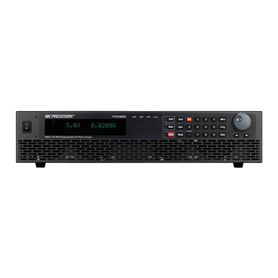
Page 20: Front Panel Overview
1.4 Front Panel Overview Figure 1.3 – Front Panel Overview Front Panel Description Power On/Off switch Vacuum Fluorescent Display OVP, OCP, OPP indicators Keypad lock indicator Function keys Numeric keys Rotary Knob Left, Right cursor keys... -
Page 21: Keypad Overview
1.5 Keypad Overview Figure 1.4 – Keypad Overview Keypad Description Shift key Enables access to secondary functions (Labeled in blue) Meter display button Toggles display between set and measured voltage and current. On/Off Controls the output state. Vset / Slope button Configures output voltage or sets the rise and fall times of the output voltage. - Page 22 Decimal / Local button Inputs a decimal point for values or sets the instrument back to local mode Numeric keypad Enters numeric values for various parameters. Menu button Allows access to the power supply menu settings. Program button Enters program mode settings menu. Enter Confirms setting/parameter changes.
-
Page 23: Rear Panel Overview
1.6 Rear Panel Overview Figure 1.5 – Rear Panel Overview Rear Panel Description Output and remote sense terminals USB interface RS-485 interface Analog programming interface (DB25 connector) AC input receptacle Earth ground connection GPIB interface Ethernet (LAN) interface RS-232 interface... -
Page 24: Display Overview
1.7 Display Overview Figure 1.6 – Display Overview Display Description Set/Measured voltage Settings display Displays parameter settings such as OVP, P-max, Rise/Fall Measured power output Set/Measured current Indicates output is disabled Indicates constant current (CC) operation Indicates constant voltage (CV) operation Indicates remote mode Addr Indicates remote communication activity... -
Page 25: Getting Started
2 Getting Started Before connecting and powering up the instrument, please review and go through the instructions in this chapter. 2.1 Input Power and Fuse Requirements Input Power The supply has a universal AC input that accepts line voltage input within: AC Input: 170 V –... - Page 26 The included AC power cord is safety certified for this instrument operating in rated range. To change a cable or add an extension cable, be sure that it can meet the required power ratings for this instrument. Any misuse with wrong or unsafe cables will void the warranty. SHOCK HAZARD: The power cord provides a chassis ground through a third conductor.
- Page 27 Figure 2.1 – AC Power Connection Diagram Refer to the descriptions below to connect the other end of the AC power cord to the AC distribution panel. Do NOT plug the AC power cord into the wall socket prior to connecting ALL three AC power wires to the rear panel and securely mount the safety metal housing over the input receptacle.
-
Page 28: Fuse Replacement
Figure 2.2 – AC Power Cord Fuse Replacement This power supply does not require a fuse that is user replaceable. There is an internal fuse, in which if blown, may indicate a malfunction in the unit. In this event, contact B&K Precision. Any disassembling of the case or changing the fuse not performed by an authorized service technician will void the warranty of the instrument. -
Page 29: Output Connections
cabinet. Rack mount brackets must be assembled before mounting the unit in a rack. Refer to the following figure to assemble the rack mount brackets. Figure 2.3 – Rack Mount Bracket Assembly 2.3 Output Connections The main DC output terminal is a screw type terminal block located in the rear panel. - Page 30 Imax(A) mΩ/meter 13.2 33.5 52.8 Table 1 – Wire Gauge Rating Before connecting wires to the output terminals, turn OFF the power supply to avoid damage to the instrument and the device under test (DUT). For safety, load wires must have a wire gauge size large enough to prevent overheating when the power supply operates at maximum short circuit output current.
-
Page 31: Preliminary Check
2.4 Preliminary Check Complete the following steps to verify that the power supply is ready for use. Verify AC input voltage Verify and check to make sure proper AC voltages are available to power the instrument. The AC voltage range must meet the acceptable specification as explained in “2.1 Input Power and Fuse Requirements”. - Page 32 Voltage Check Follow the steps below to check voltage output with no load connected. 1. Turn ON the power supply. The display will show the OFF annunciator above the voltage display. 2. Enable the output by pressing , and the LED next to the button will be lit.
-
Page 33: Check Model And Firmware Version
3. Using the numeric keypad or the current adjust knob, enter a small current value (i.e. 1.000 A). If entering with numeric keypad, press first, then enter the value and press The current display will now show the value you entered. 4. - Page 34 3. The model is shown above as PVS10005. 4. Press once again and the firmware version will displayed. 5. The firmware is shown above as 1.52. 6. Press twice to exit the menu and return to the normal display.
-
Page 35: Front Panel Operation
3 Front Panel Operation 3.1 Menu Options All settings and parameters can be configured from the built-in menu system of the power supply. To access the menu, press The menu system is divided into 5 sections and are organized as follows: SYSTEM COMM Select and configure communication interface. -
Page 36: How To Access The Menu
How to Access the Menu Before using the instrument, it is important to be familiarized with its menu structure and learn how to view or change settings and parameters. Follow the steps below to guide you in selecting menu options. 1. -
Page 37: Configure Voltage/Current Output
8. To exit the menu at any time, press twice. 3.2 Configure Voltage/Current Output Voltage and current can be set from the front panel. Remote sense is also available on the rear panel for voltage compensation at the output. Setting Voltage Follow the steps below to set the output voltage: 1. -
Page 38: Setting Current
value if the test is needed. Setting Current Follow the steps below to set the output current: 1. From the normal front panel display, users can use either the current adjust knob or the numeric keypad to enter the setting current. -
Page 39: Remote Sense
Remote Sense Remote sense can be used to compensate for voltage drops up to 6 V (PVS60085/MR) or 10 V (PVS10005) due to resistance from test leads connected to your device under test (DUT), thus providing more accurate output voltage. The power supply is initially set up for local sense mode by default. - Page 40 output is connected to the negative end (-) of the load. When this sensing mode is selected the wires connecting between DC outputs to the load must be as short as possible. The local sense is the default configuration with shorting bars connect between (+S) to (+) and (-S) to (-).
-
Page 41: Voltage/Current Measurement
2. Use a small flat blade screwdriver to loosen the wire connection connected between Vo+ and S+ and S- and Vo-. 3. Connect the S+ to the DUT’s positive (+) terminal, and connect the S- to the DUT’s negative (-) terminal. 4. - Page 42 The following table shows the various messages that may alert the user: System message Description IAC TOO HIGH! AC input current too high VBUS NO CHARGE! Internal PFC VBUS is not charged VAC TOO LOW! AC input voltage too low VAC TOO HIGH! AC input voltage too high Cannot read or write the internal non-...
-
Page 43: System Menu
3.5 SYSTEM Menu All setup procedures and settings explained in this section can be accessed from the SYSTEM menu. To access this menu, press When SYSTEM is blinking, press Remote Communication Configuration To set up remote interface connections and settings, refer to chapter “4 Remote Operation”. - Page 44 2. Use the rotary knob or the numeric keypad to enter the storage group. Select between 0 – 9. Press to save selection. 3. To exit the menu at any time, press twice. Save Settings 1. Set up output voltage and current settings that you want to save.
-
Page 45: Enable/Disable Key Sound
Instrument settings can only be recalled when the instrument enters this mode. 2. Use the keypad to enter the memory location you want to recall. Enter between 0 – 9. The voltage and current settings of that memory location will be shown on the bottom of the display. 3. -
Page 46: Restore Factory Default Settings
2. The instrument will return to the normal display and all settings are now restored back to factory default. The table below lists some of the factory default settings. Table 2 - Factory Default Settings Item Parameter PVS60085/MR PVS10005 Voltage 10.0 V 10.0 V Output Current 1.0000 A 1.0000 A... - Page 47 CC to CV Voltage 6 V/ms 4 V/ms Slope Current 85 mA/ms 20 mA/ms Mode Parallel Role MASTER MASTER Enable NOT ACTIVE NOT ACTIVE Voltage FRONT FRONT Current FRONT FRONT External Control Program range 5V/5kΩ 5V/5kΩ Monitor range Shut off logic OFF/LOW OFF/LOW Beep...
-
Page 48: Configure Power-On State
GPIB Address RS-232C Baud, parity, data, stop 9600, N, 8, 1 9600, N, 8, 1 Baud, parity, data, stop 9600, N, 8, 1 9600, N, 8, 1 RS-485 Address Mode AUTO AUTO IP address 0.0.0.0 0.0.0.0 Mask address 0.0.0.0 0.0.0.0 Gateway address 0.0.0.0 0.0.0.0... -
Page 49: Config Menu
3. Select one of the settings wanted during power up, and press to save changes. If USER has been selected, set user defined voltage, current and output state. 4. To exit the menu at any time, press twice. 3.6 CONFIG Menu All setup procedures and settings explained in this section can be accessed from the CONFIG menu. - Page 50 Figure 3.2 – Output Limit Settings Graph Note: At any time during operation, when you are unable to set to a desired voltage or current, check these limit settings to make sure the set value is within the limit’s range. The shaded area illustrated above is the settable range of the output voltage and current.
-
Page 51: Protection Settings
2. Use the keys to select the limit setting value of VMAX, VMIN, IMAX, and IMIN. Press to confirm selection. 3. Use the numerical keys to set the limit value and press confirm the setting. 4. Press several times to exit the menu setting. Protection Settings Configure Over Voltage Protection (OVP) The PVS overvoltage protection utilizes a hardware comparator that... - Page 52 4. Use numerical keys directly or use keys with rotary adjustment followed by to confirm the OVP value. 5. Press several times to exit the menu setting. 6. If the OVP is on, the OVP LED indicator will be lit up. When OVP protection is tripped during operation, the output will turn off and the following OVP status message will display: To clear the trip status, press...
- Page 53 4. Use rotary to select the OCP ON or OFF followed by 5. Use numerical keys directly or use keys with rotary adjustment followed by to confirm the OCP value. 6. Press several times to exit the menu setting. 7. If the OCP is on, the OCP LED indicator will be lit up. When OCP protection is tripped during operation, the output will turn off and the following OCP status message will display: To clear the trip status, press...
- Page 54 4. Use rotary to select the OPP ON or OFF followed by 5. Use numerical keys directly or use keys with rotary adjustment followed by to confirm the OPP value. 6. Press several times to exit the menu setting. 7. If the OPP is on, the OPP LED indicator will be lit up. When OPP protection is tripped during operation, the output will turn off and the following OPP status message will display: To clear the trip status, press...
- Page 55 4. Use rotary to select the OPP ON or OFF followed by 5. Press several times to exit the menu setting. When CV to CC protection is tripped during operation, the output will turn off and the following CV to CC status message will display: To clear the trip status, press once.
-
Page 56: External Analog Control
When CC to CV protection is tripped during operation, the output will turn off and the following CC to CV status message will display: To clear the trip status, press once. External Analog Control To control or monitor the output of the power supply using external signals, refer to the following figure of the DB25 connector located in ○... - Page 57 Figure 3.3 – DB25 Pinout Signal Description Open: AMODE, output button is disabled BMODE, output is OFF ○ Enable+ Short to Enable: AMODE, output button is enable BMODE, output is ON Ground Ground Open: front panel control ○ Local/Analog Short to ground: rear analog control...
- Page 58 Input 0-5 V / 0-5 kΩ or 0-10 V / 0-10 kΩ for ○ Voltage voltage output setting, full scale input Program equals maximum output voltage Input 0-5 V / 0-5 kΩ or 0-10 V / 0-10 kΩ for ○ Current current output setting, full scale input Program...
- Page 59 High: front panel controlled ○ Local/Analog State Low: rear analog controlled Ground Ground Output 0-5 V / 0-10 V represents power ○ Current supply output current, full scale input Monitor equals maximum output current Enabling/Disabling External Control Follow the steps below to configure and enable the external control interface.
- Page 60 Enable+ (Pin 1) and Enable- (Pin 14) are opened, the button is disabled and the power supply’s output will remain OFF. Pressing the button will not turn ON the output, and the display will also show ENA. When Enable+ (Pin 1) and Enable- (Pin 14) are shorted, the button is enabled.
- Page 61 Disable Opened ACTIVE - BMODE Shorted Disable Local/Analog Control Pin 8 can be used to select the control mode (local or analog) of the power supply’s output. When the input command for this pin is at high level (or open), the control mode will be local. When input command for this pin is at low level (or shorted to GND), the control mode will be analog.
- Page 62 Power OK Signal Pin 16 is used to indicate whether a fault condition is present in the power supply. Normally this pin will output a logic high (5V). When a fault occurs, this pin will output a logic low (0V). Fault conditions are defined as follows: 1.
- Page 63 2. Press button three times until EXTCTRL is blinking and press 3. Press button one time to select VOLTAGE and press 4. Use the rotary knob to select EXT-V (external voltage) or EXT-R (external resistance) option and press . To have front panel control, select FRONT.
- Page 64 value by connecting a resistance value of 0-5 kΩ (0-5 V / 0-5 kΩ mode) or 0-10 kΩ (0-10 V / 0-10 kΩ mode) between Pin 9 and Pin 22 as shown below. 0 – 5 kΩ 0 – 10 kΩ Figure 3.5 - Analog Voltage Programming Diagram (Resistor Mode) Current Program This function is able to program the current output by connecting an...
- Page 65 6. Now use the rotary knob to select between 10V/10K or 5V/5K and press 7. Press several times to exit the menu setting. Voltage Mode Under voltage mode, the user may control the full scale current output value through Pin 10, by inputting a voltage level of 0-5V (0-5 V / 0-5 kΩ mode) or 0-10V (0-10 V / 0-10 kΩ...
- Page 66 Voltage Monitor This function is able to monitor the voltage output using Pin 11 and one of the ground pins (i.e. Pin 22), which can be connected to a digital voltage meter (DVM) or other voltage monitoring device, as shown below.
- Page 67 of the ground pins (i.e. Pin 23), which can be connected to a digital voltage meter (DVM) or other voltage monitoring device, as shown below. The output control must be in analog mode to use this function. The monitoring of the output voltage range (which reflects 0 to full scale of the power supply’s output voltage) can be selected between 0-5 V and 0-10 V.
- Page 68 Follow the steps below to configure the shut off control. 1. Press the button and press the button one time until CONFIG is blinking and press 2. Press button three times until EXTCTRL is blinking and press 3. Press button five times to select SHUT OFF and Press The following will be on the display: 4.
-
Page 69: Parallel Operation
Note: Shut off can only occur when the power supply receives an edge trigger. Maintaining that pin constantly at a high level or low level will not trigger a shut off. EXTCTRL EXTCTRL Shutoff Output Display ENABLE SHUT-OFF (Pin 15) OFF/Low Not Active ON/OFF... - Page 70 Figure 3.10 – Parallel Connection Diagram After wiring is complete, configure one of the supplies as the Master and the other three as Slave A, B, and C. After one of the supplies is configured to be the Master, it will start searching for all Slaves that are connected to the Master.
- Page 71 2. Press button four times until PARALLEL is blinking and press 3. Press to select the parallel MODE. 4. Use the rotary knob to select the setting of OFF or ON and press 5. Press button one time until ROLE is blinking and press 6.
- Page 72 In parallel mode, the slave unit is remote controlled by the master unit. The keypad will be locked. To exit the parallel mode, press key to access the parallel mode ON/OFF setting in the menu. Turn off to disable parallel mode control. Master Unit After all of the slave units have been set, the master unit can be set by the same procedure with the role set to MASTER.
-
Page 73: Pv Simulation
While in parallel connection mode, the output voltage of each power supply should be set to equal value. If the voltage value of each unit is not the same, the higher output voltage will feed back to the lower voltage unit and damage its internal components. - Page 74 effectiveness of the inverter’s MPPT algorithm. Figure 3.11 – PV Simulation Curve Solar arrays consist of multiple solar cells characterized by a complex voltage and current profile that is represented in an I-V curve. The I-V curve of a solar array can be generated automatically or manually using one of the following two methods: a) Automatically generate the I-V curve by specifying four input parameters: Isc (short circuit current), Voc (open circuit voltage),...
- Page 75 the I-V profile. b) Manually generate the I-V curve by creating a user-defined table of points in the SAS software. Up to 1024 I-V points can be downloaded to the PVS supply’s non-volatile memory. Once one of these I-V curves has been selected and set from the front panel, the power supply will operate in PV mode and output a voltage and current value according to the active I-V profile and load conditions.
-
Page 76: Program Function
3. Use the keys to move the cursor to the CURVE field and use the rotary knob to select the desired curve number. The curve number can be 1-16 or TABLE (table of up to 1024 I-V points.) 4. Once again, use the keys to move the cursor to the EDIT field and press . -
Page 77: Configure Program Parameters
illustration of how programs are structured, stored, and recalled. … Repeat Program Next Program (P3) Figure 3.12 – Program Structure Illustration Configure Program Parameters Actions The program function is used to edit a test pattern composed by steps. Each step contains the voltage, current, time, and action. There are three types of actions that can be set: ON, OFF, and END. - Page 78 Options Users also have the ability to utilize the REPEAT and NEXT PROG options. The REPEAT option allows the user to execute the same program as many times, continuously, as needed. The NEXT PROG option allows the user to select the next program to execute once the current program ends.
- Page 79 2. Use the rotary knob to select the setting of OFF or ON. 3. Use the buttons to move the cursor to the PROGRAM selection and use the rotary knob to select a program between 1-9. 4. Use the buttons to move the cursor to the EDIT selection and press .
- Page 80 7. At this point, the user may select how many times they wish the current program to repeat in the REPEAT field, by using the keypad or the rotary knob. 8. Press to select NEXT PROG parameter and use the rotary knob to select a value of NONE or a value of 1-9.
-
Page 81: Timer Function
example, if the xx is 01 and yy is 03, this means that there are three repeats of this program and it is now running the first repeat. 3.9 Timer Function The timer function is a countdown clock, which allows the user to setup how long the output will be enabled when it is initially turned ON. -
Page 82: Slew Rate Setting
3. Use the buttons to move the cursor to the ON/OFF parameter and use the rotary knob to change ON or OFF. 4. Press to complete the timer setting. 5. Pressing the key will enable the output and start the timer. 3.10 Slew Rate Setting The power supply has the capability of controlling the output voltage and current slew rate. -
Page 83: Remote Operation
4 Remote Operation There are several interfaces available for remote communication: USB, RS-232, GPIB, Ethernet, and RS-485. With all these interfaces, this power supply is very flexible to be controlled remotely. Users can program the power supply by using the SCPI (Standard Commands for Programmable Instruments) commands over any one of the remote interfaces. - Page 84 1. From the SYSTEM menu, select Communication and press 2. Press button three times until RS-232 is blinking and press to configure the settings for RS-232 remote communication. The following display will be shown: 3. Use keys to select between each serial settings and press to configure the corresponding settings.
- Page 85 Therefore, a delay between commands to let the power supply have enough time to process them is mandatory. 7. All serial settings must match the settings configured on the PC in order for communication to link successfully. GPIB Each model can be configured with a GPIB address from 1-30. Follow the instructions below to select and configure the GPIB interface for remote operation.
- Page 86 Follow the instructions below to select and configure the RS-485 interface for remote operation. Figure 4.1 – RS-485 Connection Diagram for 10+ Units...
- Page 87 1. From the SYSTEM menu, browse and select Communication and press 2. Press button two times until RS-485 is blinking and press to configure the settings for RS-485 remote communication. The following display will be shown: 3. Use keys to select between each settings and press to configure the corresponding setting.
- Page 88 more supplies have the same address, the RS485 protocols will create communication errors. 8. Repeat the above steps for each power supply that you want to connect together and control, making sure that each of them have a different address assigned. 9.
- Page 89 5. Press to save each setting and the display will return to the LAN menu. 6. The following lists the options that can be changed for each setting: Mode: Web, Tel, Socket IP Addr: 000.000.000.000 Gway: 000.000.000.000 Mask: 000.000.000.000 Web server There is an embedded web server GUI that can access the power supply via LAN interface using a web browser.
- Page 90 Figure 4.2 – Web Server Login Page 6. A password is required to login and access the menu items on the page. The default admin password 123456. The web server menu items are described below: HOME The HOME page provides general information of the power supply: Model, Manufacturer, Firmware version, MAC address, IP address, RS-232C setting, and RS-485 setting.
- Page 91 Figure 4.3 – Web Server Home Page CONFIG The CONFIG page provides the protection settings (OVP, OCP, OPP, CV to CC, and CC to CV) and output related parameters such as voltage/current slope and limit settings.
- Page 92 Figure 4.4 – Web Server Configuration Page CONTROL The CONTROL page provides the general control of the power supply such as output On/Off setting as well as the voltage and current setting. The command line for SCPI commands can also be accessed here.
- Page 93 Figure 4.5 – Web Server Control Page The Log Out will exit the web page and go back to login screen. Telnet connection The power supply can be connected via LAN (Ethernet) interface using Telnet client with socket port 23 or 5024. Socket connection Socket connection is available for communication via LAN (Ethernet) interface.
-
Page 94: Parameter Definition
4.2 Parameter Definition The PVS power supply supports communication protocols, which include standard SCPI commands and a few proprietary commands that follow the SCPI convention. The SCPI interface enables users to operate the power supply through a computer or a terminal equipped with IEEE- 488.2 GPIB, RS-232, or USB interface. -
Page 95: Scpi Common Commands
clear all errors/events from the memory, the “*CLS” command can be used. The following table lists all the known errors that can be encountered. Error Description -000 No error -102 Syntax error -103 Invalid separator -108 Parameter not allowed -109 Missing Parameter -113 Undefined header... -
Page 96: Scpi Common Subsystem
*RCL <NR1> Recall setting from memory *RST Reset *SAV <NR1> Save setting to memory 4.5 SCPI Common Subsystem Subsystem commands are specific to functions. They can be a single command or a group of commands. The groups are comprised of commands that extend one or more levels below the root. - Page 97 EXTV/1, mode EXTR/2 | ?> :MONitor :RANGe < 5V/0, Set or return external monitor range 10V/1 |?> :PROGram :RANGe <5V | 5K/0, Set or return external program range 10V | 10K/1 | ?> :SHUToff <Bool | ?> Set or return shut-off logic state :VOLTage :MODE <FRONt/0, Set or return voltage external control...
- Page 98 :VOLTage? Return the measured output voltage MEMory Memory subsystem [:NUMber] <NR1 | ?> Select or return memory number, range 1-9 :ISET <NRf | ?> Set or return current value :SAVE Save memory subsystem parameters :VSET <NRf | ?> Set or return voltage value OUTput Output subsystem [:STATe] <bool | ?>...
- Page 99 [:NUMber] <NR1 | ?> Set or return step number :ACTion <OFF/0, ON/1, Set or return step n action state NAC/2, END/3 | ?> :CURRent <NRf | ?> Set or return step n current value :ONTime <NRf | ?> Set or return step n time value :VOLTage <NRf | ?>...
- Page 100 level PVSIMulation PV Simulation subsystem :CURVe [:NUMber] <NR1> Set the curve number n to write the parameters to :PARAMeter <NRf, NRf, Set or return the parameters (Isc, NRf, NRf Voc, Imp and Vmp) of the curve | ?> number n :SELEct <NR1 | ?>...
- Page 101 state :LEVel <NRf | ?> Set or return over-current protection value :VOLTage [:LEVel] <NRf | ?> Set or return output voltage level :PROTection [:STATe] <Bool | ?> Set or return over-voltage protection state :LEVel <NRf | ?> Set or return over-voltage protection value SYStem System subsystem...
- Page 102 :PMAX? Return the power supply’s maximum output power :POWer Power on state :CURRent <NRf | ?> Set or return user define current value :STATe <Bool | ?> Set or return user define output state :TYPE <OFF/0, LAST/1, Set or return power on mode USER/2 | ?>...
-
Page 103: Non-Scpi Remote Commands
4.6 Non-SCPI Remote Commands These commands are used for compatibility with old model power supplies Command Description ADDR <NR1 | ?> Set or return the GPIB address BEEP <Bool | ?> Set or return beep 0=OFF, 1=ON Clear protection status CURRent <NRf | ?>... -
Page 104: Multi-Unit Programming Commands
4.7 Multi-Unit Programming Commands The multi-unit programming commands used by the power supply include a carriage return (CR) character for termination of all ASCII strings. For all configuration commands (except for commands listed under Synchronous Control Commands section), the instrument will return a string “OK”... -
Page 105: Synchronous Control Commands
before using any of these commands to control that unit’s output. Command Description Set the output voltage value in Volts CPV? Read the output voltage setting CMV? Read the actual output voltage Set the output current value in Amperes CPC? Read the output current setting Read the actual output current CDVC? -
Page 106: Error List
connected in the RS-485 chain at once. Note that these commands will not return an “OK” string upon making a configuration. Command Description Reset command. Brings the power supply to a known GRST state GCLS Clear status GCLR Clear protect Set the output voltage value in Volts Set the output current value in Amperes GOUT... -
Page 107: Status Define
Status Define The “CST?” command queries the device status. The returned status is defined in the following table: Byte0 Bit7 OVP ON/OFF status Bit6 OCP ON/OFF status Bit5 OPP ON/OFF status Bit4 CC to CV protection ON/OFF status Bit3 CV to CC protection ON/OFF status Bit2 Output ON/OFF status Bit1... -
Page 108: Calibration
For example, if the OVP, OCP, and OPP ON/OFF switches are ON and the output is ON, the return value will be E40000. Bit7 Bit6 Bit5 Bit4 Bit3 Bit2 Bit1 Bit0 String Byte0 Byte1 Byte2 5 Calibration B&K Precision recommends a calibration interval of one year to ensure that the power supply meets specifications. -
Page 109: Voltage Calibration
2. Enter the password 13579, using the numeric keypad, and press key to confirm. The following display will be shown: Below is a list of calibration options: 1. Output voltage 2. Output current 3. Overvoltage protection 4. Overcurrent protection 5. External voltage programming 6. -
Page 110: Current Calibration
Figure 5.1 – Voltage Calibration Diagram 2. Set the DMM to a DC voltage measurement. Select the VOLTAGE parameter in the CAL menu and press . The following will be displayed: The P: 1/4 signifies there are 4 points to be calibrated, and the current calibration point is 1. - Page 111 Follow the steps below to perform the current calibration: 1. Connect the DMM to the output of the power supply as shown in the figure below: Figure 5.2 – Current Calibration Diagram 2. Set the DMM to a DC current measurement. Select the CURRENT parameter in the CAL menu and press .
-
Page 112: Ovp Calibration
4. Repeat this procedure by entering the meter readings for points 2 – 4. 5.3 OVP Calibration The overvoltage protection (OVP) calibration can be executed right after the voltage calibration or the user can select OVP in the CAL menu. Follow the steps below to perform the overvoltage protection calibration: 1. -
Page 113: Ocp Calibration
5.4 OCP Calibration The overcurrent protection (OCP) can be executed right after the current calibration or the user can select OCP in the CAL menu. Follow the steps below to perform the voltage calibration: 1. Short the output + and - terminals of the power supply as shown below: Figure 5.3 –... -
Page 114: External Voltage Programming Calibration
5.5 External Voltage Programming Calibration Follow the steps below to perform the external voltage programming calibration: 1. Connect the DMM to the external analog control terminals of DB25 connector (+ on the DMM to Pins 9 and 11, - on the DMM to Pin 22 (GND)) on the rear of the power supply, as shown in the figure below: Figure 5.4 –... -
Page 115: External Current Programming Calibration
The P: 1/2 signifies there are 2 points to be calibrated and the current calibration point is 1. 3. Input the voltage reading from the DMM in the METER parameter by using the numeric keypad and press 4. Repeat this procedure by entering the meter readings for points 5.6 External Current Programming Calibration Follow the steps below to perform the external current programming... -
Page 116: Cc Calibration Of External Voltage
2. Set the DMM to a DC voltage measurement. Select the EXT_CURR parameter in the CAL menu and press . The following will be displayed: The P: 1/2 signifies there are 2 points to be calibrated and the current calibration point is 1. 3. -
Page 117: Cc Calibration Of External Current
Figure 5.6 – CC Calibration of External Voltage Diagram 2. Set the DMM to a DC current measurement. Select the EXT_V_CC parameter in the CAL menu and press . The following will be displayed: 3. Input the current reading from the DMM into the METER parameter by using the numeric keypad and press 5.8 CC Calibration of External Current Follow the steps below to perform the calibration procedure for the... - Page 118 Figure 5.7 – CC Calibration of External Current Diagram 2. Set the DMM to a DC current measurement. Select the EXT_I_CC parameter in the CAL menu and press . The following will be displayed: 3. Input the current reading from the DMM into the METER parameter by using the numeric keypad and press...
-
Page 119: Troubleshooting Guide
6 Troubleshooting Guide Below are some frequently asked questions and answers. Please check if any apply to your power supply before contacting B&K Precision. General Q: I cannot power up the power supply. Check that the power cord is securely connected to the AC input and there is live power from your electrical AC outlet. -
Page 120: Remote Control
Remote Control Q: I am trying to send the commands over USB/RS232, but it does not seem to respond. Check that you are sending ASCII strings that are terminated with a CR (carriage return) and LF (linefeed) character. For RS-232 and RS-485, check that the baud rate, parity, data bits, stop bit, and flow control settings match with the settings configured on the software interface. -
Page 121: Specifications
23 °C ± 5 °C. Specifications are subject to change without notice. Environmental Conditions: This power supply is designed for indoor use and operated with maximum relative humidity of 90%. Model PVS60085 PVS60085MR PVS10005 Output Rating Output Voltage 0 – 600 V 0 – 1000 V Output Current 0 –... - Page 122 Programming Accuracy Voltage 400 mV 700 mV Current 0.03% + 3.5 mA 0.03% + 2 mA (± (%output +offset)) Readback Accuracy ± (%output +offset) Voltage 0.05 % + 300 mV 0.05 % + 500 mV Current 0.1 % + 8.5 mA 0.1 % + 5 mA General Transient Response...
- Page 123 Minimum voltage is guaranteed to 5V. Minimum current is guaranteed to maximum 0.4% of rated output current. Current accuracy is applied when output power > 0.1% of full power. Time for output voltage to recover within 0.5% of its rated output for a load change 50 –...
-
Page 124: Service Information
SERVICE INFORMATION Warranty Service: Please go to the support and service section on our website at www.bkprecision.com to obtain a RMA #. Return the product in the original packaging with proof of purchase to the address below. Clearly state on the RMA the performance problem and return any leads, probes, connectors and accessories that you are using with the device. - Page 125 LIMITED THREE YEAR WARRANTY B&K Precision Corp. warrants to the original purchaser that its products and the component parts thereof, will be free from defects in workmanship and materials for a period of three years from date of purchase. B&K Precision Corp. will, without charge, repair or replace, at its option, defective product or component parts.
- Page 126 22820 Savi Ranch Parkway Yorba Linda, CA 92887 www.bkprecision.com © 2014 B&K Precision Corp. Printed in Taiwan v071614...
Need help?
Do you have a question about the PVS10005 and is the answer not in the manual?
Questions and answers