Table of Contents
Advertisement
Quick Links
Download this manual
See also:
Owner's Manual
CA 170 Installation Instructions
PROFESSIONAL INSTALLATION STRONGLY RECOMMENDED
Installation Precautions:
Roll down window to avoid locking keys in vehicle
during installation
Avoid mounting components or routing wires near
hot surfaces
Avoid mounting components or routing wires near
moving parts
Tape or loom wires under hood for protection and
appearance
Use grommets when routing wires through metal
surfaces
Use a Digital Multi Meter for testing and verifying
circuits. DO NOT USE A TEST LIGHT, OR
"COMPUTER SAFE PROBE" as these can set off air
bags or damage vehicle computers.
FCC COMPLIANCE
This device complies with Part 15 of the FCC rules and with RSS-210 of Industry Canada.
Operation is subject to the following two conditions:
1. This device may not cause harmful interference, and
2. This device must accept any interference received, including any interference that may cause
undesired operation.
Warning! Changes or modifications not expressly approved by the party responsible for
compliance could void the user's authority to operate the equipment.
Technical Support
or go to
http://techservices.codesystems.com
(800) 421-3209
1
Advertisement
Table of Contents

Related Manuals for Code Alarm CA 170


Summary of Contents for Code Alarm CA 170
- Page 1 CA 170 Installation Instructions PROFESSIONAL INSTALLATION STRONGLY RECOMMENDED Installation Precautions: Roll down window to avoid locking keys in vehicle during installation Avoid mounting components or routing wires near hot surfaces Avoid mounting components or routing wires near moving parts Tape or loom wires under hood for protection and...
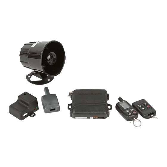
- Page 2 CA 170 SYSTEM LAYOUT...
-
Page 3: Programming Guide
CA170 - Programming Guide Feature Bank 1 - 3 Chirps Transmitter Programming Feature Bank 2 - 4 Chirps 1 LED Flash 2 LED Flashes 3 LED Flashes 4 LED Flashes 1. Siren/Horn Chirps Both On Siren Only Horn Only 2. Siren Output Steady 5 Sec. -
Page 4: Setup And Programming
Dome Light Delay/Theater Lighting Programming The CA 170 can be programed to delay arming after the lock button is pressed (60 second max) for vehicles with a dome light delay or theater dimming feature. Once programed the CA 170 will ‘learn’ the timing of the dome light delay and add 2 seconds before arming. - Page 5 SETUP & PROGRAMMING, CONTINUED Custom Pin Code Programming Programming your Pin Code (pin code must be two digits). Turn the ignition ON. Press and hold the programming button for 10 seconds, the system will chirp 3 times. Advance to Feature Bank 3, (5 chirps). Press and hold TRUNK button for three seconds to enter pin code programming, the siren will chirp twice and the LED will flash twice.
- Page 6 1. 5 PIN MAIN POWER HARNESS Parking Light Input (+/-) (WHITE/RED) Determine the vehicle's parking light polarity and connect this white as follows: Positive Polarity Systems: Connect the WHITE/RED wire to a fused constant (+) 12 volt supply. Negative Polarity Systems: Connect the WHITE/RED wire to chassis ground.
-
Page 7: Pin Input/Output Harness
1. 5 PIN MAIN POWER HARNESS, CONTINUED Battery Power (RED) Note: Remove the 3 Amp fuse until all connections are made. Locate 1 of the vehicle’s constant 12 Volt battery wires at the ignition switch. Verification: This wire will register voltage in all positions of the ignition switch. Connect the RED wire to the constant 12 Volt battery wire 2. - Page 8 2. 9 PIN INPUT/OUTPUT HARNESS, CONTINUED 12 volts Ignition Input (YELLOW) Locate the vehicle’s ignition wire at the ignition switch. Verification: This wire registers voltage when the key is turned to the ON (or RUN) position. The voltage does not drop out when the key is turned to the START (or CRANK) position. Connect the YELLOW wire to the vehicle’s Ignition wire.
-
Page 9: Door Locks
3. DOOR LOCKS Negative Lock Output / Positive Unlock Output (GREEN) Negative Unlock Output / Positive Lock Output (BLUE) Negative Second Door Unlock Output (Lt. GREEN/BLACK) The door lock / unlock outputs are designed to control several different types of systems which may require additional parts. - Page 10 3. DOOR LOCKS Negative Lock Output / Positive Unlock Output (GREEN) Negative Unlock Output / Positive Lock Output (BLUE) Negative Second Door Unlock Output (Lt. GREEN/BLACK) Positive Switching and Positive Switching with 2-step unlock feature: All Door Lock and Unlock: Locate the lock / unlock wire at the vehicle’s lock / unlock switch. Verification: These wires will register positive voltage when the Lock and Unlock switches are activated.
- Page 11 3. DOOR LOCKS Negative Lock Output / Positive Unlock Output (GREEN) Negative Unlock Output / Positive Lock Output (BLUE) Negative Second Door Unlock Output (Lt. GREEN/BLACK) Reverse Polarity (5-Wire Door locks) and Reverse Polarity with 2-step Unlock All Door Lock and Unlock: Locate the lock / unlock wire at the vehicle’s lock / unlock switch. Verification: These wires will rest at ground and register positive voltage when the Lock and Unlock switches are activated.
- Page 12 3. DOOR LOCKS Negative Lock Output / Positive Unlock Output (GREEN) Negative Unlock Output / Positive Lock Output (BLUE) Negative Second Door Unlock Output (Lt. GREEN/BLACK) One Wire Negative Multiplexed and One Wire Negative Multiplexed with 2-step Unlock Feature All Door Lock and Unlock: Locate the lock / unlock wire at the vehicle’s lock / unlock switch. Verification: This wire will show variable ground when the switch is activated.
- Page 13 3. DOOR LOCKS Negative Lock Output / Positive Unlock Output (GREEN) Negative Unlock Output / Positive Lock Output (BLUE) Negative Second Door Unlock Output (Lt. GREEN/BLACK) One Wire Positive Multiplexed and One Wire Multiplexed With 2-step Unlock Feature All Door Lock and Unlock: Locate the lock / unlock wire at the vehicle’s lock / unlock switch. Verification: This wire will show variable positive voltage when the switch is activated.
- Page 14 3. DOOR LOCKS Negative Lock Output / Positive Unlock Output (GREEN) Negative Unlock Output / Positive Lock Output (BLUE) Negative Second Door Unlock Output (Lt. GREEN/BLACK) Adding Aftermarket Actuators After installing aftermarket actuators (not supplied), connect the GREEN and BLUE wires shown in the diagram below using (2) SPDT relays (not supplied).
-
Page 15: Accessory Connectors
4 Pin Data Bus Interface Port: (Brown Connector) This 4 pin port is used for Code Alarm Door Lock and Transponder Databus Interfaces to communicate with the vehicle's Databus. When using the DBI port to control the Code Alarm Door Lock and Transponder Interface modules the following options may be available. -
Page 16: System Power-Up Procedure
5. SYSTEM POWER-UP PROCEDURE 1. After all connections are complete, turn the vehicle's ignition key to the ON position. 2. Insert both 3 Amp fuse into the fuse holder. 3. Turn the ignition key to the OFF position 6. MOUNTING THE MODULE / FINISHING THE INSTALLATION 1.
Need help?
Do you have a question about the CA 170 and is the answer not in the manual?
Questions and answers