
Related Manuals for Code Alarm ca 1151


Summary of Contents for Code Alarm ca 1151
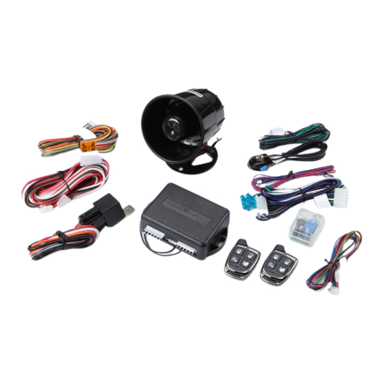
- Page 1 PROFESSIONAL SERIES Security and Keyless Entry Installation Guide ca 1151 ca1151 rev B. 2011 Audiovox Electronics Corporation. All rights reserved.
-
Page 2: Table Of Contents
Table of Contents Before You Begin ..................3 Wire Connection Guide ................4 6 Pin Main Harness ................... 5 6 Pin Input / Output Harness ..............6 3 Pin AUX Output Harness ............... 8 6 Pin Door Lock Output Harness ............. 9 Additional Ports .................. -
Page 3: Before You Begin
BEFORE YOU BEGIN PROFESSIONAL INSTALLATION STRONGLY RECOMMENDED Installation Precautions: Roll down window to avoid locking keys in vehicle during installation Avoid mounting components or routing wires near hot surfaces Avoid mounting components or routing wires near moving parts Tape or loom wires under hood for protection and appearance Use grommets when routing wires through metal surfaces... -
Page 4: Wire Connection Guide
6 Pin Main Harness 6 Pin Input / Output Harness 3 Pin AUX Output Harness 6 Pin Door Lock Output Harness ca1151 rev B. 2011 Audiovox Electronics Corporation. All rights reserved. -
Page 5: Pin Main Harness
6 Pin Main Harness WHITE PARKING LIGHT OUTPUT WHITE/RED PARKING LIGHT INPUT WHITE PARKING LIGHT OUTPUT Locate the parking light output wire at the vehicle’s light switch. Verification: This wire registers positive voltage when the parking lights are turned on. Positive switching Parking Lights: Connect the WHITE/RED wire to a 15 Amp max fused battery source. -
Page 6: Pin Input / Output Harness
BATTERY 12V ( + ) Locate 1 of the vehicle’s constant 12 Volt battery wires at the ignition switch. Verification: This wire will register ( + ) voltage in all positions of the ignition switch. Connect the RED wire to the constant 12 Volt battery wire. NOTE: Remove all fuses until all connections are made. - Page 7 GREEN DOOR TRIGGER INPUT ( - ) Locate the vehicle’s dome light or door pin switch wire. Verification: This wire will register ground (NEG) when the door is opened and the interior light is on. This wire will register positive voltage when the door is closed and the interior light is off.
-
Page 8: Pin Aux Output Harness
3 Pin AUX Output Harness VIOLET/BLACK AUX 1 OUTPUT ( - ) This wire provides a ( - ) 300mA output capable of driving relays. For Control of optional accessories (i.e. Power Window/Sunroof, etc.). To activate refer to the transmitter button configuration chart. Please refer to the selectable options for timing. -
Page 9: Pin Door Lock Output Harness
6 Pin Door Lock Output Harness BROWN/BLACK UNLOCK SWITCH ( 87A ) BLUE/BLACK UNLOCK MOTOR ( 30 ) VIOLET/BLACK UNLOCK POLARITY ( 87 ) WHITE/BLACK LOCK SWITCH ( 87A ) GREEN/BLACK LOCK MOTOR ( 30 ) VIOLET LOCK POLARITY ( 87 ) The door lock / unlock outputs are designed to control several different types of systems which may require additional parts. -
Page 10: Additional Ports
Additional Ports LED Port The LED included in the kit will serve as a visual indicator of the alarm’s status. It should be installed in the dash, located where it can be easily seen from outside the vehicle, yet not be distracting to the driver. Once a location has been selected, check behind the panel for wire routing access, and to confirm the drill will not damage any existing components as it passes through the panel. -
Page 11: Set Up & Programming
Set Up & Programming Transmitter Programming - Feature Bank 1 Turn the ignition ON. Press and hold the valet/override button. Within 10 seconds the system will chirp (3) three times. Press 1 button of each transmitter you wish to program. The system will respond with 1 chirp for each accepted transmitter. -
Page 12: Programming Feature Banks
Defaulting All Features: Pressing the button anytime while in any of the feature banks will default all features and return you to feature bank 2 - 4 chirps. NOTE: The system will remain in feature programming mode as long as the ignition is on, there is no time limit. -
Page 13: Adjusting The Shock Sensor
Adjusting the Shock Sensor Increase sensitivity by turning the adjustment dial clockwise. Decrease sensitivity by turning the adjustment dial counter clockwise. Testing the Shock Sensor Arm the system and wait 6 seconds for the zone to stabilize, then firmly strike the vehicles bumper. -
Page 14: Feature Descriptions
Feature Descriptions Feature Bank 2 - Security 1 - Silent Choice: Controls the normal arm/disarm chirps of the security system. ON - Silent arming/disarming upon first press of lock/unlock, pressing lock/ unlock a second time will activate the arm/disarm chirps respectively. The system will only sound the arm/disarm chirps upon a second press of the lock/unlock buttons. - Page 15 Feature Bank 3 - Output Control 1 - Extended Lock Pulse: Controls the timing of the BLUE and GREEN lock output wires. 1 Second - Single 1 second lock pulse, single 1 second unlock pulse. 3.5 Seconds - Single 3.5 second lock pulse, single 3.5 second unlock pulse. 1 Second Lock, Double Pulse Unlock - Single 1 second lock pulse, double 1 second unlock pulse.
-
Page 16: Transmitter Button Functions
5 - Horn Output Timing: Control the minimum horn pulse time in milli seconds, some vehicle will require a longer pulse to activate the factory horn. 16mS 10mS 30mS 40mS 50mS 6 - Real Panic: Controls the panic out when triggered from the transmitter. ON - Randomized horn honks when panic is triggered. -
Page 17: Security Trigger Zones
Security Trigger Zones If the security system has been triggered the LED will flash one of the patterns below indicating the zone. LED FLASHES TRIGGER ZONE 2 Flashes Hood / Trunk Input 3 Flashes Door Input 4 Flashes Shock Sensor 5 Flashes Ignition Input ca1151 rev B. -
Page 18: System Layout
ca1151 rev B. 2011 Audiovox Electronics Corporation. All rights reserved. - Page 19 ca1151 rev B. 2011 Audiovox Electronics Corporation. All rights reserved.
-
Page 20: Customer Service
Audiovox Electronics Corporation. Customer Service 1-800-421-3209 WWW.CODE-ALARM.COM FCC COMPLIANCE This device complies with Part 15 of the FCC rules and with RSS-210 of Industry Canada. Operation is subject to the following two conditions: 1. This device may not cause harmful interference, and 2.
Need help?
Do you have a question about the ca 1151 and is the answer not in the manual?
Questions and answers