Table of Contents
Advertisement
Quick Links
Advertisement
Table of Contents

Subscribe to Our Youtube Channel
Summary of Contents for Rockwell Automation SLC 500
-
Page 1: Power Supply
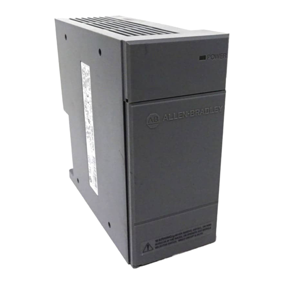
MANUFACTURER DATA SHEET Power Supply Manufacturer: Allen-Bradley/Rockwell Model Number: 1746-P1 See www.geomartin.com for additional PDF datasheets Martin Part Number: VendorPartNumber: E-014624-01 AB # 1746-P1, Power Supply PDF File: Doc_000005_Cover.pdf... - Page 2 This page is intentionally left blank...
-
Page 3: Slc 500™ Power Supplies
SLC 500™ Power Supplies (Catalog Numbers 1746-P1, 1746-P2, 1746-P3, 1746-P4, 1746-P5, 1746-P6, and 1746-P7) Installation Instructions Inside… page Overview ............1 Genéralités . -
Page 4: Important User Information
SLC 500™ Power Supplies Important User Information Because of the variety of uses for the products described in this publication, those responsible for the application and use of this control equipment must satisfy themselves that all necessary steps have been taken to assure that each application and use meets all performance and safety requirements, including any applicable laws, regulations, codes and standards. - Page 5 English Section SLC 500™ Power Supplies (Catalog Numbers 1746-P1, 1746-P2, 1746-P3, 1746-P4, 1746-P5, 1746-P6, and 1746-P7) Overview Install your power supply using these installation instructions. The only tools you require are Flat head (1/8”) and Phillips head (1/4”, #2) screwdrivers.
-
Page 6: Hazardous Location Considerations
SLC 500™ Power Supplies Hazardous Location Considerations This equipment is suitable for use in Class I, Division 2, Groups A, B, C, D or non-hazardous locations only. The following WARNING statement applies to use in hazardous locations. WARNING: EXPLOSION HAZARD •... -
Page 7: Install The Chassis Interconnect Cable (Optional)
SLC 500™ Power Supplies Install the Chassis Interconnect Cable (Optional) To connect up to three SLC 500™ chassis together, install the chassis interconnect cable before installing the power supply SLC 500 chassis/A For more information, see the SLC 500 Modular Style Installation and Operation Manual (publication 1747-6.2). -
Page 8: Power Supply Wiring
SLC 500™ Power Supplies Power Supply Wiring 1. Place the input voltage jumper to match the input voltage. (This does not apply to the 1746-P3, -P5, -P6, and -P7 power supplies, which do not have a jumper.) ATTENTION: Set the input jumper before applying power. - Page 9 DC NEUT Power CHASSIS GROUND ATTENTION: Your SLC 500 power supply can be damaged by voltage surges when switching inductive loads such as motors, motor starters, solenoids, and relays. To avoid damage to your SLC 500 power supply in these applications, it is strongly reccommended than an isolation transformer be used to isolate the power supply from harmful voltage surges.
- Page 10 SLC 500 Series A chassis (1746-A4, -A7, -A10, and -A13) with a manufacture date of November 1992 or later do not have this resistor. SLC 500 Series B chassis have a 1MΩ resistor that limits the current between logic ground and chassis ground.
- Page 11 SLC 500™ Power Supplies Processor SLC 500 Chassis 1746-P3 Door Not Used DH±485 Port Not Used SLC Logic +24V dc Resistor • DC Neut Chassis Chassis • Ground Earth Ground 4. (Optional) For the 1746-P1, -P2,-P4, -P5 and -P6 power supplies, use PWR OUT +24V dc and PWR OUT COM terminals to power 24V dc sensors and loads.
-
Page 12: Slc 500 Operation With 24V Dc User Power Overcurrent Condition
SLC 500™ Power Supplies SLC 500 Operation with 24V dc User Power Overcurrent Condition Catalog No. SLC Operation Recovery Procedure 1746-P1 Series A P/S shutdown, CPU Fault Reload user program (made in Japan) 1746-P1 Series A (made in Malaysia- 24V dc user shutdown, CPU continues... - Page 13 SLC 500™ Power Supplies Power Supply Undervoltage Operation SLC 500 controllers continue to operate (hold-up) for a short period of time if the input voltage to the power supply drops below the recommended operating voltage range. The controller continues to scan the user program and control I/O during this time.
- Page 14 SLC 500™ Power Supplies General Specifications (Power Supplies P1, P2, P3, and P4) See page 10 for general specifications on the P5, P6, and P7 power supplies. Specification: 1746- Description: 85-132/170-265V ac 85-132/170-265V Line Voltage 19.2-28.8V dc 47-63 Hz ac 47-63 Hz...
- Page 15 SLC 500™ Power Supplies General Specifications (continued) Specification: 1746- Description: Line Voltage 90-146V dc 30-60V dc 10-30V dc Typical Line Power 85 VA 100 VA 12V dc input: 50 VA 24V dc input: 75 VA Requirement Maximum Inrush 20A (required for turn-on)
-
Page 16: Physical Dimensions
SLC 500™ Power Supplies 24V dc 5V dc Output Current Output Current .87A 3.6A 0.625A 2.64A 0.46A 2.0A Input Voltage 10V dc 12.2V dc 19.2Vdc 30V dc 15Vdc Physical Dimensions Length: Depth: Height: Controller: 1746- mm (in.) mm (in.) mm (in.) 65 (2.56) - Page 17 Publication 1746-IN004A-ML-P - January 2000 40072-083-01 (A) Supersedes Publication 1746-5.1 - Oct 1999 2000 Rockwell International. All Rights Reserved. Printed in USA...
- Page 18 This page is intentionally left blank...


Need help?
Do you have a question about the SLC 500 and is the answer not in the manual?
Questions and answers