Table of Contents
Advertisement
Quick Links
Installation Instructions
Original Instructions
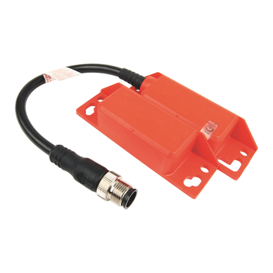
SensaGuard Rectangular Flat Pack (Series B Models Only)
Catalog Number 440N-Z21x
IMPORTANT
Save these instructions for future use.
Topic
Summary of Changes
This publication contains the following new or updated information. This list
includes substantive updates only and is not intended to reflect all changes.
Topic
Updated Certifications
Updated Maintenance
Updated Declaration of Conformity
Introduction
Installation must be in accordance with the following instructions and
specifications and implemented by suitable competent personnel. Adherence to
the recommended maintenance instructions forms part of the warranty.
Do not use this unit as a mechanical stop. You must fit guard stops and guides.
This device is intended to be part of the safety-related control system of a
machine. Before installation, you must perform a risk assessment to determine
whether the specifications of this device are suitable for all foreseeable
operational and environmental characteristics.
WARNING: Do not defeat, tamper, remove, or bypass this unit.
Severe injury to personnel can result.
Page
1
2
2
2
3
3
3
4
5
5
6
7
11
11
11
11
11
Page
2
11
11
ATTENTION: You must provide the device with a 24V DC PELV
or SELV power supply that conforms to the requirements of
414-3 of IEC 60364-4-41 where provisions are taken. The
voltage at the outgoing terminals cannot exceed 60V DC, even
if there is an internal fault.
Improper selection or installation of the devices affects the
integrity of the safety systems.
Personal injury or death, property damage, or economic loss
can result.
Comply with ISO 14119 including section, accessibility to the
installation, arrangement, and mounting, possible substitute
actuation, access to the escape release, motivation to defeat,
and actuation mode.
Use management controls, working procedures, training, and
additional protective measures to minimize the motivation to
defeat and to manage the use and availability of spare
actuators.
Comply with ISO 13857 and ISO 13855 for guard openings and
minimum (safe) distances.
Comply with EN ISO 13849-1, EN ISO 13849-2, and EN 61508 for
machinery and functional safety.
SensaGuard™ Series A and Series B non-contact switches only
work with the appropriate series actuator. Purchase Series A
and Series B actuators separately.
This product is intended for industrial/business application
only. This product is not intended for use in residential
applications, as it can cause radio interference on other
residential devices.
ATTENTION: Read this document and the documents that are
listed in
Additional Resources on page 11
Familiarize yourself with the installation and connection
instructions and requirements of all applicable codes, laws,
and standards.
In accordance with applicable codes of practice, suitably
trained personnel must implement installation, adjustments,
service initiation, use, assembly, disassembly, and
maintenance.
Use of this equipment not specified by the manufacturer can
impair the protection that the equipment provides.
ATTENTION: Do not attempt to install this device unless the
installation instructions have been studied and understood.
This document acts as a guide for a typical installation and is
available in additional languages at rok.auto/literature.
before you install.
Advertisement
Table of Contents

Related Manuals for Rockwell Automation Allen-Bradley SensaGuard 440N-Z21 Series


Summary of Contents for Rockwell Automation Allen-Bradley SensaGuard 440N-Z21 Series
-
Page 1: Table Of Contents
Installation Instructions Original Instructions SensaGuard Rectangular Flat Pack (Series B Models Only) Catalog Number 440N-Z21x ATTENTION: You must provide the device with a 24V DC PELV IMPORTANT Save these instructions for future use. or SELV power supply that conforms to the requirements of 414-3 of IEC 60364-4-41 where provisions are taken. -
Page 2: Specifications
• Overvoltage • Loss of ground Physical Characteristics Torque settings, max Switch/actuator mounting nut: 2.20 (19.5) Status Indicator [N•m (lb•in)] 13 mm (0.51 in.) for -CU models. The actuator is supplied with the sensor. Rockwell Automation Publication 440N-IN018D-EN-P - May 2023... -
Page 3: Diagnostics
OSSD 1 Input The recommended cable connection is 2 m (6.5 ft) (catalog number 889D-F8AB-2). For additional lengths, replace the 2 with 5 (5 m [16.4 ft]) or 10 (10 m [32.8 ft]). Rockwell Automation Publication 440N-IN018D-EN-P - May 2023... -
Page 4: Commissioning The Unique Coded Actuator
The Status/Diagnostic indicator flashes the number of actuators left that a sensor can learn. Red-red-red-green-green Actuator already learned. Red-red-red-green-green-green Bad RFID. Target moved out of range. Red-red-red-green-green-green-green Exceeded learning eight actuators. Red-red-red-green-green-green-green-green Unit locked. Cannot learn another actuator. Rockwell Automation Publication 440N-IN018D-EN-P - May 2023... -
Page 5: Ossd Test Pulses
Sensor 1 status indicator turns Sensor 2 status indicator turns green. Actuator 1 moves steady green. steady green. into sensing range. 0 ms 360 ms 378 ms 396 ms 0 ms 360 ms 378 ms 396 ms Rockwell Automation Publication 440N-IN018D-EN-P - May 2023... -
Page 6: Troubleshooting
Green status indicator is on. OSSDs de-energize to 0V. OSSDs de-energize to 0V. Green status indicator flashes to indicate Green status indicator flashes to indicate that OSSD inputs are not 24V. that OSSD inputs are not 24V. Rockwell Automation Publication 440N-IN018D-EN-P - May 2023... -
Page 7: Application Wiring Examples
Two Sensors in Series, Monitored Manual Reset Two Sensors and One 440L Safety Light Curtain in Series, Monitored Manual Reset IMPORTANT The safety light curtain must be last (farthest from the safety relay). Rockwell Automation Publication 440N-IN018D-EN-P - May 2023... - Page 8 +24V DC 889D-F5AC-5 Cordset Reset 889D-F5AC-5 Cordset Logic 440R-D22R2 S11 S21 Gate Gate K1 K2 Open Open 24V Ground +24V DC 889D-F5AC-5 Cordset Reset S11 S21 Reset 440R-S12R2 Gate K1 K2 Open 24V Ground Rockwell Automation Publication 440N-IN018D-EN-P - May 2023...
- Page 9 Figure 9 - CR30 Software Configurable Relay Wiring +24V DC 889D-F8AB-5 Cordset Safety Reset 889D-F5AC-5 Cordset 03 04 10 11 CR30 440C-CR30-22BBB 12 13 14 20 21 Gate Gate 100S Safety Contactor or Open Open 700S/700HPS Safety Relays 24V Ground Rockwell Automation Publication 440N-IN018D-EN-P - May 2023...
- Page 10 4 O0 4 I0 5 T0 871A-TS5-DM1 1+24 100S Safety Contactor or 1 T1 2 O1 700S/700HPS Safety Relays 2 I1 Safety Reset 4 O0 4 I0 5 T0 Power 24V Ground +24V DC Rockwell Automation Publication 440N-IN018D-EN-P - May 2023...
-
Page 11: Recommended Safety Control Interfaces
Figure 12 - Input and Output Configuration for the 1732ES Module Declaration of Conformity CE Conformity Rockwell Automation declares that the products that are shown in this document conform with the 2014/30/EU Electromagnetic Compatibility Directive (EMC) and 2006/42/EC Machinery Directive (MD) and that the respective standards and/or technical specifications have been applied. - Page 12 At the end of life, this equipment should be collected separately from any unsorted municipal waste. Rockwell Automation maintains current product environmental compliance information on its website at rok.auto/pec. Rockwell Otomasyon Ticaret A.Ş. Kar Plaza İş Merkezi E Blok Kat:6 34752 İçerenköy, İstanbul, Tel: +90 (216) 5698400 EEE Yönetmeliğine Uygundur Allen-Bradley, ArmorBlock, CompactBlock.
Need help?
Do you have a question about the Allen-Bradley SensaGuard 440N-Z21 Series and is the answer not in the manual?
Questions and answers