Table of Contents
Advertisement
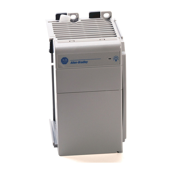
Compact I/O Expansion Power Supplies
Catalog Numbers 1769-PA2, 1769-PB2, 1769-PA4,
1769-PB4
Topic
About the Power Supplies
Compact I/O power supplies provide 120/240V AC and 24V DC power to modules, which
can be placed to the left or the right side of the 1769 power supply. As many as eight I/O
modules can be placed on each side of the power supply.
Installation Instructions
Page
2
3
4
4
5
6
9
11
14
15
17
18
19
19
21
24
25
28
30
35
Advertisement
Table of Contents

Related Manuals for Rockwell Automation 1769-PA2


Summary of Contents for Rockwell Automation 1769-PA2
-
Page 1: Table Of Contents
Installation Instructions Compact I/O Expansion Power Supplies Catalog Numbers 1769-PA2, 1769-PB2, 1769-PA4, 1769-PB4 Topic Page Important User Information Environment and Enclosure North American Hazardous Location Approval Install Safety Circuits European Hazardous Location Approval Before You Begin Assemble the System Mount an I/O Expansion Power Supply... -
Page 2: Important User Information
In no event will Rockwell Automation, Inc. be responsible or liable for indirect or consequential damages resulting from the use or application of this equipment. -
Page 3: Environment And Enclosure
Compact I/O Expansion Power Supplies Environment and Enclosure This equipment is intended for use in a Pollution Degree 2 industrial environment, in ATTENTION overvoltage Category II applications (as defined in IEC publication 60664-1), at altitudes up to 2000 meters (6562 ft) without derating. This equipment is considered Group 1, Class A industrial equipment according to IEC/CISPR Publication 11. -
Page 4: North American Hazardous Location Approval
Compact I/O Expansion Power Supplies North American Hazardous Location Approval The following information applies when Informations sur l’utilisation de cet operating this equipment in hazardous équipement en environnements dangereux: locations: Products marked "CL I, DIV 2, GP A, B, C, D" are suitable for use in Les produits marqués "CL I, DIV 2, GP A, B, C, D"... -
Page 5: European Hazardous Location Approval
Compact I/O Expansion Power Supplies European Hazardous Location Approval 1769-PB2, 1769-PB4 Only European Zone 2 Certification (The following applies when the product bears the Ex or EEx Marking) This equipment is intended for use in potentially explosive atmospheres as defined by European Union Directive 94/9/EC and has been found to comply with the Essential Health and Safety Requirements relating to the design and construction of Category 3 equipment intended for use in potentially explosive atmospheres, given in Annex II to this Directive. -
Page 6: Before You Begin
Compact I/O Expansion Power Supplies Before You Begin There are some points about power distribution that you should know. • The master control relay must be able to inhibit all machine motion by removing power to the machine I/O devices when the relay is de-energized. We recommend that the controller remains powered even when the master control relay is de-energized. - Page 7 Compact I/O Expansion Power Supplies Parts Illustration of a Power Supply The sample illustrations of a 1769-PA4 power supply let you review the various components that comprise a power supply, which is attached to a DIN rail. 44716 44718 1769-PA4 44719 44717 Item...
- Page 8 Compact I/O Expansion Power Supplies Item Description Upper tongue-and-groove slots Lower tongue-and-groove slots Upper DIN rail latches Lower DIN rail latches Terminal block with finger-safe cover Fuse housing cover for replaceable fuse 120V AC or 240V AC line input power selector switch (PA4 only) Removable selector switch label (PA4 only) Install an I/O Expansion Power Supply Compact I/O Expansion Power Supplies are suitable for use in an industrial environment...
-
Page 9: Assemble The System
Assemble the System 1769 Compact I/O power supplies distribute power from either side of the power supply. A 2 amp at 5V DC power supply (1769-PA2, 1769-PB2) can provide 1 amp to the right side EXAMPLE of the power supply and 1 amp to the left. A 4 amp at 5V DC power supply (1769-PA4, 1769-PB4) can provide 2 amps to the right side of the power supply and 2 amps to the left. - Page 10 Compact I/O Expansion Power Supplies Follow these steps to assemble the Compact I/O system. 1. Disconnect your line power. The power supply does not support removal or insertion of modules under power. If you connect or disconnect wiring while the field-side power is on, an electrical arc can WARNING occur.
-
Page 11: Mount An I/O Expansion Power Supply
Compact I/O Expansion Power Supplies Mount an I/O Expansion Power Supply During panel or DIN rail mounting of all devices, be sure that all debris (for example, ATTENTION metal chips, wire strands) is kept from falling into the module. Debris that falls into the module could cause damage on power up. - Page 12 Compact I/O Expansion Power Supplies Additional cooling provisions might be necessary when high ambient temperatures are encountered. Do not bring in unfiltered outside air. Place the Compact I/O system in an enclosure to protect it from a corrosive atmosphere. Harmful contaminants or dirt could cause improper operation or damage to components.
- Page 13 Compact I/O Expansion Power Supplies Mount a Power Supply on a DIN Rail The power supply can be mounted using the following DIN rails: • 35 x 7.5 mm (EN 50 022 - 35 x 7.5) • 35 x 15 mm (EN 50 022 - 35 x 15) 1.
-
Page 14: Verify Your System Power
• total 5V DC • total 24V DC • total 24V DC sensor power (1769-PA2 only) 3. If your power supply load is at or above the limits of the allowable ranges shown in the graphs, you must add an additional I/O bank. -
Page 15: Power Considerations
Compact I/O Expansion Power Supplies Power Considerations The following sections explain power considerations for the Compact I/O system. Disconnect the Main Power Explosion Hazard - Do not replace components or disconnect equipment unless power WARNING has been switched off. If you connect or disconnect wiring while the field-side power is on, an electrical arc can occur. - Page 16 Reload the user program following a power supply shutdown. To avoid unexpected operation due to 24V DC user power shutdown (1769-PA2 only), ATTENTION monitor the 24V DC user output with a 24V DC input channel.
-
Page 17: Use A Master Control Relay
Compact I/O Expansion Power Supplies Use a Master Control Relay A hard-wired master control relay (MCR) provides a reliable means for emergency machine shutdown. Since the master control relay allows the placement of several emergency-stop switches in different locations, its installation is important from a safety standpoint. Overtravel limit switches or mushroom-head push buttons are wired in series so that when any of them opens, the master control relay is de-energized. -
Page 18: Schematic (Using Iec Symbols)
Compact I/O Expansion Power Supplies Schematic (Using IEC Symbols) 230V AC Operation of either of these contacts will remove power from Disconnect the external I/O circuits, stopping Fuse machine motion. 230V AC Circuits Isolation Master Control Relay (MCR) Transformer Cat. No. 700-PK400A1 115V AC Emergency-Stop Suppressor... -
Page 19: Schematic (Using Ansi/Csa Symbols)
Compact I/O Expansion Power Supplies Schematic (Using ANSI/CSA Symbols) Operation of either of these 230V AC contacts will remove power from the external I/O circuits, stopping Disconnect machine motion. Fuse 230V AC Circuits Isolation Master Control Relay (MCR) Transformer Cat. No. 700-PK400A1 Emergency-Stop 115V AC Push Button... -
Page 20: Power Supply Connection
Compact I/O Expansion Power Supplies Each 1769 I/O module has a power supply distance rating, with a maximum value of eight. Refer to the specific 1769 I/O module’s installation instructions for more information. Power Supply Connection Bank 1 Bank 2 44723 Item Description... -
Page 21: Connect Field Wires
Compact I/O Expansion Power Supplies Connect Field Wires The following instructions explain how to wire your power supply. Ground the Power Supply This product is intended to be mounted to a well-grounded mounting surface such as a ATTENTION metal panel. Additional grounding connections from the power supply's mounting tabs or DIN rail (if used) are not required unless the mounting surface cannot be grounded. - Page 22 3. Connect incoming power to the power supply terminals as indicated below. Catalog Number 1769-PB2, 1769-PB4 NOT USED NOT USED +24V DC DC NEUTRAL CHASSIS GROUND Catalog Number 1769-PA2 Catalog Number 1769-PA4 PWR OUT +24V DC NOT USED NOT USED PWR OUT COM 120/240V AC (L1)
- Page 23 Compact I/O Expansion Power Supplies Wire the Finger-safe Terminal Block When wiring the terminal block, keep the finger-safe cover in place. 1. Loosen the terminal screws to be wired. Wiring the Finger-safe Terminal Block 2. Route the wire under the terminal pressure plate. You can use the bare wire or a spade lug.
-
Page 24: Replace The Fuse
Compact I/O Expansion Power Supplies Replace the Fuse Never install, remove, or wire power supplies unless power has been switched off. ATTENTION Follow these steps to replace a blown fuse. 1. Remove Compact I/O system power to correct conditions causing the short circuit. 2. -
Page 25: Temperature Derating
Compact I/O Expansion Power Supplies Temperature Derating The following graphs indicate how much current can be drawn from the power supply at the indicated case temperature without damaging it. 1769-PA2 Output Derating With User +24V Current Draw at 0 Amps 0.875 55 °C 60 °C... - Page 26 Compact I/O Expansion Power Supplies With User +24V Current Draw at 0.25 Amps 55 °C +24V Bus Load (Amps) 44728 1769-PB2 Output Derating Total Output: 29 W at 60 °C (140 °F) or below 60 °C +24V Bus Load (Amps) 44729 Publication 1769-IN028B-EN-P - October 2008...
- Page 27 Compact I/O Expansion Power Supplies 1769-PA4 Output Derating Total Output: 68 W at 55 °C (131 °F) or below 61 W at 60 °C (140 °F) or below 55 °C 60 °C +24V Bus Load (Amps) 1769-PB4 Output Derating Total Output: 68 W at 55 °C (131 °F) or below 61 W at 60 °C (140 °F) or below 55 °C 60 °C...
-
Page 28: Power Dissipation
Compact I/O Expansion Power Supplies Power Dissipation The following graphs indicate the real electrical power dissipation of the power supply in function of the electrical load. 1769-PA2 Real Power Dissipation 55 °C 60 °C Bus +5V, +24V, and User +24V Load... - Page 29 Compact I/O Expansion Power Supplies 1769-PA4 Real Power Dissipation 55 °C 60 °C Bus +5V, +24V, and User +24V Load (Watts) 1769-PB4 Real Power Dissipation 55 °C 60 °C Bus +5V, +24V, and User +24V Load (Watts) Publication 1769-IN028B-EN-P - October 2008...
-
Page 30: Specifications
Compact I/O Expansion Power Supplies Specifications 1769-PA2, 1769-PB2, 1769-PA4, 1769-PB4 - Technical Specifications Attribute 1769-PA2 1769-PB2 1769-PA4 1769-PB4 Input voltage range 85…265V AC 19.2…31.2V DC 85…132V AC or 19.2…32V DC 170…265V AC, switch selectable Input frequency 47…63 Hz 47…63 Hz... - Page 31 Compact I/O Expansion Power Supplies 1769-PA2, 1769-PB2, 1769-PA4, 1769-PB4 - Technical Specifications Attribute 1769-PA2 1769-PB2 1769-PA4 1769-PB4 Wire size 2.5 mm (14 AWG) solid copper wire rated at 90 °C (194 °F), or greater, 1.2 mm (3/64 in.) insulation max...
- Page 32 Compact I/O Expansion Power Supplies 1769-PA2, 1769-PB2, 1769-PA4, 1769-PB4 - Environmental Specifications Attribute 1769-PA2 1769-PB2 1769-PA4 1769-PB4 Vibration 5 g @ 10…500 Hz IEC 60068-2-6 (Test Fc, Operating) Operating shock DIN rail mount: 20 g; Panel Mount 30 g IEC 60068-2-27...
- Page 33 Compact I/O Expansion Power Supplies 1769-PA2, 1769-PB2, 1769-PA4, 1769-PB4 - Environmental Specifications Attribute 1769-PA2 1769-PB2 1769-PA4 1769-PB4 Conducted RF 10V rms with 1kHz sine-wave 80% AM from 150 kHz...80 MHz Immunity IEC61000-4-6 Voltage Variation 30% dips for 1 30% dips for 1 period at 0°...
- Page 34 Compact I/O Expansion Power Supplies 1769-PA2, 1769-PA4 - Certifications Value Certifications European Union 2004/108/EC EMC Directive, compliant with: • EN 61000-6-2; Industrial Immunity • EN 61000-6-4; Industrial Emissions C-Tick Australian Radio Communications Act, compliant with: • AS/NZS CISPR 11; Industrial Emissions When product is marked.
-
Page 35: Additional Resources
Compact I/O Expansion Power Supplies Additional Resources These documents contain additional information concerning related Rockwell Automation products. Resource Description 1769-ADN Adapter User Manual, publication A more detailed description of how to install and use a 1769-UM001 1769-ADN DeviceNet Adapter Module... -
Page 36: Installation Assistance
New Product Satisfaction Return Rockwell Automation tests all of its products to ensure that they are fully operational when shipped from the manufacturing facility. However, if your product is not functioning and needs to be returned, follow these procedures.
Need help?
Do you have a question about the 1769-PA2 and is the answer not in the manual?
Questions and answers