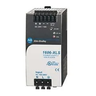
Rockwell Automation Allen-Bradley 1606 Series Reference Manual
Bulletin switched mode power supplies
Hide thumbs
Also See for Allen-Bradley 1606 Series:
- Reference manual (22 pages) ,
- Reference manual (14 pages)
Table of Contents
Advertisement
Quick Links
Reference Manual
Bulletin 1606 Switched Mode Power Supplies
Catalog Number: 1606-XLSBUFFER24
Index
1. Description .........................................,............................. 1
2. Specification Quick Reference ................................... 1
3. Catalog Numbers ............................................................. 1
4. Certification Marks ........................................................... 1
5. Standby Mode ................................................................. 4
.............................................................. 4
..................................................................... 5
Installation Notes
Mounting Orientation-The power terminal shall be located on top of the unit.
Cooling-Convection cooled, no forced air cooling required. Do not obstruct air flow!
Recommended Installation Clearances-40mm on top of unit; 20mm on bottom of unit; 0mm (or 15mm if adjacent device is a heat source) on
the left and right sides of the unit.
Intended Use-This buffer unit is designed for use in panel board installations or other in-building applications where a suitable mechanical
enclosure is provided to fulfil local requirements.
Service Parts-This unit does not contain any service part. Should damage or malfunction occur during installation, turn power off immediately and
return unit to the manufacturer for inspection.
...................................................... 6
................................ 6
...................................................... 7
11. Active and Ready Signal, Inhibit Input ............. 7
12. Terminals and Wiring ................................................ 8
13. Reliability .................................................................... 8
14. EMC ................................................................................ 9
............................................................. 9
17. Safety .......................................................................... 10
18. Certifications ............................................................. 10
.................................................. 12
............................................ 10
............... 11
Advertisement
Table of Contents

Summary of Contents for Rockwell Automation Allen-Bradley 1606 Series
-
Page 1: Table Of Contents
Reference Manual Bulletin 1606 Switched Mode Power Supplies Catalog Number: 1606-XLSBUFFER24 Index 1. Description .........,......1 11. Active and Ready Signal, Inhibit Input ..... 7 12. Terminals and Wiring ..........8 2. Specification Quick Reference ........1 3. Catalog Numbers ............. 1 13. -
Page 2: Description
Accessory 1606-XLB Wall mounting bracket UL 60950-1 EMC, LVD UL 508 GOST R C-Tick All parameters are specified at 24V, 20A, 25°C ambient and after a 5 minutes run-in time, unless noted otherwise. Rockwell Automation Publication 1606-RM026A-EN-P — April 2014... -
Page 3: Installation Requirements
Substitution of components may impair suitability for this environment. Do not disconnect the unit or operate the voltage adjustment or S/P jumper unless power has been switched off or the area is known to be non-hazardous. All parameters are specified at 24V, 20A, 25°C ambient and after a 5 minutes run-in time, unless noted otherwise. Rockwell Automation Publication 1606-RM026A-EN-P — April 2014... -
Page 4: Standby Mode
2) Re-charging is the charging of the internal capacitors after voltage interruptions of less than 2 minutes. Fig. 6-1 Re-charging time, 24V Charge 100% Charging Time All parameters are specified at 24V, 20A, 25°C ambient and after a 5 minutes run-in time, unless noted otherwise. Rockwell Automation Publication 1606-RM026A-EN-P — April 2014... -
Page 5: Buffer Mode
10,0 A 1,0 A 0,1 A 0,1 s 1,0 s 10,0 s 100,0 s All parameters are specified at 24V, 20A, 25°C ambient and after a 5 minutes run-in time, unless noted otherwise. Rockwell Automation Publication 1606-RM026A-EN-P — April 2014... -
Page 6: Functional Diagram
All parameters are specified at 24V, 20A, 25°C ambient and after a 5 minutes run-in time, unless noted otherwise. Rockwell Automation Publication 1606-RM026A-EN-P — April 2014... -
Page 7: Operating Diagram
500Vac Signal port to power port Wiring diagrams are provided in section 20. All parameters are specified at 24V, 20A, 25°C ambient and after a 5 minutes run-in time, unless noted otherwise. Rockwell Automation Publication 1606-RM026A-EN-P — April 2014... -
Page 8: Terminals And Wiring
It is the statistical representation of the likelihood of failure of a given device, and does not necessarily represent a life of a product. All parameters are specified at 24V, 20A, 25°C ambient and after a 5 minutes run-in time, unless noted otherwise. Rockwell Automation Publication 1606-RM026A-EN-P — April 2014... -
Page 9: Emc
Degree of pollution EN 50178, not conductive The ambient temperature is defined 2cm below the unit. All parameters are specified at 24V, 20A, 25°C ambient and after a 5 minutes run-in time, unless noted otherwise. Rockwell Automation Publication 1606-RM026A-EN-P — April 2014... -
Page 10: Protection Features
Product certification information (including Certificates and Declarations of Conformity) can be found at www.ab.com/certifications. All parameters are specified at 24V, 20A, 25°C ambient and after a 5 minutes run-in time, unless noted otherwise. Rockwell Automation Publication 1606-RM026A-EN-P — April 2014... -
Page 11: Physical Dimensions And Weight
Use DIN rails according to EN 60715 or EN 50022 with a height of 7.5 or 15mm Fig. 19-1 Side view Fig. 19-2 Front view Signal Connector All parameters are specified at 24V, 20A, 25°C ambient and after a 5 minutes run-in time, unless noted otherwise. Rockwell Automation Publication 1606-RM026A-EN-P — April 2014... -
Page 12: Wiring Diagrams
Buffer Unit Buffer Unit Supply Module Supply L N PE L N PE optional optional All parameters are specified at 24V, 20A, 25°C ambient and after a 5 minutes run-in time, unless noted otherwise. Rockwell Automation Publication 1606-RM026A-EN-P — April 2014... - Page 14 Rockwell Automation representative. New Product Satisfaction Return Rockwell Automation tests all of its products to help ensure that they are fully operational when shipped from the manufacturing facility. However, if your product is not functioning and needs to be returned, follow these procedures.


Need help?
Do you have a question about the Allen-Bradley 1606 Series and is the answer not in the manual?
Questions and answers