Table of Contents
Advertisement
Advertisement
Table of Contents

Related Manuals for Symbol ES3000


Summary of Contents for Symbol ES3000
- Page 1 ES3000 Ethernet Switch Advanced Concept Guide...
- Page 3 Advanced Concept Guide 72E-68445-01 Revision A May 2004...
- Page 4 Symbol reserves the right to make changes to any software or product to improve reliability, function, or design. Symbol does not assume any product liability arising out of, or in connection with, the application or use of any product, circuit, or application described herein.
-
Page 5: Table Of Contents
About This Guide Chapter 1. ES3000 Hardware Notes Hardware Notes ........... . 1-2 Chapter 2. - Page 6 Configuring and Monitoring Ports ........4-3 Symbol Access Port PoE Limits ....... . 4-4 Configuring the Switch Policy .
- Page 7 Spanning Tree Protocol (IEEE 802.1D) ........5-2 Configuring STP .
- Page 8 ES3000 Advanced Concept Guide Chapter 8. QOS Management QoS Overview ............8-2 QoS Markers.
- Page 9 Appendix A. Integrating with the Symbol WS 5000 WS 5000 Overview ..........A-2 Configuring for WS 5000 Integration .
- Page 10 ES3000 Advanced Concept Guide...
-
Page 11: About This Guide
About This Guide... -
Page 12: Notational Conventions
ES3000 Advanced Concept Guide Introduction The Advanced Concept Guide provides an introduction to the use of the ES3000 Ethernet Switch. This guide is aimed at network administrators who are experienced in configuring network devices or who want an introduction into some of the more advanced concepts involved in configuring Ethernet switches. -
Page 13: Chapter 1. Es3000 Hardware Notes
ES3000 Hardware Notes... -
Page 14: Hardware Notes
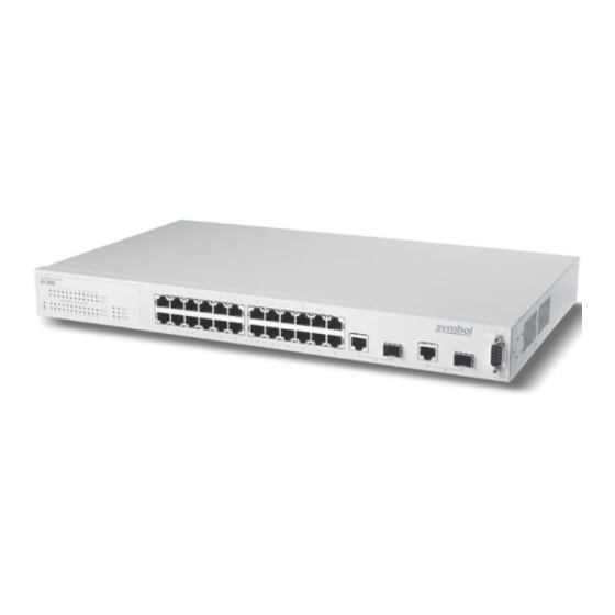
ES3000 Advanced Concept Guide 1.1 Hardware Notes The ES3000 Layer 2 Ethernet switch comes in two versions. One version provides power over Ethernet (PoE) in accordance with IEEE standard 802.3af. This allows compatible Ethernet devices to obtain power from the 10/100BaseT Ethernet wiring. The details of the PoE implementation are described Chapter 4, PoE Power Management. - Page 15 ES3000 Software Management...
-
Page 16: Initial Communication With The Switch
The only purpose of the IP address for the switch is to facilitate communication with the switch. The ES3000 switch defaults to DHCP for its IP address. If an installation requires that the switch have a fixed IP address, the IP address should be set using the serial interface. -
Page 17: Bootcode And Bootcode Prompt
2.3 Bootcode and Bootcode Prompt The software on the ES3000 switch is in two parts: the bootcode and the runtime code. The bootcode can only be updated through the serial interface to the switch. -
Page 18: Make The Bootcode Available
Symbol Technologies will make bootcode upgrades available through the Symbol support pages on the web and, if needed, through other means of distribution. The PoE version of the ES3000 and the non-PoE version of the ES3000 require, at this time, different versions of the bootcode. -
Page 19: Download The Bootcode File
[J]ump to Runtime Code Command> Enter “S” for “Software Upgrade”. 2.3.4 Download the Bootcode File The ES3000 will display the following: StrataSwitch II Series Boot System Version 1.0.0.0-012R / Apr 26 2004 11:44:48 Remote Server IP: 192.168.2.39 Remote File Name: ES3000_PWR_run_1-0-0-0-909R.rom... -
Page 20: Install The Bootcode
ES3000 Advanced Concept Guide >>> Software Upgrade Menu <<< Set Remote [S]erver IP Address Set Remote [F]ile Name [D]ownload software and Execute Download [B]ootcode and Execute Download [P]oL controller image [Q]uit to Previous Menu Command> Enter “S” for “Set Remote Server IP Address” and enter the IP address of the TFTP server. Enter “F”... -
Page 21: Runtime Software
After the runtime software is downloaded from Symbol Technologies, place the runtime software in the service directory for any TFTP server on the same LAN as the ES3000 switch. There are many TFTP servers available, some at no cost. The procedures in this section were tested using the Solar Winds TFTP server for Windows, available at www.solarwinds.net. -
Page 22: Resetting The Switch
2.5 Resetting the Switch If the password to the switch if lost or forgotten, the switch may be reset to the factory defaults, including the default password of “symbol” by the following: 1. Establish serial communication with the switch 2. Power cycle the switch 3. - Page 23 ES3000 Software Management Attaching SOC unit 0... GBP auto-sized to 16 MB, 4 banks, 64-bit bus MMU initialized. BCM driver initialized. ARL DMA shadowing enabled. Port modes initialized. MSR Task creation is successful CLI Task creation is successful Reset configuration to factory default ? ( y/n ) Afterwards, the system will reboot and will be available with the default passwords.
- Page 24 2-10 ES3000 Advanced Concept Guide...
-
Page 25: Chapter 3. Switch Management
Switch Management... -
Page 26: Managing The Switch
PoE power usage over threshold, or network topology changes, for example. In the ES3000 switch, the agent and the MIB reside on the switch. To configure SNMP on the switch, the administrator sets up the relationship between the agent and the SNMP managers. -
Page 27: Configuring Snmp Communication
The ES3000 switch also supports the Symbol-ES3000-MIB-06a MIB. This Symbol Technology proprietary MIB allows SNMP to be used to initiate the TFTP download of runtime firmware to the ES3000 switch and to initiate the uploading or downloading of ES3000 configuration files. 3.2.2 Configuring SNMP Communication To configure SNMP, the administrator sets up •... -
Page 28: Trap Receivers
ES3000 Advanced Concept Guide • Status: Enables or disables SNMP access for the community. The administrator can set the status to Enabled to allow access or Disabled to prevent access. • Privilege: An access privilege associated with the community/IP address pair. The administrator can select either Read-Only or Read-Write. -
Page 29: Port Counters
Switch Management • Bridge Topology Change: Generates a trap if switch-to-switch connections change. • Bridge New Root: Generates a trap if a topology change results in a new root switch. • RMON Alarm Trap: Generates a trap when a remote monitoring (RMON) alarm is triggered. -
Page 30: Configuration Files
If a large number of ES3000 switches must be configured, it may be worthwhile to manually configure one switch, examine the resulting configuration file, and use a scripting language to modify the switch to create near duplicates for configuration of the other switches. -
Page 31: Software Updates
Download button. 3.5 Software Updates Symbol periodically releases new versions of the software that runs on the switch. These software releases provide new features and functionality. To upgrade the switch to incorporate these changes, use the Software Upgrade page (System Admin. - Page 32 If the filenames are different, the switch will download the file identified by the filename in the DHCP information, load it, and reboot. If options 183 and 186 are set, ES3000 will download and use the configuration file specified in the DHCP information.
-
Page 33: Chapter 4. Poe Power Management
PoE Power Management... -
Page 34: Power Over Ethernet (Poe) Overview
4.2.1 Power Management Overview The ES3000 switch has a maximum PoE power budget of 170 watts. This is enough to supply 7 watts to all 24 PoE ports on the switch. The switch supplies a maximum of 16.5 watts per port. -
Page 35: Configuring And Monitoring Ports
Up. If PoE is Off, the display shows Down. The default is Up. • Status: The port’s power status. When a powered device is connected and enabled and the ES3000 is currently providing power, Powered is displayed. Otherwise, Not Powered is displayed. -
Page 36: Symbol Access Port Poe Limits
• Voltage (V): The voltage currently provided to the device in volts. • Current (A): The current currently provided to the device in amps. 4.2.2.1 Symbol Access Port PoE Limits The following table shows the Symbol recommended power limits for some typical Symbol Access Port configurations. Access Ports... -
Page 37: Symbol Recommendations For Power Policy
The default value is 80%. 4.2.4 Symbol Recommendations for Power Policy Symbol believes that most installations will be optimally served by the following power policy: • Set the power limit for the powered devices to the limits recommended in... -
Page 38: Troubleshooting
ES3000 Advanced Concept Guide • Use priority-based power management. • Either set the priority of currently unused ports to low and set the power budget for these ports to 16.5 watts. Under this policy, low-priority ports will be available as unmanaged powered ports. If there comes a time when there is insufficient power to supply all ports, the high-priority, managed, ports will receive power and some or all of the low-priority ports will not. -
Page 39: Chapter 5. Spanning Tree Protocols
Spanning Tree Protocols... -
Page 40: Spanning Tree Overview
ES3000 Advanced Concept Guide 5.1 Spanning Tree Overview The ES2000 switch can be configured to use one of three spanning tree protocols. Spanning Tree Protocol (STP) is compatible with legacy equipment. Rapid Spanning Tree Protocol (RSTP) is significantly faster than STP. Multiple Spanning Tree Protocol (MSTP) is based on RSTP and extends RSTP in a way that is useful for switches implementing VLANs. -
Page 41: Configuring Stp
Spanning Tree Protocols Root Switch Designated Port Designated Port Root Port Root Port Designated Switch Designated Switch Designated Port Designated Port Root Port Root Port Switch Designated Switch Designated Port Root Port Switch 5.3 Configuring STP MSTP is much faster than STP. STP is only at an advantage if there is legacy equipment in the network topology that does know how negotiate an MSTP cycle. -
Page 42: Refine Port Parameters
ES3000 Advanced Concept Guide 5.3.2 Refine Port Parameters When choosing a path from one switch to another, the spanning algorithm will: • Choose the port marked with the highest priority (lowest number) • If there is more than one port with the (same) highest priority, choose the port with the lowest cost •... -
Page 43: Multiple Spanning Tree Protocol (Ieee 802.1S)
Spanning Tree Protocols reconfiguration. Point-to-point link ports are ports that connect to another switch. Point-to-point links are reconfigured with a proposal-agreement dialog that is much faster than rebuilding the entire spanning tree. If an RSTP-enabled switch is connected to a switch that cannot communicate using RSTP BPDUs, the RSTP-enabled switch will communicate with the legacy switch using STP BPDUs. -
Page 44: Configuring Mstp And Cist
ES3000 Advanced Concept Guide 5.5 Configuring MSTP and CIST The process of configuring a switch for MSTP consists of the following steps: 1. Enable and define an MSTP configuration. 2. Set the timing parameters for the configuration. 3. If desired, define special tuning characteristics for the ports in the switch. - Page 45 Spanning Tree Protocols reduce the time that stations are unreachable when the spanning tree changes. Default: 20 seconds. • Forward Delay: How long a switch must listen for BPDU messages before making a reconfiguration choice. Longer intervals make certain that the switch has heard all possible messages but lengthen the time it takes to reconfigure the spanning tree on a topology change.
-
Page 46: Set The Port Characteristics
ES3000 Advanced Concept Guide 5.5.3 Set the Port Characteristics To speed the convergence of the spanning tree configuration or to push the spanning tree algorithm to make certain choices, the different ports characteristics can be tuned. The characteristics to be tuned are: •... -
Page 47: Make Vlan To Mstp Instance Assignments
Spanning Tree Protocols 5.5.4 Make VLAN to MSTP Instance Assignments MSTP spanning tree instances are identified by number, an integer between 2 and 64. Each VLAN can belong to exactly one MSTP instance. MSTP instances are created simply by assigning a VLAN to that instance number. -
Page 48: Static Forwarding Database
ES3000 Advanced Concept Guide 5.7 Static Forwarding Database For each VLAN, the ES3000 listens to the packets received at each port and maintains a list of MAC addresses from which packets have been received. This list of VLANs, ports, and MAC addresses is the forwarding database (FDB). -
Page 49: Chapter 6. Vlans
VLANs... -
Page 50: Vlan Overview
Virtual LANs (VLANs) are broadcast domains which are defined by the configuration of network equipment rather than cabling. The network administrator determines which end-stations are on which VLANs by software changes rather than cabling decisions. On the ES3000 switch, there are two kinds of VLANs: manual VLANs and dynamic VLANs. -
Page 51: Dynamic Vlans (Gvrp)
VLANs 6.1.2.1 Dynamic VLANs (GVRP) Other than allowing a port to be part of more than one VLAN, most of the advantages of tagged VLANs come from allowing the network equipment to configure the VLANs automatically. The VLANs configure themselves by exchanging GARP VLAN registration protocol (GVRP) messages. -
Page 52: Creating And Configuring A Vlan
ES3000 Advanced Concept Guide Switch A Switch B VLAN 10 VLAN 10 Switch B Switch D Switch C End-Station Switch C Switch D VLAN 10 VLAN 10 VLAN 10 A GVRP message can also start from an end-station with an 802.1Q-enabled network interface and will propagate in the same way as it would if the message had started with a switch instead of an end-station. - Page 53 VLANs • Tagged Members: Ports on the switch which must be part of the VLAN and which will receive tagged packets from the switch. • Untagged Members: Ports on the switch which must be part of the VLAN and which will receive untagged packets from the switch.
-
Page 54: Displaying And Modifying Vlan Information
ES3000 Advanced Concept Guide One and only one VLAN can also be marked as the Management VLAN. The default is VLAN 1, the VLAN which contains all ports. This default allows management access to the switch from all ports. If the Management VLAN is set to another VLAN, management of the switch will be restricted to ports on this VLAN. - Page 55 VLANs When a port number is selected, the information for that port is displayed. • Frame Type Acceptance: Admit All or Tagged Only. If Tagged Only, incoming packets which are not tagged with 802.1Q VLAN information will be dropped. If Admit All, then all packets will be admitted. •...
- Page 56 ES3000 Advanced Concept Guide...
-
Page 57: Chapter 7. Link Aggregation
Link Aggregation... -
Page 58: Link Aggregation Overview
7.2 Implementing Aggregate Links The ES3000 switch allows the administrator to create link aggregation groups that include up to eight physical ports in a single logical link. The administrator can define a maximum of six link aggregation groups. -
Page 59: Link Aggregation Mode
Link Aggregation For spanning tree protocol (STP), link aggregation groups function as a single virtual port. Any changes to one port in a group are applied to all ports in the group. 7.2.1 Link Aggregation Mode The LACP provides dynamic and static modes of link aggregation. The dynamic mode allows the switch to negotiate with partner interfaces to determine whether they can form a mutual link. -
Page 60: Modifying A Link Aggregation Group
ES3000 Advanced Concept Guide 7.2.2.2 Modifying a Link Aggregation Group On the Add Group page, the administrator can modify a link aggregation group in one of two ways: • By clicking the Modify button next to the group. When the Link Aggregation Modify page appears, the administrator can change the group mode and then either add or remove ports for the group. - Page 61 Link Aggregation...
- Page 62 ES3000 Advanced Concept Guide...
-
Page 63: Chapter 8. Qos Management
QOS Management... -
Page 64: Qos Overview
ES3000 Advanced Concept Guide 8.1 QoS Overview The ES3000 implements IEEE 802.1p Quality of Service (QoS) processing. QoS policies examine packets and classify them. The classification is used to drop packets or to remark packets. The possible markers are Class of Service (CoS) Priority, Type of Service (ToS) Precedence, and Differentiated Services Code Points (DSCP). -
Page 65: Creating A Qos Classifier
QOS Management • No-match actions act on packets that are in-bound to the switch and which do not match the characteristics specified by the classifier. Each of the components of a policy—classifier, action, port list—is identified by an index when it is created. -
Page 66: Creating A Qos In-Profile Action
ES3000 Advanced Concept Guide the destination IP address as 192.168.2.2 and the destination layer 4 port as 80, would apply only to port 80 traffic bound for that IP address. The format for the CLI command is diffserv classifier <id> [src-mac <MAC>][dst-mac <MAC>] [vlan-id <vid>] [dscp <value>][protocol <pro-num>]... - Page 67 The ToS Precedence and the lower three bits of the DSCP have no direct effect on the processing of the packet within the ES3000. They may be used by other QoS aware devices that transmit the packet.
-
Page 68: Creating A Qos Out-Profile Action
ES3000 Advanced Concept Guide In-profile actions can be created through the web interface (QoS > Policy Config. > Create In-Profile Action), the menu interface, or the command in the CLI. The format for the CLI diffserv inprofile command is: diffserv inprofile <id> {drop | dscp <value> | precedence <value>| cos <value>}... -
Page 69: Creating A Qos No-Match Action
QOS Management Out-profile actions can be created through the web interface (QoS > Policy Config. > Create Out- Profile Action), through the menu interface, or by using the command in the diffserv outprofile CLI. The format for the CLI command is: diffserv inprofile <id>... -
Page 70: Creating A Qos Port List
ES3000 Advanced Concept Guide No-match actions can be specified through the web interface (QoS > Policy Config. > Create No- Match Action) the menu interface, or the command in the CLI. The CLI command diffserv nomatch take the form: diffserv nomatch <id> {drop | dscp <value> | precedence <value> | cos <value>}... -
Page 71: Creating A Qos Policy
QOS Management 8.2.6 Creating a Qos Policy After all of the required classifiers and policies have been specified, a QoS policy can be created. The policy consists of a classifier, a sequence number, a port list, and one or more actions. The sequence number determines the order in which the policies are applied. -
Page 72: Displaying Qos Policies
8-10 ES3000 Advanced Concept Guide 8.3 Displaying QoS Policies After the QoS policies have been set, the policies which apply to a particular port can be displayed using the Policy Precedence display in the web interface (QoS > Policy Config. > Policy Precedence), menu interface, or the CLI command: show diffserv policy-precedence port <port num>... -
Page 73: Configuring Qos Queues
8-11 QOS Management 8.4 Configuring QoS Queues Each port has four output queues. The packets are sorted into the output queues depending on their CoS priority values. See Creating a QOS In-Profile Action on page 8-4 a discussion of CoS priority. The queues are serviced using a strict queuing algorithm. -
Page 74: Qos Configuration Example
8-12 ES3000 Advanced Concept Guide CoS priority values of 6 and 7 are usually reserved for control communication between network equipment. The mapping of CoS priority values to output queues can be changed using the Queue Mapping display (QoS > Queue Config. > Queue Mapping) or the command. -
Page 75: Port Numbers And Protocol Numbers
8-13 QOS Management The steps are given in CLI command: 1. Set up a classifier for a Ethernet Layer 4 destination port of 1071: diffserv classifier 101 dst-port 1071 2. Create an in-profile action which assigns a CoS priority level of 5: diffserv inprofile 201 cos 5 3. - Page 76 8-14 ES3000 Advanced Concept Guide Protocol Number IP Protocol IGMP: Internet Group Management Protocol TCP: Transmission Control Protocol UDP: User Datagram Protocol IPv6: Internet Protocol, version 6 RSVP: Reservation Protocol ISO-IP: ISO Internet Protocol A complete list of protocol numbers is available at http://www.iana.org/assignments/protocol-...
-
Page 77: Chapter 9. Port Security
Port Security... -
Page 78: Understanding 802.1X Port-Based Security
ES3000 Advanced Concept Guide 9.1 Understanding 802.1x Port-Based Security The ES3000 switch provides port-based security to prevent unauthorized clients from accessing a network. This security feature implements the IEEE 802.1x port-level authentication standard. Workstations (Clients) ES3000 Switch (Authenticator) Radius Server (Authentication Server) Figure 9.1 802.1x Device Roles... -
Page 79: Configuring Switch-To-Radius-Server Communication
Port Security 9.2 Configuring Switch-to-RADIUS-Server Communication Use the Radius Configuration page (Ports > Port Security > Radius) to configure RADIUS server parameters on the switch. This page includes the following parameters: • Server IP address: The IP address of the remote RADIUS server. •... - Page 80 ES3000 Advanced Concept Guide Unauthorized. The switch ignores all attempts by the client to authorize. • Auto: Enables 802.1x authentication, which causes the port to begin in the unauthorized state. In the unauthorized state, only EAP over LAN (EAPOL) frames are sent through the port until the RADIUS server authorizes the connection.
- Page 81 Port Security • Re-auth status: Enables or disables periodic re-authentication of a port. When this parameter is enabled, the switch re-authenticates the client at a periodic interval, as specified by the Re-auth Period parameter. The default is Disabled.
- Page 82 ES3000 Advanced Concept Guide...
-
Page 83: Chapter 10. Port Mirroring
Port Mirroring... -
Page 84: Port Mirroring Overview
ES3000 Advanced Concept Guide 10.1 Port Mirroring Overview Port mirroring allows one port on the ES3000 to see all of the packets passing through any other port on the switch. Usually, a network analyzer is attached to the monitoring port so the network administrator may debug problems with the monitored port. -
Page 85: Disabling Port Mirroring
10-3 Port Mirroring Monitoring can show all packets, inbound or outbound to the target port, or it can be limited to just one direction. Choose Direction: RX to see only inbound packets. Choose Direction: TX to see only outbound packets. Choose Direction: Both to see all packets, inbound or outbound, to the monitored port. - Page 86 10-4 ES3000 Advanced Concept Guide...
-
Page 87: Chapter 11. Rate Limiting
Rate Limiting... -
Page 88: Understanding Rate Limiting
ES3000 Advanced Concept Guide 11.1 Understanding Rate Limiting Rate limiting, or storm control, prevents ports on the ES3000 switch from being overwhelmed by a DLF, broadcast, or multicast packet storm. DLF is an abbreviation for Destination Lookup Failure. When a Level 2 Ethernet switch receives a packet for a MAC address which is not yet known to be reachable through particular port, the packet is copied or flooded to all of the ports on the switch (or VLAN). - Page 89 11-3 Rate Limiting The administrator must set a threshold value above 0 before the switch enables storm control for any type of traffic.
- Page 90 11-4 ES3000 Advanced Concept Guide...
-
Page 91: Chapter 12. Igmp Snooping
IGMP Snooping... -
Page 92: Overview Of Igmp Snooping
For further information about IP multicast and IGMP, refer to RFC 1112 and RFC 2236. The ES3000 switch can “snoop” this messaging protocol to keep track of multicast groups and to insure that multicast traffic is sent only to the appropriate ports within a VLAN. -
Page 93: Vlan Filtering
12-3 IGMP Snooping has not sent an IGMP report within the Host Port Age-Out time, the port is dropped from the multicast group. 12.2.2 VLAN filtering Use the VLAN Filter Table page (IGMP Snooping IGMP Snooping Config VLAN Filter Table) to selectively enable or disable IGMP snooping for specific VLANs. - Page 94 12-4 ES3000 Advanced Concept Guide...
- Page 95 Integrating with the Symbol WS 5000...
- Page 96 The WS 5000 directly supports four Access Port. Up to 30 Access Ports may be added by connection the WS 5000 to a Layer 2 Ethernet switch, such as the ES3000, and then connecting the Access Ports to the Layer 2 switch.
- Page 97 The WS 5000 and the Symbol Access Ports do not understand GVRP packets for dynamic VLAN creation, so they should be connected to ports on the ES3000 which are manually configured to be part of the correct VLAN and which are not enabled for GVRP.
- Page 98 If any of the Access Ports will be supporting any kind of streaming media, most likely VoIP, the WS 5000 and all of the ES3000 switches should be configured with a consistent QoS policy that supports that traffic. See the technical literature of the mobile units for the QoS requirements for that...
- Page 99 Customer Support...
- Page 100 ES3000 Advanced Concept Guide Symbol Technologies provides its customers with prompt and accurate customer support. Use the Symbol Support Center as the primary contact for any technical problem, question or support issue involving Symbol products. If the Symbol Customer Support specialists cannot solve a problem, access to all technical disciplines within Symbol becomes available for further assistance and support.
- Page 101 Web Support Sites MySymbolCare http://www.symbol.com/services/msc Symbol Services Homepage http://symbol.com/services Symbol Software Updates http://symbol.com/service/downloads Symbol Developer Program http://software.symbol.com/devzone Additional Information Obtain additional information by contacting Symbol at: 1-800-722-6234, inside North America +1-631-738-5200, in/outside North America http://www.symbol.com/...
- Page 102 ES3000 Advanced Concept Guide...
- Page 103 Glossary BPDU Bridge Protocol Data Unit CIST Common and Internal Spanning Tree Command Line Interface Class of Service Common Spanning Tree DHCP Dynamic Host Configuration Protocol Destination Lookup Failure DSCP Differentiated Services Code Points Extensible Authentication Protocol EAPOL EAP Over LAN Forwarding Database GARP Generic Attribute Registration Protocol...
- Page 104 GL-2 ES3000 Advanced Concept Guide Intermediate Distribution Frame IGMP Internet Group Management Protocol Internet Protocol LACP Link Aggregation Protocol Local Area Network Media Access Control Main Distribution Frame Management Information Base MSTP Multiple Spanning Tree Protocol Network Access Server Powered Device...
- Page 105 ......5-3, 5-6 address, Symbol....... B-2 timing parameters.
- Page 106 ....A-2 fax numbers, Symbol......B-2 RADIUS .
- Page 107 IN-3 overview......12-2 login procedure ....... 2-2 router reports .
- Page 108 IN-4 ES3000 Advanced Concept Guide lists........8-8...
- Page 109 IN-5 maximum for ports ......4-5 overview ....... . 4-2 RADIUS ports .
- Page 110 ........5-7 web sites, Symbol......B-2 STP .
- Page 111 Symbol Technologies, Inc. One Symbol Plaza Holtsville, New York 11742-1300 http://www.symbol.com 72E-68445-01 Revision A May 2004...
Need help?
Do you have a question about the ES3000 and is the answer not in the manual?
Questions and answers