Table of Contents
Advertisement
Installation Manual for the
ACCESS
SYSTEMS
PROFESSIONAL RESIDENTIAL
GPX-SL25
GPX-SL25
Slide Gate Operator System
PROFESSIONAL INSTALLATION RECOMMENDED!
WARNING!
This equipment is similar to other gate or door equipment and meets or
exceeds Underwriters Laboratory Standard 325 (UL 325). However, gate
equipment has hazards associated with its use and therefore by installing this
product the installer and user accept full responsibility for following and noting
the installation and safety instructions. Failure to follow installation and safety
instructions can result in hazards developing due to improper assembly. You
agree to properly install this product and that if you fail to do so Gates That
Open, LLC, ("GTO") shall in no event be liable for direct, indirect, incidental,
special or consequential damages or loss of profits whether based in contract
tort or any other legal theory during the course of the warranty or at any time
thereafter. The installer and/or user agree to assume responsibility for all
liability and use of this product releasing Gates That Open, LLC, from any
and all liability. If you are not in agreement with this disclaimer or do not feel
capable of properly following all installation and safety instructions you may
return this product for full replacement value.
READ ALL INSTRUCTIONS CAREFULLY AND COMPLETELY before
attempting to install and use this automatic gate operator. This gate operator
produces a high level of force. Stay clear of the unit while it is operating and
exercise caution at all times.
All automatic gate operators are intended for use on vehicular gates only.
DO NOT INSTALL THIS OPERATOR WITHOUT
SAFETY EDGES AND ROLLER GUARDS!
This product meets and exceeds the requirements of UL 325, the standard which
regulates gate operator safety, as established and made effective March 1, 2000,
by Underwriters Laboratories Inc.
®
, LLC
For more information on the GTO/ACCESS SYSTEMS full line of automatic gate
operators and access controls visit our website at www.gtoaccess.com.
©2012 Gates That Open, LLC
Printed in China for Gates That Open, LLC.
rev 03.21.13
Advertisement
Table of Contents

Related Manuals for GTO GPX-SL25


Summary of Contents for GTO GPX-SL25
- Page 1 Gates That Open, LLC, (“GTO”) shall in no event be liable for direct, indirect, incidental, special or consequential damages or loss of profits whether based in contract tort or any other legal theory during the course of the warranty or at any time thereafter.
-
Page 2: Class Rating
Please record the following information product serial number (located on right side of the operator housing), be sure to keep all receipts for proof of purchase. Refer to this information when calling GTO for service or assistance with your automatic gate opener. -
Page 3: Table Of Contents
Using The Mounting Template ...........................8 Installing The Chain ..............................9 Powering The System ............................10 Connecting The Battery ..........................10 Installation Of The Gto Transformer ..................... 10 Connecting Solar Panel(s))........................11 Connecting The Receiver ......................... 11 Control Board Settings ............................12 Dip Switches .............................. -
Page 4: Please Read This First
The GPX-SL25 operator is designed for installation on a slide-to-open single leaf gate. The gate must not exceed 24 feet in length nor weigh more than 650 pounds (please see Technical Specifications on page 2). The GPX-SL25 operator can be used on vinyl, aluminum, chain link and wrought iron gates. -
Page 5: Disconnecting The Operator
Because GTO automatic gate operators are only part of the total gate operating system, it is the responsibility of the installer/consumer to ensure that the total system is safe for its intended use. -
Page 6: Important Safety Instructions
5. Do not activate your gate operator unless you can see it and can determine that its area of travel is clear of people, pets, or other obstructions. Watch the gate through its entire movement. 6. Secure outdoor or easily accessed gate operator controls in order to prohibit unauthorized use of the gate. rev 03.21.13 GPX-SL25 Instruction Manual... -
Page 7: Required Safety Precautions For Gates
Should you lose or misplace this manual, a copy can be obtained by downloading one from the GTO web site (www.gtoaccess.com), by contacting Gates That Open, LLC., at 3121 Hartsfield Road, Tallahassee, Florida 32303 or by calling 1-800-543-4283 and requesting a duplicate copy. -
Page 8: Secondary Means Of Protection Against Entrapment
The GPX-SL25 utilizes Type A, an inherent (i.e., built-in) entrapment sensing system as the primary type of entrapment protection. Also, the GPX-SL25 has provisions for the connection of Type B1 or B2 protection to be used as the secondary type of entrapment protection, if desired. - Page 9 Entrapment Protection GTO’s internal obstruction settings, even when properly adjusted, may not be sensitive enough to prevent bodily injury. For this reason, safety devices such as safety edges MUST be installed. Furthermore, a pedestrian gate must be installed if walk-through traffic is expected near the gate.
- Page 10 1. Lift quick release pins UP , then pull them OUT of chain brackets. 2. Lay chain down and manually slide gate to desired position. Gates That Open, LLC. Tallahassee, Florida USA Product identification and manual operation instruction label installed on outer housing. rev 03.21.13 GPX-SL25 Instruction Manual...
-
Page 11: Before You Begin
• All low voltage wire used with the GTO Gate Operator must be 16 gauge dual conductor, stranded, direct burial wire [RB509]. Do not run more than 1000 ft. of wire. • Two GTO 12 volt batteries [RB500] are required for the GPX-SL25 to run on solar power. (see accessories on page 27) Solar Panel and Gate Activity Chart Estimated Maximum Number of Cycles Per Day... -
Page 12: Gpx-Sl25 Technical Specifications
• Temperature range -5 °F to +120 °F. An operation cycle is on * These specificaitons Gate Capacity Chart for GPX-SL25 Series full opening and closing are subject to change (estimated number of cycles based on use with a transformer) of the gate. -
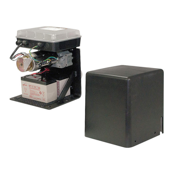
Page 13: Gpx-Sl25 Parts Identification
GPX-SL25 PARTS IDENTIFICATION Control Box with Control Board Operator Operator Housing 25’ Drive Chain (R4966) (R4487) (2) Chain Brackets (204IH) GTO Receiver (1) 12 Volt 7 amp GTO Transmitter (AQ202-NB) Battery 18 Vac Transformer (RB741) 120 Volt (RB570) (R4677) (3) 1/4”-20 x 1/2”... -
Page 14: Single Gate Operator Installation
The diagram below shows a single slide gate installation with required safety features. The operator must be installed on the inside of the gate. GTO requires using safety edges and roller guards to help reduce the possibility of bodily injury. -
Page 15: Determine Mounting Options
Adjustable galvanized pad mount adapter mounts the GPX- SL25 to an existing concrete pad or other mounting surfaces (See accessories on page 27). Pad Mount Adapter Plate can be adjusted from 6 inches to maximum height of 10 inches. Existing rev 03.21.13 GPX-SL25 Instruction Manual... -
Page 16: Determining Operator Mount Position
DETERMINING OPERATOR MOUNT POSITION Step 1 Be sure the gate is properly installed and slides smoothly before installing the GPX-SL25 . The gate must be plumb, level, and move freely. The gate must not bind or drag on the ground. - Page 17 Gate Support Gate Support Gate Support Gate Support Post Post 3” below the string. Post Post String String String String 13” 13” 13” 13” rev 03.21.13 GPX-SL25 Instruction Manual...
-
Page 18: Using The Mounting Template
Use at washers cover before installing as needed to to concrete pad level operator Use at washers as needed to level operator Concrete pad Existing Concrete pad Concrete pad rev 03.21.13 GPX-SL25 Instruction Manual... -
Page 19: Installing The Chain
Shorten chain by driving the pin out of the chain link Chain using a tool such as a punch or chain break. Connect Break the chain to the second quick release pin using a master link. Punch rev 03.21.13 GPX-SL25 Instruction Manual... -
Page 20: Powering The System
Connect the black battery lead to the negative (–) terminal, and the red battery lead to the positive (+) terminal. Installation of the GTO Transformer Choose the electrical outlet which the transformer will be plugged. Measure the distance from the electrical outlet to the control box, following the path where the low voltage wire will run using no more than 1000 ft. -
Page 21: Connecting Solar Panel(S))
Feed the receiver wires into the control box and attach them to the appropriate terminals on the control board (see illustration). Tighten set screws against exposed end of wires. Green Black Black (–) Receiver wire rev 03.21.13 GPX-SL25 Instruction Manual... -
Page 22: Control Board Settings
DIP switches OBSTRUCT SENS. GPX-SL25 series control board was configured for a single slide gate that opens right to left standing on the operator side of the gate. PULL/PUSH If your gate type matches this configuration, you DO NOT need to... - Page 23 All three potentiometers were set to minimum at the factory. The OBSTRUCT SENS. potentiometer MUST be adjusted above the factory setting for your GPX-SL25 operator to function properly. If the potentiometer is left at MIN, your gate operator may “obstruct”...
-
Page 24: Program Your Personal Transmitter
PROGRAM YOUR PERSONAL TRANSMITTER Program Your Personal Transmitter Setting All GTO transmitters are set to a standard code at the factory and are ready to operate your GTO gate operator. For your safety and security, we strongly recommend that you replace the factory setting with your own personal setting. -
Page 25: Mounting The Receiver
(see illustration). • Make sure antenna is higher than other metal objects. The receiver cable: • Cable length is 20 ft. (receivers with longer cables are available as special order items; call the GTO Sales Department). • NEVER splice receiver cable! • Run the receiver cable through PVC conduit to protect it from damage. • DO NOT run cable in conduit containing AC wiring. -
Page 26: Adjusting The Limit Switches
2. Gate Closing: For gate to close further, turn switches until desired limit is set. Limit Nut A counterclockwise. For gate to close less, turn Limit Nut A clockwise. Once the limit switches are adjusted, make sure the limit switch plate rests in the grooves on both limit nuts. Counter Clockwise Clockwise rev 03.21.13 GPX-SL25 Instruction Manual... -
Page 27: Connecting Safety Devices
CONNECTING SAFETY DEVICES The GPX-SL25 series operators are equipped with built-in obstruction detection. These operators are designed to stop and reverse the gate for 2 seconds when it comes in contact with an obstruction. Safety edges or photoelectric sensors MUST be installed on the gate. -
Page 28: Input Connections
• Activation of this input while gate is at the open limit will restart the auto close time (if enabled). WHT: (Typically used with doorbell button or hard wired key pad) • Each activation at this input will cycle the operation as follows ... X Open X STOP X CLOSE X STOP X OPEN X ... rev 03.21.13 GPX-SL25 Instruction Manual... -
Page 29: Connecting Accessories
Photo Beams (R4222) Vehicle Sensor (FM139) Refer to Vehicle Sensor manual for additional connections. Digital Keypad (F310) NOTE: There may be additional connection options for applications that are not illustrated here. Refer to accessory manuals for details. rev 03.21.13 GPX-SL25 Instruction Manual... -
Page 30: Dual Gate System Installation
60’ Power Cable (204IH) w/Strain Relief (R4677) (3) 1/4”-20 x 1/2” Nylon Thumb Screws (2) Chain Master Links (4) 3/8”-16 x 2” diameter U-Bolts and (8) 3/8” Serrated Nuts Zip Ties (2) Quick Release Pins rev 03.21.13 GPX-SL25 Instruction Manual... -
Page 31: Preparing The Gates
PREPARING THE GATES Install PVC conduit (not included) needed for power cables and low voltage wiring – see illustration below. The GPX-SL25 and GPX-SL252 power cable and safety edge (required) wiring should be run through PVC conduit underneath the driveway. Contact Sensor (REQUIRED) Roller Guard (REQUIRED) Receiver Contact Sensor Contact Sensor (cable in separate (REQUIRED) (REQUIRED) conduit) WARNING 120 Volt Indoor... -
Page 32: Wiring The Second Operator
Connect power cable wiring to second operator. Lock Nut Sealing Nut Step 2 Second Operator With the GPX-SL25 control box open, Power Cable remove a round knockout hole for First Operator power cable. Install the strain relief for the Second Operator power SEQ1 cable. Leave about 6” of the power... -
Page 33: Control Board Settings For Dual Install
18 Vac Transformer 18.0 to 22.0 Vac 10 W Solar panel (single) 18.0 to 22.0 Vdc In FULL SUN — measure voltage with the Solar Panel Disconnected. 12 V, 7 amp hour Battery 12.5 to 13.5 Vdc Measure voltage at battery terminals with battery disconnected Charging circuit 12.0 to 14.8 Vdc Measure voltage at battery terminals with battery connected rev 03.21.13 GPX-SL25 Instruction Manual... -
Page 34: Attaching The Housing
Slide operator housing over legs, align holes, and use screws provided to attach housing to operator. IMPORTANT: Hang the two (2) GTO Warning Signs (provided) on both sides of the gate before operating. Make sure all warning signs and labels are in place. -
Page 35: Warranty And Repair Service
2. Use the 24/7 Troubleshooting Wizard at http://support.gtoinc.com. 3. If you are unable to solve the problem, call the GTO Service Department at (800) 543-1236, or (850) 575-4144. Refer to the serial number (located on the right side of the control box) and date of purchase when calling for assistance. -
Page 36: Troubleshooting Guide
TROUBLESHOOTING GUIDE If your gate opener does not function properly, use this guide or use the online troubleshooter at http://support.gtoinc.com before calling the GTO Service Department. SYMPTOMS CAUSES CORRECTIVE ACTION • Check replace fuse(s) • Check battery connections at battery •... -
Page 37: Accessories
This specially designed wire is UV treated, PVC coated, and ready for direct burial. Solar Panel Kits [FM122/FM123] If your gate operator is more than 1000 ft. away from an AC power outlet, you can choose to maintain the battery charge with the GTO Solar Panel Kit. • 10 Watt Solar Panel Charging Kit [FM123] • 5 Watt Solar Panel Charging Kit [FM122] Replacement Battery [RB500] For replacement. - Page 38 100 ft. range between transmitter and receiver. Easy installation. LOCKING & SECURITY ACCESSORIES Pin Lock [FM345] The pin lock can be inserted in the chain bracket of the GPX-SL25 to prevent unauthorized removal of quick release pins. Wireless Driveway Alarm [R4450].
- Page 39 #41 Slide Gate Chain (R4487) The #41 chain (25’ only) is used with the GPX-SL25 / GPX-SL252 DC Slide Gate Operators. Post Mount Adapter Plate (R4983), (R4983 - 48) and (R4983 - 60) Galvanized post mount adapter is availible in 30, 48 and 60 inches in length.
- Page 40 ACCESS SYSTEMS PROFESSIONAL RESIDENTIAL 3121 Hartsfield Road • Tallahassee, Florida, USA 32303 (850) 575-0176 • Fax (850) 575-8912 Web site www.gtoaccess.com 24/7 Troubleshooting Wizard: http://support.gtoinc.com...
Need help?
Do you have a question about the GPX-SL25 and is the answer not in the manual?
Questions and answers