Table of Contents
Advertisement
O W N E R ' S M A N U A L
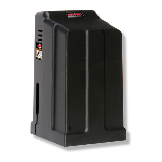
GP-SL100
Commercial Duty Slide Gate Operator
With Inherent UPS Battery Back-up System
TWO 12VDC, U1, 230A BATTERIES ARE REQUIRED BUT NOT INCLUDED.
DO NOT Install This Operator Without Roller Guards, Safety Edges and Photo Beams!
APPROPRIATE ENTRY/EXIT DEVICES WILL BE REQUIRED - SEE YOUR DEALER.
This product meets and exceeds the requirements of UL 325 gate operator safety standards.
US
For more information on GTO/PRO's full line of automatic gate openers and access controls visit our website at www.gtopro.com
Advertisement
Table of Contents

Subscribe to Our Youtube Channel
Related Manuals for GTO GP-SL100


Summary of Contents for GTO GP-SL100
- Page 1 APPROPRIATE ENTRY/EXIT DEVICES WILL BE REQUIRED - SEE YOUR DEALER. This product meets and exceeds the requirements of UL 325 gate operator safety standards. For more information on GTO/PRO’s full line of automatic gate openers and access controls visit our website at www.gtopro.com...
- Page 2 • This gate operator may produce a high level of force. Stay clear of the unit while it is operating and exercise caution at all times. the gp-sl100 automatic gate operators are intended for use with vehicular slide gates. the operators can be used in class i, ii, iii, and iv applications. vehicular gate operator class categories residential vehicular gate operator–class i: A vehicular gate operator (or system) intended for use...
-
Page 3: Table Of Contents
Table of Contents Gate Operator Class Categories ...Inside Cover Metric Conversion Chart ...Inside Cover Safety Instructions for the GP-SL100 Slide Gate Operators ...1 Important Safety Instructions for the System Designer...1 Important Safety Instructions for the Installer ...2 Important Safety Instructions Specific to Secondary Means of Protection Against Entrapment ...3 Important Safety Instructions for the Consumer/End User ...4 Required Safety Precautions for Gates ...5 Warning Labels ...6 Technical Specifications ...7 Parts Identification ...8 Installing the Gate Operator ...9 Preparation of the Gate ...9 Operator Installation Overview ...9 Using the Mounting Template ... 10 Mounting Template (not to scale) ... 11 Removing the Operator Housing ... -
Page 4: Safety Instructions For The Gp-Sl100 Slide Gate Operators
Because gto automatic gate operators are only part of the total gate operating system, it is the responsibility of the designer, installer, and purchaser to ensure the total system is safe for its intended use. Bypassing safety devices or neglecting to use safety devices with the gate operator is Not acceptable. -
Page 5: Important Safety Instructions For The Installer
Important Safety Instructions ImPOrtant Safety InStrUCtIOnS For the Installer WarNiNg–to reduce the risk of injury or death: i. Before installation reaD aND FolloW all iNstructioNs. 2. Verify this operator is proper for the type and size of gate, and its frequency of use. Make sure that the gate has been properly installed and slides freely in both directions. Repair or replace all worn or damaged gate hardware prior to installation. A freely moving gate will require less force to operate and will enhance the performance of the operator and safety devices used with the system. -
Page 6: Important Safety Instructions Specific To Secondary Means Of Protection Against Entrapment
An automatic closing device (timer, loop sensor, etc.) shall not be employed. D. No other activation device shall be connected. The GP-SL100 operators are designed to stop and reverse for 2 seconds when the gate comes in contact with an obstruction or when an object activates the non-contact sensors. Additionally, these operators are equipped with an audio entrapment alarm which will function if the unit obstructs twice while opening or closing. -
Page 7: Important Safety Instructions For The Consumer/End User
If your gate has open rollers, be sure that roller guards have been installed to prevent hands and fingers from being caught in the rollers (see page 5). It is your responsibility to make sure that the installer posted warning signs on both sides of your gate. If any of these signs or warning decals become damaged, illegible or missing, replace them immediately. Contact your installer or GTO for replacements. 10. Verify that electric safety edge sensors or photoelectric sensors have been installed (see page 5). These safety devices should be tested monthly. 11. KEEP GATES PROPERLY MAINTAINED. Have a qualified service person make repairs to the gate hardware. -
Page 8: Required Safety Precautions For Gates
Safety Edge Roller guard to prevent pinch point hazard. Safety Edge Roller guard to prevent pinch point hazard. Entrapment Protection GTO’s internal obstruction settings, even when properly adjusted, may not be sensitive enough to prevent bodily injury. For this reason, safety devices such as safety edges and photo beams MUST be installed. Furthermore, a walk-through gate must be installed if pedestrian traffic is expected near the gate. We recommend the GTO Bulldog Pedestrian Gate Lock (available as an accessory) for controlled access. Pedestrian Gate Screen Mesh Safety Edge... -
Page 9: Warning Labels
2. Disconnect chain from gate brackets. 3. Pull opener open. Disconnect operator ONLY when the power switch is OFF and the gate is NOT moving. GTO, Inc. Tallahassee, Florida USA Product identi cation and manual operation instruction label installed on cover. -
Page 10: Technical Specifications
Absolute minimum depth 18 in (45.7 cm) below ground level. Operational Temperature: • In colder climates (ambient temperatures less than 10 degrees) GTO recommends the use of a thermostatically controlled heating source (ceramic heating strips, etc.) on the batteries and gearbox assembly. Styles, types, and power requirements of heating devices will vary by climate and region. -
Page 11: Parts Identification
Fully Assembled Operator 13 in (33 cm) 27 in (68.6 cm) 18 in (46 cm) NOTE: GTO receiver (RB709U), batteries (12vdc, U1, 230A minimum) not included. Must order separately. Chain Brackets (2) Internal Operator Chassis 17 in (42 cm) 23¾ in (60.3 cm) -
Page 12: Installing The Gate Operator
Installing the Gate Operator this unit must only be installed by an experienced technician. preparation of the gate Before installing the GTO/PRO slide gate operator, make sure: • the gate is properly installed. • the gate is plumb, level, and moves freely. • the gate does not bind or drag on the ground. • the gate is screened if necessary (see page 5.) • roller guards are installed (see page 5.) overview of a single gate operator installation The diagram below is an example of a single slide gate installation with required safety features. -
Page 13: Using The Mounting Template
Using the Mounting Template The mounting template (see insert) is designed to simplify mounting the operator. It provides the installer with the proper locations for running power and accessory wiring conduits. The template is also marked with the correct distance between the operator mounting holes and shows the installer how to position the operator for the correct clearance between the housing and the gate. -
Page 14: Mounting Template (Not To Scale)
Mounting Template (NOT TO SCALE) -
Page 15: Removing The Operator Housing
Removing the Operator Housing Before you can gain access to the operator frame and its mounting holes, the housing will have to be removed from the operator. 1. Remove the (2) 3/8” allen bolts and (2) m8 washers from the operator housing (this hardware is located on each side of the housing). Lift the housing off the operator and set it aside. Mounting the Operator Lift the operator and align its mounting holes over the 3/8”... -
Page 16: Installing The Chain
Connect batteries to operator as shown. The red wire connects to the positive terminal in the control box. The black wire connects to the negative terminal in the control box. The jumper wire (included) connects both batteries together with the remaining terminals. Wire the 24V system in series as shown below. - Page 17 (included), as shown. Do not overtighten the nuts; they will be used to adjust chain tension. Pull the gate to the desired open position. Attach chain to one chain adjuster bolt. Use #41 chain with the GP-SL100. Thread chain through chain sprockets. Attach chain to second chain adjuster bolt. Allow a minimum of 1 inch slack in chain for every 10 feet of gate.
-
Page 18: Control Board Description
CLOSE <<< STOP CUT TO USE 3 BUTTON TEST SWITCHES STATION CLOSE GTO Inc. Tallahassee, FL SX4000 Logic Board Rev. E leD indicator - To Show ‘Running’ Relay is on leD indicator - To Show ‘Lock’ Relay is on leD indicators - To Show Dual Link Communication test switches - To Control Gate Operation limit adjustment control switches left and right stall Force adjustment auto close timers adjustment potentiometer (OFF, 3-120 sec) -
Page 19: Setting The Limits
RUN 2 OPEN CLOSE STOP GTO Inc. Tallahassee, FL SX4000 Logic Board Rev. E NOTE: Refer back to Step 4 under “Installing the Chain” pg.13 for setting the open limit. button on the board and be prepared to press the set liMit is on. -
Page 20: Stall Force And Auto-Close Adjustments
Stall force and auto-Close adjustments stall Force adjustment: IMPORTANT: For safety reasons, the at the factory. The obstruction sensitivity is independently adjustable for each direction of travel. Upon sensing an obstruction, the gate will stop and reverse direction for approximately 2 seconds. 1. Turning the potentiometer clockwise (toward the MAX position) increases the amount of force the operator applies to an obstruction. -
Page 21: Dip Switch Settings
• Dual Link cable is connected. • The second operator is detected by the master. • If the above conditions are not met, the board will default to EXIT single mode operation. If DIP #3 is OFF (Master) GTO LOOP DETECTORS ALARM • OFF: Master mode operation in dual gate installation if slave setting is detected from the other board. • ON: Slave mode operation in dual gate installation if master setting is detected from the other board. Control board is non- + ACC. PWR. functional if master operator is not detected. -
Page 22: Input Connections
Circuit common (reference for all logic input) • Three (3) terminals to provide extra common connection point. terminal. LOCK N.C. LOCK LOCK COM LOCK N.O. RUNNIN RUN 1 RUN 2 CLOSED CLOSED 1 CLOSED 2 CYCLE SAFETY SHADOW LOOP OPEN EDGE CLOSE EDGE OPEN CLOSE STOP GTO Inc SX4000 L... -
Page 23: Accessory Terminal Connections
According to Application V – LOOP LOOP GTO Loop Detector LOOP Siren-Activated Entry Device Cannot be mounted inside operator housing. GTO Universal Receiver Edge Sensor NOTE: Connections are for typical applications. -
Page 24: Output Connections
Output Connections Note: • Maximum rating for all relay outputs are 24Vac/dc, 1 Amp. • All relay outputs are dry contact (no voltage) switching. • All outputs have corresponding LED indicator for diagnostic purposes. The corresponding LED indicator will be lit when its relay is activated. closeD 1 closeD 2: At closed limit relay output. • These two (2) terminals are shorted when gate is at the closed limit. ruN 1 2: Gate moving relay output. • These two (2) terminals are shorted whenever the gate is moving/running. locK coM locK N.o. -
Page 25: Accessory Power Supply
12Vdc @ 300 mA (.3A) maximum power supply for additional accessories. • If you lose power to your accessories, the accessories are protected by a poly-fuse. Disconnect accessories and allow poly-fuse to cool down for 2 minutes before reconnecting. 12Vdc @ 300 mA Power Supply EXIT SHADOW GTO LOOP DETECTORS ALARM +12Vdc + ACC. PWR. 12VDC - 300ma DUAL DUAL LINK LINK LINK COM... -
Page 26: Prison Mode Operation And Wiring A 3-Button Station
EDGE CUT TO USE CUT TO USE 3 BUTTON 3 BUTTON CLOSE STATION STATION EDGE GTO Inc. Tallahassee, FL SX4000 Logic Board Rev. E OPEN CLOSE STOP CUT TO USE 3 BUTTON STATION Wiring a 3-button station NOTE: The W1 Jumper must be cut in order to use a 3-button station. -
Page 27: Reinstalling The Operator Housing
Reinstalling the Operator Housing Check to make sure the roller guards, fence screen, safety edges (or photoelectric beams), warning signs, and pedestrian gate (if necessary) are installed (see pages 5-6) before fastening the housing to the operator. Also, verify that the chain is properly aligned and not kinked or binding along its path of travel. lower the operator housing into position over the operator. -
Page 28: Installing A Dual System
Installing a Dual Gate Operator System IMPORTANT: With a dual gate system certain control board settings and connections are required on the MASTER unit only and some are required on both the MASTER and the SLAVE unit. The list below gives an overview. gate sequencing - DIP #2 on Master Unit •... -
Page 29: Setting Dual Gate Sequence
Setting Dual Gate Sequence GP-SL100 operators come from the factory with the #2 DIP switches set to OFF. Dip switches must be changed to accommodate dual gate operation. The information below shows the proper settings for a dual gate application. <<< >>> SIMUL DELAY SLAVE MASTER SECURE SAFE STALL FORCE ADJUST <<< >>> Master DIP Switch Settings IMPORTANT: The #2 Switch Settings are set on the MASTER Operator only. -
Page 31: Maintenance
Maintenance WARNING: ALWAYS TURN OPERATOR OFF AND DISCONNECT AC POWER BEFORE ADJUSTING OR SERVICING IT. Maintenance Schedule: • Test the operator, accessories, and safety devices monthly. • Service the gate operator, accessories, and safety devices regularly. Maintenance Checklist • Test the safety edges to make sure the gate responds. • Check the obstruction settings (both open and close modes) see page 17. • Oil and adjust the chain when necessary. • Check for wear on all moving parts, and tighten bolts as necessary. • Check the gearbox for any sign of oil leakage. If the gearbox is leaking, call the GTO Service Department for assistance. • Check rollers or hinges on the gate and lubricate if needed. • Check for loose or corroded wires. • Make sure the warning signs, roller guards, fence screen, etc. (see page 5) are installed. -
Page 32: Troubleshooting Guide
TroubleShooting Guide WARNING: ALWAYS TURN OPERATOR OFF AND DISCONNECT GP-SL100 Audible Feedback S Y M P T O M D I A G N O S I S One beep every 5 seconds There is no AC power present. when the gate is in motion. - Page 33 GP-SL100 Visual Feedback S Y M P T O M D I A G N O S I S cycle leD oN brightly Cycle terminal shorted to Com Status Light flashes safety leD oN Safety terminal shorted to Com brightly Status Light...
- Page 34 S Y M P T O M D I A G N O S I S close edge leD oN Close Edge terminal shorted to brightly Status Light flashes open leD oN brightly Open terminal shorted to Com Status Light flashes close leD oN brightly Close terminal shorted to Com Status Light flashes stop leD oN brightly Stop and Com terminals open.
-
Page 35: Warranty And Repair Service
Please retain these records. After the warranty period, GTO or one of its authorized service centers will make any necessary repairs for a nominal fee. Call GTO at (850) 575-0176 for more information. -
Page 36: Installation Checklist
____ The iMportaNt saFetY iNstructioNs manual was given to the customer. ____ Customer was instructed about proper use of the chain release pins. ____ Customer was asked to fill out customer support card and mail it to GTO, Inc. ____ Customer was asked to retain all receipts (receipts provide proof of warranty). ____ Customer was asked to retain iMportaNt saFetY iNstructioNs, etc. for future reference.
Need help?
Do you have a question about the GP-SL100 and is the answer not in the manual?
Questions and answers