Table of Contents
Advertisement
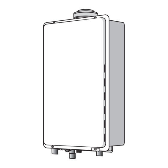
Installation Manual
To suit models:
Rinnai Infinity VT16
Rinnai Infinity VT20
Rinnai Infinity VT24
Rinnai Infinity VT26
Rinnai Infinity VTa26
i = internal
a = aggressive water
Models are not suitable as a spa or swimming pool heater.
Internal Rinnai continuous flow internal water heaters ('i' models) must be installed with an
approved Rinnai flue system.
Appliance must be installed, commissioned and serviced by a licensed tradesperson in
accordance with these instructions and all applicable local rules and regulations.
Your Rinnai continuous flow water heater complies with NZS 5262. A declaration to this effect
can be found on the Energy Safety web site; www.energysafety.govt.nz.
Continuous Flow Water
Heaters
REU-VR1620WG
Rinnai Infinity HD200
REU-VR2024WG
Rinnai Infinity HDi200
REU-VR2426WG
Rinnai Infinity HD250
REU-VR2626WG
Rinnai Infinity EF24
REU-VR2626WGT
Rinnai Infinity EF250
Rinnai Infinity EFi250
REU-VRM2632WC
REU-VR2632FFUG
REU-VR3237WG
REU-K2430WG
REU-KM3237WD
REU-KM3237FFUD
Advertisement
Table of Contents


Need help?
Do you have a question about the Infinity VT16 REU-VR1620WG and is the answer not in the manual?
Questions and answers
Hello do I have to light a pilot flame to get started
The installation manual does not mention the need to light a pilot flame to start the Rinnai Infinity VT16 REU-VR1620WG. Continuous flow water heaters like this model typically use electronic ignition, meaning they do not require a standing pilot flame.
This answer is automatically generated