Table of Contents
Troubleshooting

Subscribe to Our Youtube Channel
Related Manuals for Jet JWP-16OS


Summary of Contents for Jet JWP-16OS
- Page 1 OWNER’S MANUAL JWP-16OS Woodworking Planer WMH Tool Group Consumer Woodworking Division 2420 Vantage Drive Elgin, IL 60123 Ph: 888-594-5866 ▪ Fax: 800-626-9676 M-708531 Rev A 10/03 www.wmhtoolgroup.com Copyright © WMH Tool Group...
-
Page 2: Limited Warranty
This manual has been prepared for the owner and operators of a JET Model JWP-16OS Planer. Its purpose, aside from proper machine operation, is to promote safety through the use of accepted operating and maintenance procedures. Completely read the safety and maintenance instructions before operating or servicing the machine. -
Page 3: Table Of Contents
Optional Accessories ... 24 Troubleshooting ... 25 Performance Troubleshooting ... 25 Mechanical Troubleshooting ... 26 Parts List for the JWP-16OS Planer ... 27 Head Assembly ... 27 Head Assembly Parts List ... 28 Base Assembly... 30 Base Assembly Parts List... 30 Gear Box Assembly... - Page 4 Stand Assembly... 34 Stand Assembly Parts List ... 34 Electrical Schematic for JWP-16OS Planer ... 35...
-
Page 5: Warning
1. Read the manual. Always read the owner’s manual carefully before attempting to use the machine. Know the limitations and hazards associated with the use of this planer. 2. Installation. If mounting machine to the floor, use high quality anchor bolts through the mounting holes on the base. -
Page 6: Safety Decals
This means that if precautions are not heeded, it may result in minor or moderate injury and/or possible machine damage. Safety Decals Familiarize yourself with the location and content of these decals on your planer. 1. Read instruction manual before operating machine. 2. Do not operate without all guards properly installed. -
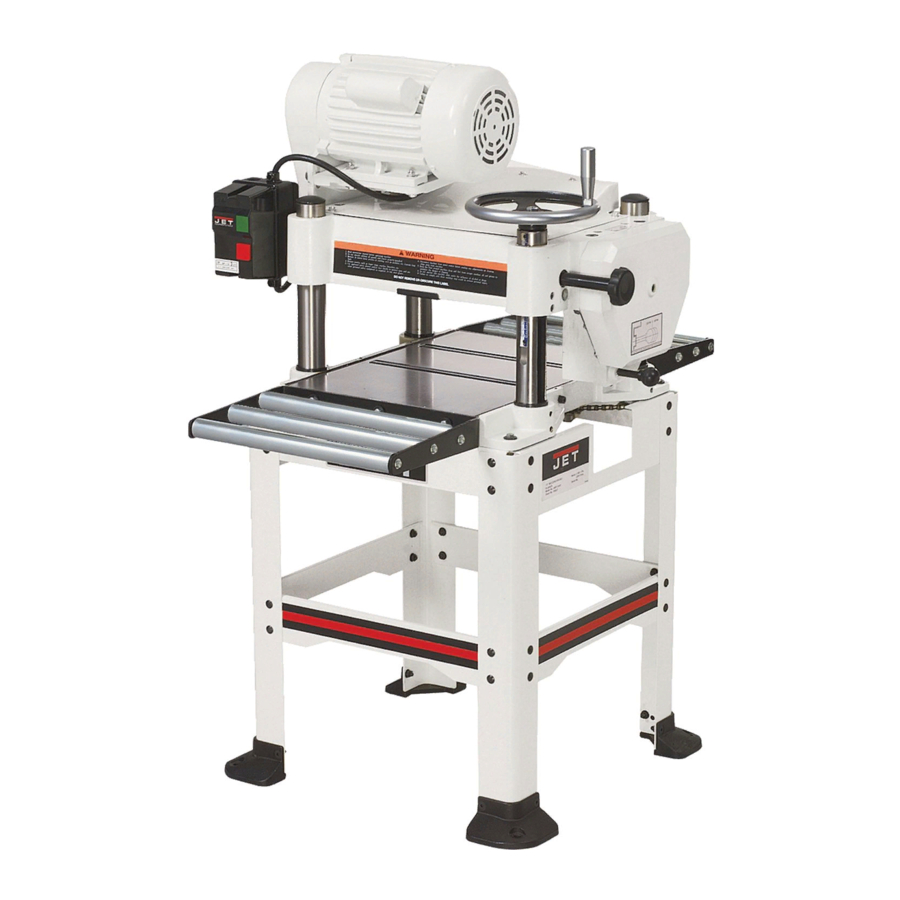
Page 7: Features Of The Jwp-16Os Planer
Maximum Full Width Depth of Cut (in.) ... 1/8 Maximum Opening (in.)... 6-3/8 x 16 Minimum Planing Length (in.) ... 8 Knives... 3 Planer Blade Size (L x W x T/in.) ... 16-1/8 x 1 x 1/8 Cutterhead Speed (RPM)... 4,500 Cuts per Minute... 13,500 Cutterhead Diameter (in.)...2-7/8 Feed Rate (FPM) ...16 &... -
Page 8: Receiving
Receiving Carefully unpack the planer and any loose items from the wood crate and inspect for damage. Any damage should be reported immediately to your distributor and shipping agent. Before proceeding further, read your manual thoroughly to familiarize yourself with proper assembly, maintenance and safety procedures. -
Page 9: Assembly
Assembly Most of the JWP-16OS Planer has been assembled at the factory. However some parts must be assembled after delivery. Use care when cleaning the cutterhead; the knives are very sharp. Stand Assembly Refer to Figure 1. 1. Cast Foot Assembly – Using parts from the... -
Page 10: Starter Box
Dust Collection Hood Referring to Figure 6: The dust collection hood (A) comes standard with the model JWP-16OS planer, and helps maintain a clean and safe work area. It is assembled to the planer (B) with six hex head screws (C) as shown. -
Page 11: Electrical Connections
Adjustments Overview Many parts are factory adjusted. The operator should be familiar with the following procedures to gain a better understanding of the JWP-16OS Planer's construction and operation. Control and Adjustments Refer to Figure 8 for general control and adjustment locations for the JWP-16OS Planer and are also listed below. -
Page 12: Pulleys And Belts
Pulleys and Belts The belt and pulley assembly are on the left side of the planer. To inspect for pulley alignment and correct belt tension, remove the four hex head screws (10mm) holding the cover in place. Figure 9 shows the assembly with the cover removed. -
Page 13: Table Rollers
Figure 13 Table Rollers Two table rollers (A, Fig. 14) ease stock movement as it is fed through the planer. The height of the rollers is dependent on the type of wood being planed. When planing rough stock, set the rollers slightly high to keep the lumber from dragging along the table. -
Page 14: Depth Of Cut Adjustment
(C,). After obtaining the proper height for the head assembly, tighten the lock knobs. Note: The JWP-16OS Planer has two lock knobs; one is located by the handwheel (C, Fig. 19). The other is located on the opposite (left rear) corner. -
Page 15: Removing And Replacing Knives
Planer knives are dangerously sharp. Use extreme caution when inspecting, removing, sharpening, or replacing knives into the cutterhead. Failure to comply may cause serious injury. 3. To check and adjust the knives, use the provided knife gauge (Fig. 22) and check all three knives. -
Page 16: Table Adjustment
the dust port. Remove the cover/dust port (Fig. 20) as a unit. The cutterhead assembly can be seen from the opening on top. Refer to Figure 21: 3. Loosen the gib (C) by turning the six gib screws (D) into the gib. Remove gib (C), knife (A) and springs (E). -
Page 17: Adjusting Work Table Parallel To Cutterhead (Fine Adjustment)
Cutterhead (Fine Adjustment) section. It the gap difference from one side to the other is grater than 0.016", the cutterhead assembly raising chain under the planer base needs to be adjusted – see the Adjusting Work Table Parallel to Cutterhead (Major Adjustment) section. -
Page 18: Transmitting Rollers
Experimentation will determine the best settings. Figure 29 Figure 30 Anti-Kickback The JWP-16OS Planer provides an anti- kickback safety feature. The anti-kickback fingers hang from a rod suspended across the front of the cutterhead casting (A, Fig. 28) and help prevent kickback of stock. It is necessary to inspect them regularly to make sure they hang freely. -
Page 19: Checking And Adjusting The Feed Roller Height
Checking and Adjusting the Feed Roller Height The infeed and outfeed rollers propel the lumber through the planer. The rollers also press the lumber flat against the planer table. The infeed and outfeed rollers are adjusted at the factory and are set at 0.020" below the knife- edge at bottom dead center (Fig. -
Page 20: Table Locks
Figure 33 Gearbox Referring to Figure 34: The JWP-16OS Planer is equipped with a spiral, serrated infeed roller (F) and a solid outfeed roller. When the feed rollers are engaged, they turn to feed the stock. The feed rollers are driven by chains (A) and sprockets (B) in the gearbox. -
Page 21: Power Feed
While cutting this much material is possible, it is not recommended. Depth Limiter The Model JWP-16OS Planer is equipped with a depth limiter – located on the bottom of the cutterhead casting just below the warning label (A, Fig. 37). The depth limiter controls maximum depth of cut to 1/8". -
Page 22: Maintenance
Maintenance General Inspect your planer each time before using. Check for the following conditions and repair or replace when necessary. 1. Loose mounting bolts. 2. Worn switch. 3. Worn or damaged cords and plugs. 4. Damaged V-belts. 5. Any other condition that could hamper the safe operation of this machine. -
Page 23: Lubrication
Lubrication The bearings on the cutterhead are factory lubricated and sealed for life – no lubrication required. Gearbox – The oil in the gearbox must be drained and replaced after the first 20 hours of operation. (See the Lubrication Table). Inspect levels periodically and change yearly. -
Page 24: Optional Accessories
Figure 41 Figure 42 Optional Accessories 708814 ... Knives (set of 3) 708119 ... Universal Mobil Base Figure 43... -
Page 25: Troubleshooting
Increase speed. Increase depth. Adjust feed roller tension. If proper tension cannot be achieve, replace feed rollers Clean pitch and residue, and wax planer table. Tighten transmission v-belt. Clear pitch and residue out of teeth. Adjust knife projection. Level bed. -
Page 26: Mechanical Troubleshooting
Check amp setting on motor starter. Verify that planer is on a circuit of correct size. If circuit size is correct, there is probably a loose electrical lead. -
Page 27: Parts List For The Jwp-16Os Planer
Parts List for the JWP-16OS Planer Head Assembly... -
Page 28: Head Assembly Parts List
Head Assembly Parts List Index No. Part No. Description Size Quantity 1 ...JWP16OS-101 ...Pulley Guard ... 1 2..JWP16OS-102 ...V-belt... M27 ... 3 3 ...TS-1491041 ...Hex Cap Screw ... M10×30L... 3 4 ...TS-1550071 ...Flat Washer... M10 ... 4 5 ...JWP16OS-105 ...Pulley Cover... 1 6 ...JWP16OS-106 ...Motor Cable... - Page 29 Head Assembly Parts List Index No. Part No. Description Size Quantity 57 ...JWP15H-007...Screw ... 18 58 ...TS-1503041 ...Socket Head Cap Screw... M6×16L... 8 59 ...TS-1524031 ...Socket Set Screw... M8×12L... 1 60 ...JWP15H-020...Spring... 4 61 ...JWP208-019 ...Bushing ... 4 62 ...JWP15H-022...Plate ... 4 63 ...TS-1490031 ...Hex Cap Screw ...
-
Page 30: Base Assembly
Base Assembly Base Assembly Parts List Index No. Part No. Description Size Quantity 1 ...JWP16OS-201 ...Lifting Handle ... 4 2 ...JWP15H-207...Nut Fixture... 4 3 ...JWP16OS-203 ...Leadscrew... 3 4 ...JWP16OS-204 ...Column... 4 5 ...TS-1523041 ...Socket Set Screw... M6×12L... 4 6 ...JWP15H-203...Column... 4 7 ...JWP16OS-207 ...Base ... - Page 31 Base Assembly Parts List Index No. Part No. Description Size Quantity 18 ...TS-1490041 ...Hex Cap Screw ... M8×25L... 2 19 ...BB-6202ZZ...Ball Bearing... 6202ZZ... 4 20 ...JWP15H-214...Retaining Ring ... RTW-35... 4 21 ...JWP15H-216...Sprocket ... 4 22 ...TS-0680041 ...Flat Washer... 3/8 ... 4 23 ...TS-1540072 ...Nut...
-
Page 32: Gear Box Assembly
Gear Box Assembly... -
Page 33: Gear Box Assembly Parts List
Gear Box Assembly Parts List Index No. Part No. Description Size Quantity 1 ...TS-1550041 ...Flat Washer... M6 ... 2 2 ...TS-1503031 ...Socket Head Cap Screw... M6×12L... 1 3..BB-6204ZZ...Ball Bearing... 6204ZZ... 1 4 ...JWP15H-304...Gear ... 1 5 ...TS-1503061 ...Cap Screw... M6x25L ... 6 6 ...BB-6201 ...Ball Bearing... -
Page 34: Stand Assembly Parts List
Stand Assembly Stand Assembly Parts List Index No. Part No. Description Size Quantity 1 ...JWP16OS-401 ...Upper Side Brace (L) ... 1 2 ...JWP16OS-402 ...Upper Front Brace ... 2 3 ...JWP16OS-403 ...Down Side Brace (R) ... 2 4 ...JWP16OS-404 ...Down Front Brace ... 2 5 ...TS-1550061 ...Flat Washer... - Page 35 Electrical Schematic for JWP-16OS Planer...
- Page 36 WMH TOOL GROUP 2420 Vantage Drive Elgin, IL 60123 Ph: 888-8097-7129 ▪ Fax: 800-274-6840 www.wmhtoolgroup.com...
Need help?
Do you have a question about the JWP-16OS and is the answer not in the manual?
Questions and answers