
Related Manuals for Jet JWP-12DX


Summary of Contents for Jet JWP-12DX
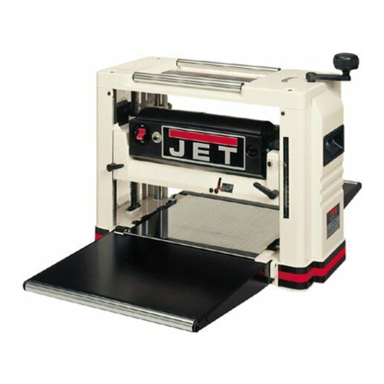
- Page 1 OWNER'S MANUAL JWP-12DX 12-1/2” Deluxe Wood Planer JET EQUIPMENT & TOOLS, INC. P.O. BOX 1349 Phone:253-351-6000 A WMH Company Auburn, WA 98071-1349 Fax: 1-800-274-6840 www.jettools.com e-mail jet@jettools.com M-708521 03/01...
-
Page 2: Warranty
Important Information 2-YEAR JET offers a two-year limited warranty on this product LIMITED WARRANTY REPLACEMENT PARTS Replacement parts for this tool are available directly form JET Equipment & Tools. To place an order, call 1-800-274-6848. Please have the following information ready: 1. -
Page 3: Warnings
WARNING For your own safety, read this instruction manual before operating the planer. Always wear eye protection. Do not wear gloves, necktie, or loose clothing. Do not force work through the machine. Allow the planer to apply the proper feed rate. Check the feed rollers before use for chips and sawdust lodged between any of the components. - Page 4 ALWAYS USE SAFETY GLASSES. Also use face or dust masks if the cutting operation is dusty. Everyday eyeglasses only have impact resistant lenses, they are NOT safety glasses. SECURE WORK. Use clamps or a vise to hold the work when it’s practical. It’s safer than using your hand and it frees both hands to operate the tool.
-
Page 5: Grounding Instructions
Grounding Instructions Caution: This tool must be grounded while in use to prevent electric shock. In the event of a malfunction or breakdown, grounding provides a path of least resistance for electric current to reduce the risk of electric shock. This tool is equipped with an electric cord having an equipment-grounding conductor and a grounding plug. -
Page 6: Table Of Contents
Shipping Weight (approx.) ......................64-1/2 lbs. Introduction The JET JWP-12DX planer you have purchased is a high quality tool that will give you years of superior service. You will get maximum performance and enjoyment from your new planer if you will take a few moments now to review the entire manual before beginning assembly and operation. -
Page 7: Contents Of The Shipping Container
WARNING Read and understand the entire contents of this manual before attempting assembly or operation! Failure to comply may cause serious injury! Contents of the Shipping Container Planer Chip Deflector Accessory Package: Handle Assembly Knife Setting Gauge 8mm x 50 Hex Socket Cap Screws 6mm x 16 Hex Socket Cap Screw 6mm Lock Washer Owner’s Manual... -
Page 8: Attaching The Planer To A Workbench Or Stand
Leveling the Extension Tables 1. The extensions were leveled with the table at the factory. If adjustment is necessary follow these steps: 2. Raise the cutterhead assembly by turning the handwheel. 3. Place a straight edge (A, Fig. 3) across both extension table rollers. - Page 9 board is narrow enough, consider using a Safety Switch tablesaw or bandsaw to rip the top of the warp before planing the board. If this is not practical, WARNING plane the top of the board until it is flush with Always make sure the switch is in the off the two sides of the board.
- Page 10 Grain Direction Planing Rough Lumber Always feed the board so the knives are cutting CAUTION in the same direction as the wood grain, as Make sure wood is properly dried before shown in Figure 9. If you cut against the grain, planing.
-
Page 11: Adjustments
The cutterhead has been adjusted parallel to the table at the factory. Use the following The JWP-12DX planer is designed for planing solid wood. Other material, including glue, will procedure to check and align the cutterhead parallel to the cutterhead: dull or damage the knives. -
Page 12: Removing And Installing Planer Knives
The table and the cutterhead should be adjusted 2. Lower the cutterhead as low as it will go. parallel at the factory. Only proceed with this adjustment if absolutely necessary. 3. Remove two hex socket cap screws (B, Fig. 13) and two lock washers holding the chip 1. -
Page 13: Maintenance
7. Rotate the cutterhead and install the second knife. 8. Install the chip guard. Carbon Brush Maintenance The JWP-12DX has two brushes that require periodic inspection and occasional replacement. If the motor is running properly, the brushes are good. If the motor slows down under a... - Page 14 contaminates and increase the wear on the Feed Roller Maintenance chain. The feed rollers are made of a rubber material To access the following lubrication points, and should be inspected after every hour of carefully turn the planer over on its side. operation: Beveled Gears - Apply a small dab of #2 1.
-
Page 15: Maintenance
Maintenance WARNING All repairs, adjustments, and maintenance must be performed with the planer unplugged from the power source! Failure to comply may cause serious injury! Brush off and blow out all the sawdust and chips inside the planer. Every one hour of running time Inspect the feed rollers (on either side of the cutterhead for any impacted wood chips. - Page 16 Too heavy a cut Remove less material Knives cutting against grain Torn Grain Cut with the grain Dull knives Sharpen knives Dull knives Sharpen knives Too heavy a cut Rough/Raised Grain Remove less material while planning Moisture content too high Remove moisture by drying or use dry wood Motor belt slipping Replace motor belt...
- Page 17 Head Assembly...
- Page 18 Parts List for the JWP-12DX Planer Head Assembly Index Part Description Size Qty. 1..PGM-C08........Handle Assembly ..............1 2..TS-1503041 ......Hex Socket Cap Screw ......M6×16 ......1 3..TS-1551041 ......Lock Washer......... M6 ......1 4..PGM-C11........Chain Guard................1 5..TS-1504031 ......Hex Socket Cap Screw ......M8×16 ......4 6..PGO-C01W ......Upper Guard .........
- Page 19 Index Part Description Size Qty. 54 ..PG060010.........Handle ..................2 55 ..PG010036.........Spring ..................1 ....PG010048K ......Knife Gauge Assembly (not shown).......... 1 ....JWP12-AP ........Accessory Package..............1...
- Page 20 Motor Assembly...
- Page 21 Motor Assembly Index Part Description Size Qty. 1..JWP12-101 .......Motor Casing................1 ....PGO-M ........Motor Assembly ............... 1 2..JWP12-102 .......Stator Assembly............... 1 3..JWP12-103 .......Plate ..................1 4..JWP12-104 .......Self-Tapping Screw..............2 5..PGA-M28 ........Motor Label ................1 6..BB-6201........Ball Bearing ................1 7..JWP12-107 .......Rotor Assembly........
- Page 22 Table Assembly...
- Page 23 Table Assembly Index Part Description Size Qty. 1..PGM-B01 ........Leadscrew (left)................ 1 2..JWP12-123 .......Double Round End Key ......4×4×8......2 3..PGM-B02 ........Bevel Gear................2 4..5FC-A03 ........E-Clip..................2 5..JWP12-123 .......Double Round End Key ......4×4×8......2 6..TS-1502021 ......Hex Socket Cap Screw ......M5×10 ......4 7..MGA-C31........Bracket ..........
Need help?
Do you have a question about the JWP-12DX and is the answer not in the manual?
Questions and answers