Table of Contents

Related Manuals for Jet JWP-208


Summary of Contents for Jet JWP-208
- Page 1 This manual is bookmarked Operating Instructions and Parts Manual Planer Model: JWP-208 WMH TOOL GROUP 2420 Vantage Drive Elgin, Illinois 60123 Part No. M-708528 Ph.: 800-274-6848 Revision G1 06/06 www.wmhtoolgroup.com Copyright © WMH Tool Group...
-
Page 2: Warranty And Service
Warranty and Service WMH Tool Group, Inc., warrants every product it sells. If one of our tools needs service or repair, one of our Authorized Service Centers located throughout the United States can give you quick service. In most cases, any of these WMH Tool Group Authorized Service Centers can authorize warranty repair, assist you in obtaining parts, or perform routine maintenance and major repair on your JET®... -
Page 3: Table Of Contents
Table of Contents Table of Contents... 3 Warnings ... 4 Features ... 6 Specifications ... 6 Receiving... 7 Installation & Assembly ... 7 Starter Box... 7 Handwheel... 8 Table Extension Rollers... 8 Dust Collection Hood... 8 Electrical Connections... 9 Extension Cords ... 9 Adjustments ... -
Page 4: Warnings
Read the manual. Always read the owner’s manual carefully before attempting to use the machine. Know the limitations and hazards associated with the use of this planer. Installation. If mounting machine to the floor, use high quality anchor bolts through the mounting holes on the base. -
Page 5: Safety Decals
Safety Decals Familiarize yourself with the location and content of these decals on your planer. 1. Read instruction manual before operating machine. 2. Do not operate without all guards properly installed. 3. Remove or fasten loose articles of clothing such as neckties, etc. -
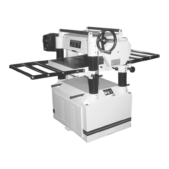
Page 6: Features
Features Fig. 2 Specifications Model No..JWP-208-1... JWP-208-3 Stock No... 708528... 708584 Table Area (D x W/in.)... 25-3/4 x 20... 25-3/4 x 20 Maximum Planing (W/in.) ... 20... 20 Maximum Planing (T/in.) ... 6... 6 Full Width Cutting Depth (in.) ... 3/32... 3/32 Minimum Planing Depth (in.)... -
Page 7: Receiving
Remove the screws that hold the planer to the shipping skid. Remove the protective coating from the table, bed rolls, feed rolls, cutterhead and loose items packed with the machine, including lifting handles and motor pulley. -
Page 8: Table Extension Rollers
Extension Rollers on page 11. Dust Collection Hood The dust collection hood (Fig. 6a) comes standard with the model JWP-208 planer, and helps maintain a clean and safe work area. It is assembled to the planer with the screws and washers as shown. -
Page 9: Electrical Connections
The machine must be properly grounded to help prevent electrical shock and possible fatal injury. A power plug is not provided with the 208 planer. You may either connect one or "hard-wire" the machine directly to your electrical panel provided there is a disconnect near the machine. -
Page 10: Table Rollers
Your planer is supplied with two table rollers (A, Fig. 12) which turn as the stock is fed into the planer, thus reducing friction. It is not possible to give exact dimensions on the proper height setting of the table rollers because each type of wood behaves differently. -
Page 11: Adjusting Table Extension Rollers
The table rollers are factory set for average planing and are parallel to the table surface. If you desire to adjust the table rollers higher or lower, proceed as follows: 1. Disconnect machine from power source. 2. Lay a straight edge (B, Fig. 14) across both rollers. -
Page 12: Adjusting Depth Of Cut
Always tighten the lock nuts before operating the planer. Cutterhead Adjustment Overview Although your planer was carefully adjusted at the factory, it should be checked before being put into operation. Any inaccuracies due to rough handling in transit can easily be corrected by following these directions. -
Page 13: Replacing & Resetting Knives
lightly backing out the six locking screws (F, Fig. 19) against the slot. NOTE: At this time, only tighten the knife in the slot just enough to hold knife in position. 6. If additional knives must be reset, repeat step 5. 7. -
Page 14: Adjusting Work Table Parallel To Cutterhead
If the work table is not parallel to the cutterhead, perform the adjustment procedure as follows: 1. Disconnect the machine from power source. 2. Tilt planer on its side to expose underside of base, as shown in Fig. 22. 3. Remove bolt (A, Fig. 22) and loosen bolt (B, Fig. -
Page 15: Anti-Kickback Fingers
E – Outfeed Roller The infeed roller (B, Fig. 23) and outfeed roller (F, Fig. 23) are those parts of your planer that feed the stock while it is being planed. The infeed and outfeed rollers are under spring tension and this... -
Page 16: Height Of Infeed Roller, Chipbreaker, Pressure Bar & Outfeed Roller
Height of Infeed Roller, Chipbreaker, Pressure Bar & Outfeed Roller The infeed roller, chipbreaker, pressure bar and outfeed roller are adjusted at the factory. The infeed roller and the chipbreaker should be set at 0.004” (0.1mm) below the cutting circle; and the outfeed roller should be set at 0.02”... -
Page 17: Feed Speed Control
Fig. 29. Changing Accessories for Lowest Feed Speed The lowest feed speed for your planer (16.2 fpm & 20.7 fpm) can be obtained by replacing the lower (gear shaft) sprocket and the chain. See Fig. 29. To change the sprocket and the chain on your machine, proceed as follows: 1. -
Page 18: Maintenance
Maintenance Periodic or regular inspections are required to ensure that the machine is in proper adjustment, that all screws are tight, that belts are in good condition, that dust has not accumulated in the electrical enclosures, and that there are no worn or loose electrical connections. - Page 19 Figure 32 Figure 33 Figure 34 Figure 35...
-
Page 20: Troubleshooting
Sharpen or replace knives. Increase speed. Increase depth. Adjust feed roller tension. If proper tension cannot be achieved, replace feed rollers. Clean pitch and residue, and wax planer table. Tighten transmission v-belt. Lightly roughen the feed roller surface with sandpaper. -
Page 21: Mechanical And Electrical Problems
If amp setting is correct then there is probably a loose electrical lead. Check amp setting on motor starter. Verify that planer is on a circuit of correct size. If circuit size is correct, there is probably a loose electrical lead. Check amp setting on motor starter. -
Page 22: Optional Accessories
Problem Possible Cause Motor failure. Miswiring of the unit. On/off switch failure. Optional Accessories (for the JWP-208 Planer) Stock No Description 708808 Knives, Single Sided (set of 4) 708583 Low Speed Gear Kit Ordering Replacement Parts To order parts or reach our service department, call 1-800-274-6848 between 7:30am and 5:31pm (CST), Monday through Friday. - Page 23 Head Assembly – Parts List Index Part No. Description Size 12 ...BB-6206ZZ...Ball Bearing... 6206ZZ... 1 13 ...JWP208-013 ...Key ... 8 x 8 x 36 ... 1 14 ...6292630 ...Pulley ..1 15 ...6292631 ...Washer..2 16 ...TS-1523071 ...Set Screw... M6 x 25 ... 2 17 ...JWP208-017 ...Motor Pulley ...
- Page 24 Head Assembly – Parts List Index Part No. 68 ...6292684 ...Handle..1 69 ...JWP208-069 ...Scale ..1 70 ...JWP208-070 ...Machine Screw ... M5 x 10 ... 2 71 ...JWP208-071 ...Pointer..1 72 ...6292814 ...Special Washer... M6 ... 3 73 ...JWP208-073 ...Cover...
-
Page 25: Head Assembly - Exploded View
Head Assembly – Exploded View... -
Page 26: Table And Roller – Parts And Assembly
Table and Roller – Parts and Assembly Index Part No. Description Size 1 ...JWP208-201 ...Middle Table..1 2 ...6292722 ...Roller..2 3 ...BB-6201ZZ...Ball Bearing... 6201ZZ... 4 4 ...6292724 ...Eccentric Shaft..1 5 ...TS-1523041 ...Set Screw... M6x12 ... 4 6 ...6292725 ...Lock Bar ... -
Page 27: Stand And Motor - Parts And Assembly
Stand and Motor – Parts and Assembly Index Part No. Description Size 1 ...JWP208-401 ...Stand..1 2 ...JWP208-402 ...Cover..2 3 ...TS-2286201 ...Flat Head Machine Screw... M6 x 20 ... 8 4 ...6292796 ...Bar..2 5 ...JWP208-405 ...Motor Mount ..1 6 ...TS-1524011 ...Set Screw... -
Page 28: Base And Column - Parts List
Base and Column – Parts List Index Part No. Description Size 1 ...JWP208-301 ...Base ..1 2 ...TS-1525021 ...Set Screw... M10 x 12 ... 8 3 ...JWP208-303 ...Column..3 4 ...JWP208-304 ...Column..1 5 ...JWP208-305 ...Lead Screw ..3 6 ...JWP208-306 ...Lead Screw ... -
Page 29: Base And Column - Assembly
Base and Column – Assembly... -
Page 30: Gearbox - Parts List
Gearbox – Parts List Index Part No. Description 1 ...JWP208-501 ...Gear Box ..1 2 ...OS-28408...Oil Seal..1 3 ...BB-6204ZZ...Ball Bearing... 6204ZZ... 1 4 ...6292762 ...Gear ... 16T... 1 5 ...TS-1503061 ...Socket Head Cap Screw... M6 x 25 ... 1 6 ...TS-1550041 ...Washer... -
Page 31: Gearbox - Assembly
Gearbox – Assembly... -
Page 32: Wiring Diagrams
Wiring Diagrams 230V 3HP Single Phase... -
Page 33: 230V 5Hp Three Phase
230V 5HP Three Phase... -
Page 34: 460V 5Hp Three Phase
460V 5HP Three Phase... - Page 35 Notes...
- Page 36 WMH TOOL GROUP 2420 Vantage Drive Elgin, IL 60123 800-274-6848 www.wmhtoolgroup.com...
Need help?
Do you have a question about the JWP-208 and is the answer not in the manual?
Questions and answers