Table of Contents
Advertisement
This .pdf document is bookmarked
This manual is bookmarked
Operating Instructions and Parts Manual
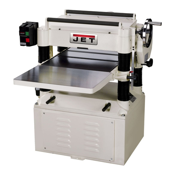
20-inch Planer
Models JWP-208 and JWP-208HH
Model JWP-208HH shown
JET
427 New Sanford Road
LaVergne, Tennessee 37086
Part No. M-708528
Ph.: 800-274-6848
Revision K 11/2018
www.jettools.com
Copyright © 2014 JET
Advertisement
Table of Contents

Related Manuals for Jet JWP-208HH


Summary of Contents for Jet JWP-208HH
- Page 1 This .pdf document is bookmarked This manual is bookmarked Operating Instructions and Parts Manual 20-inch Planer Models JWP-208 and JWP-208HH Model JWP-208HH shown 427 New Sanford Road LaVergne, Tennessee 37086 Part No. M-708528 Ph.: 800-274-6848 Revision K 11/2018 www.jettools.com Copyright © 2014 JET...
-
Page 2: Warranty And Service
JET sells through distributors only. The specifications listed in JET printed materials and on official JET website are given as general information and are not binding. JET reserves the right to effect at any time, without prior notice, those alterations to parts, fittings, and accessory equipment which they may deem necessary for any reason ®... -
Page 3: Table Of Contents
Knife Adjustment (Model JWP-208 only) ..................... 12 Replacing & Resetting Knives (Model JWP-208 only) ................13 Replacing or Rotating Knife Inserts (Model JWP-208HH only) ............... 14 Checking Work Table Parallel to Cutterhead ..................14 Adjusting Work Table Parallel to Cutterhead ..................15 ... -
Page 4: Warnings
Warnings Read the manual. Always read the owner’s manual carefully before attempting to use the machine. Know the limitations and hazards associated with the use of this planer. Installation. If mounting machine to the floor, use high quality anchor bolts through the mounting holes on the base. -
Page 5: Stand Mounting Holes
WARNING: Drilling, sawing, sanding or machining wood products generates wood dust and other substances known to the State of California to cause cancer. Avoid inhaling dust generated from wood products or use a dust mask or other safeguards for personal protection. Wood products emit chemicals known to the State of California to cause birth defects or other reproductive harm. -
Page 6: Features
Net Weight (approx. lbs.) ............640 ............753 *pre-wired 230V The specifications in this manual are given as general information and are not binding. JET reserves the right to effect, at any time and without prior notice, alterations to parts, fittings, and accessory equipment... -
Page 7: Receiving
Receiving Carefully unpack the planer and any loose items from the wood crate and inspect for damage. Any damage should be reported immediately to your distributor and shipping agent. Before proceeding further, read your manual thoroughly to familiarize yourself with proper assembly, maintenance and safety procedures. -
Page 8: Handwheel
5. Mount the second extension table to the opposite side of the planer table, using the same procedure. Figure 6a - JWP-208HH only Dust Collection Hood The dust collection hood (Fig. 6b) comes standard with the model JWP-208 planer, and helps maintain a clean and safe work area. -
Page 9: Electrical Connections
Electrical Connections Electrical connections must be made by a qualified electrician in compliance with all relevant codes. The machine must be properly grounded to help prevent electrical shock and possible fatal injury. A power plug is not provided with the 208 planer. You may either connect one or "hard-wire"... -
Page 10: Overview
2. Check belt tension. Proper tension is obtained when there is approximately 1/4” deflection of the center span of the pulleys using light finger pressure (Fig. 10). Figure 10 3. If adjustment of belt tension is necessary, loosen one pair of hex nuts (E & F, Fig. 11) and turn the other pair to raise or lower the motor plate. -
Page 11: Adjusting Table Extension Rollers
Note: When raising the roller higher above the table, the available range is from .003” to .006” See Fig. 13. Figure 13 The table rollers are factory set for average planing and are parallel to the table surface. If you desire to adjust the table rollers higher or lower, proceed as follows: 1. -
Page 12: Adjusting Depth Of Cut
Adjusting Depth of Cut The cutting depth scale (A, Fig. 16) is a combination inch/metric scale with a cutting range from 0 to 8” (204mm). The distance of upward or downward movement controlled handwheel (B, Fig. 16). One revolution of the handwheel is .059”... -
Page 13: Replacing & Resetting Knives (Model Jwp-208 Only)
NOTE: At this time, only tighten the knife in the slot just enough to hold knife in position. 6. If additional knives must be reset, repeat step 5. 7. After all four knives are set with screws just snug, back out and tighten the six locking screws (F, Fig. -
Page 14: Replacing Or Rotating Knife Inserts (Model Jwp-208Hh Only)
Replacing or Rotating Knife Inserts (Model JWP-208HH only) The knife inserts on the model JWP-208HH are four-sided. When dull, simply remove each insert, rotate it 90° for a fresh edge, and re-install it. Use the provided star point screwdriver to remove the knife insert screw. -
Page 15: Adjusting Work Table Parallel To Cutterhead
1. Disconnect machine from power source. 2. Place the gauge block (Figure 21) on the work table directly under the edge of a knife or knife insert as shown. Make slight contact with the knife edge by gently raising the table. 3. -
Page 16: Anti-Kickback Fingers
Anti-Kickback Fingers The anti-kickback fingers (A, Fig 23) help prevent kickback of stock. They operate by gravity and it is necessary to inspect them occasionally to make sure they are free of gum and pitch, so that they move independently and operate correctly. Adjusting Infeed &... -
Page 17: Feed Speed Control
4. Move the gauge block (J, Fig. 27) under one end 4. When the sprockets (B, Fig. 28) are of the outfeed roller (F, Fig. 27). The bottom of removed, replace the lower sprocket the outfeed roller should just touch the top of the which will be assembled on the gear gauge block. -
Page 18: Maintenance
Lubrication Maintenance The bearings on the cutterhead are factory Periodic or regular inspections are required to lubricated and sealed for life – no lubrication ensure that the machine is in proper adjustment, required. that all screws are tight, that belts are in good condition, that dust has not accumulated in the The lubricant in the gearbox must be replaced electrical enclosures, and that there are no worn... - Page 19 [The item numbers on this chart are referenced with the accompanying illustrations.] Position Interval Suitable Types of Lubricant Fig. No. Drive Chain Frequently Grease Gear Box When operated more than 70 to 90 weight gear oil 2,500 hours Return Rollers Frequently SAE-30 Worm Gear...
-
Page 20: Troubleshooting
Troubleshooting Operating Problems Problem Possible Cause Solution Snipe. Table rollers not set properly. Adjust rollers to proper height. Inadequate support of long Support long boards with extension rollers. boards. (Snipe cannot be eliminated, but can Uneven feed roller pressure Adjust feed roller tension. be minimized so front to back. - Page 21 Problem Possible Cause Solution Chain jumping. Inadequate tension. Adjust chain tension. Sprockets misaligned. Align sprockets. Sprockets worn. Replace sprockets. Machine will not No incoming power. Verify unit is connected to power. start/restart or Overload automatic reset has When planer overloads on the circuit breaker repeatedly trips not reset.
-
Page 22: Optional Accessories
708583 ... Low Speed Gear Kit 708808 ... Knives, Single Sided (set of 4) – model JWP-208 only 1791212 ..Knife Inserts (set of 10) – model JWP-208HH only Ordering Replacement Parts To order parts or reach our service department, call 1-800-274-6848, Monday through Friday (see our website for business hours, www.jettools.com). - Page 23 Head Assembly – Parts List Index Part No. Description Size 25 ..... TS-1540041 ..... Hex Nut ..............M6 ....... 8 26 ..... JWP208-026A ..Key ............... 5 x 5 x 24 ....2 27 ..... 6292643 ....Sprocket ....................1 28 .....
- Page 24 111 ... JWP208HH-111 ..Knife Insert Screw** ..........#10-32 x 1/2” ..... 92 112 ... JJ6HH-113 ....Star Point Screwdriver (not shown)** ............2 ** Index # 109 thru 112 are used only on the helical cutterhead, model JWP-208HH...
-
Page 25: Head Assembly - Exploded View
Head Assembly – Exploded View... - Page 26 20 ..... TS-1524051 ..... Socket Set Screw** ..........M8x20 ......6 21 ..... TS-1490041 ..... Hex Cap Screw** ..........M8x25 ......6 * Index #11 thru 18 are used only on the model JWP-208. ** Index #19, 20 and 21 are used only on the model JWP-208HH.
-
Page 27: Stand And Motor - Parts And Assembly
18 ..... JWP208-418 .... Strain Relief....................1 ....JWP208HH-418 ..Strain Relief (for 5HP, 1PH, 230V only) ........... 1 19 ..... TS-0680031 ..... Washer ..............5/16 ......4 20 ..... STRIPE-1-3/4 ... JET Stripe (not shown) ........1-3/4 w ....per ft. -
Page 28: Base And Column - Parts List
Base and Column – Parts List Index Part No. Description Size 1 ....JWP208-301 .... Base ......................1 2 ....TS-1525021 ..... Set Screw ............. M10 x 12 ..... 8 3 ....JWP208-303 .... Column ..................... 3 4 ....JWP208-304 .... Column ..................... 1 5 .... -
Page 29: Base And Column - Assembly
Base and Column – Assembly... -
Page 30: Gearbox - Parts List
Gearbox – Parts List Index Part No. Description Size 1 ....JWP208-501 .... Gear Box ....................1 2 ....OS-28408 ....Oil Seal ..................... 1 3 ....BB-6204ZZ ....Ball Bearing ............6204ZZ......1 4 ....6292762 ....Gear ..............16T ......1 5 .... -
Page 31: Gearbox - Assembly
Gearbox – Assembly... -
Page 32: Wiring Diagrams
Wiring Diagrams 230V 3HP Single Phase 13NO 14NO ManAuto... -
Page 33: 230V 5Hp Single Phase
230V 5HP Single Phase 13NO 14NO ManAuto... -
Page 34: 230V 5Hp Three Phase
230V 5HP Three Phase 13NO 14NO ManAuto... -
Page 35: 460V 5Hp Three Phase
460V 5HP Three Phase 13NO 14NO ManAuto... - Page 36 427 New Sanford Road LaVergne, Tennessee 37086 Phone: 800-274-6848 www.jettools.com...
Need help?
Do you have a question about the JWP-208HH and is the answer not in the manual?
Questions and answers