Table of Contents
Advertisement
This .pdf document is bookmarked
Operating Instructions and Parts Manual
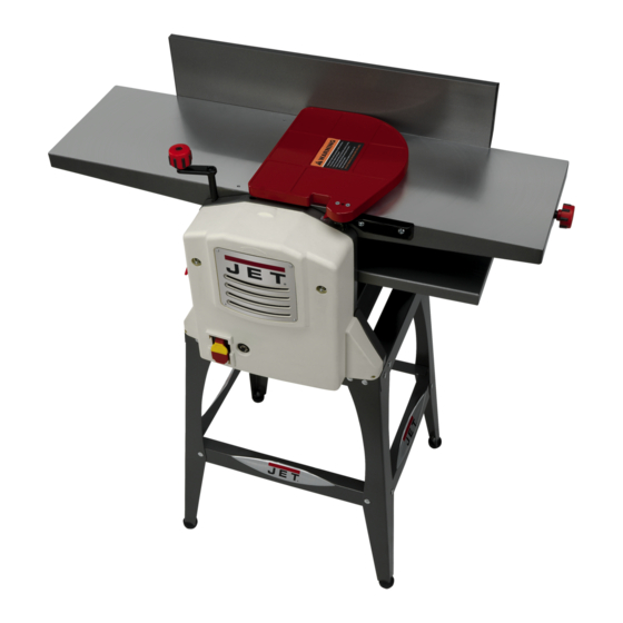
JJP-10BTOS 10" Jointer-Planer
WALTER MEIER (Manufacturing) Inc.
427 New Sanford Road
LaVergne, Tennessee 37086
Part No. M-707410
Ph.: 800-274-6848
Revision A1 12/09
www.waltermeier.com
Copyright © 2009 Walter Meier (Manufacturing) Inc.
Advertisement
Table of Contents

Related Manuals for Jet JJP-10BTOS


Summary of Contents for Jet JJP-10BTOS
- Page 1 This .pdf document is bookmarked Operating Instructions and Parts Manual JJP-10BTOS 10" Jointer-Planer WALTER MEIER (Manufacturing) Inc. 427 New Sanford Road LaVergne, Tennessee 37086 Part No. M-707410 Ph.: 800-274-6848 Revision A1 12/09 www.waltermeier.com Copyright © 2009 Walter Meier (Manufacturing) Inc.
-
Page 2: Warranty And Service
Walter Meier is consistently adding new products to the line. For complete, up-to-date product information, check with your local Walter Meier distributor, or visit waltermeier.com. WARRANTY JET products carry a limited warranty which varies in duration based upon the product (MW stands for Metalworking, WW stands for Woodworking). WHAT IS COVERED? This warranty covers any defects in workmanship or materials subject to the exceptions stated below. -
Page 3: Table Of Contents
Table of Contents Warranty and Service..........................2 Table of Contents .............................3 Warnings..............................4 Features ..............................7 Specifications ............................7 Optional Accessories ..........................7 Shipping Contents ............................8 Assembly ............................... 10 Jointer Setup ............................12 Planer Setup ............................12 Operating Controls..........................13 Adjustments ............................15 Basic Operations ............................ 18 Maintenance ............................ -
Page 4: Warnings
Warnings 1. Read and understand the entire owner's manual before attempting assembly or operation. 2. Read and understand the warnings posted on the machine and in this manual. Failure to comply with all of these warnings may cause serious injury. 3. - Page 5 20. Keep visitors a safe distance from the work area. Keep children away. 21. Make your workshop child proof with padlocks, master switches or by removing starter keys. 22. Give your work undivided attention. Looking around, carrying on a conversation and “horse-play” are careless acts that can result in serious injury.
- Page 6 36. When working with a swirl grain wood or burls, making it necessary to plane against the grain, use a lesser depth of cut and a slow rate of feed. 37. Move the hands in an alternate motion from back to front as the work continues through the cut. Never pass the hands directly over the cutter knife.
-
Page 7: Features
Features Features Specifications Model number ........................JJP-10BTOS Stock number ........................... 707410 Cutterhead speed ........................9000rpm Number of knives..........................2 Cutter knife length........................10-1/4" Cutter knife thickness ........................0.060" Dust port diameter ....................... 2-1/2" or 4” Jointer table ........................36"x10-1/4” Max stock removal .......................... 1/8”... -
Page 8: Shipping Contents
Shipping Contents Figure 1 – Contents of the Main Carton Unpacking Contents of the Main Carton Remove all contents from the shipping carton. 01 Jointer Fence (A)0 Do not discard the carton or packing material until your Model JJP-10BT Jointer-Planer is 01 Dust Chute (B) assembled and is running satisfactorily. - Page 9 Knobs and Handles 01 Lock Knob (R) 01 Height Adjust Handle (S) 01 Lock Handle (U) 01 Flat Washer (T) 01 Lock Knob (V) Figure 3 – Knobs and Handles Hardware 04 Hex Cap Screw(X) 24 Carriage Bolt (Y) 02 Socket Head Cap Screw (Z) 03 Socket Head Cap Screw (AA) 04 Socket Head Cap Screw (BB) 28 Flat Washer (CC)
-
Page 10: Assembly
Assembly assembly convenience, item letter designators used throughout the Assembly section DD CC are the same as those used to identify shipping content and hardware components on pages 8–9. Stand Assembly EE DD CC Referring to Figure 5: 1. Select two legs (N),one short stand top support (H) and one short support plate (E). - Page 11 Jointer-Planer Assembly Referring to Figure 7: Fence 1. Attach jointer fence (A) to back of jointer outfeed table (F ) with two each socket head cap screws (Z) and lock washers (MM). Tighten screws with 5mm hex wrench (provided). Lock Knobs The JJP-10BT Jointer-Planer comes equipped with two lock knobs to secure the position of the jointer infeed table.
-
Page 12: Jointer Setup
Jointer Setup Disconnect machine from power source before making any adjustments. Failure to comply may cause serious injury. Referring to Figure 9: 1. Loosen lock handle (U). 2. Install planer table height adjustment handle (S). 3. Turn handle (S) counterclockwise and lower planer table (F ) all the way. -
Page 13: Operating Controls
Operating Controls Disconnect machine from power source before making any adjustments. Failure to comply may cause serious injury. Power Plug power cord into outlet. Referring to Figure 11: Start/Stop Pull the red switch (A) out to start. Push in to stop. Safety Key Removing the safety key (B) will render the start/stop switch inoperable. - Page 14 Jointer Controls and Adjustments Refer to Figure 13. Infeed Table Height Adjustment Two lock knobs (F) and a height adjustment knob (E) control the height adjustment of the infeed table (D). To adjust: 1. Loosen lock knobs (F). 2. Turn the height adjustment knob (E) clockwise to raise the infeed table (D) or counter-clockwise to lower the table.
-
Page 15: Adjustments
Adjustments Cutterhead Knife Adjustment Cutterhead knives dangerously sharp! Use extreme caution when inspecting, removing, sharpening or replacing knives into the cutterhead. Failure to comply may cause serious injury! Determining if adjustment is necessary: 1. Disconnect machine from the power source. 2. -
Page 16: Replacing Cutter Knives
Replacing Cutter Knives Jointer Fence Adjustment Referring to Figure 16: Disconnect machine from power The jointer fence (A) can be adjusted from a full forward source before making any adjustments. Failure position (90º to table, corresponding to a scale reading to comply may cause serious injury. - Page 17 Belt Replacement Refer to Figure 17 when installing or replacing the the feed-roller (A) or cutterhead drive (D) belts. Disconnect machine from power source before making any adjustments. Failure to comply may cause serious injury. Feed-roller Belt Replacement Cutterhead knives dangerously sharp.
-
Page 18: Basic Operations
Hand placement Basic Operations Never pass hands directly Dust Collection over the cutterhead. Before initial operation, the machine must be Referring to Figure 18: connected to a dust collector. At the start of the cut, the left hand holds the Important: If a dust collection system is not workpiece firmly against the infeed table and used, the quality of your cut will suffer severely. - Page 19 Direction of Grain Edge Jointing Avoid feeding work into the jointer against the Jointing (or edging) is the process of creating a finished, flat edge surface that is suitable for grain (Figure 20). joinery or finishing (Figure 22). It is also a necessary step prior to ripping stock to width on a table saw.
-
Page 20: Planer Operations
Beveling lowering the planer table (D, Fig. 12) using the adjustable handle (C, Fig. 12). Beveling an edge is the same operation as edge jointing, except that the fence is tilted to a The quality of thickness planing depends on specified angle. - Page 21 These can be purchased Feed the work in the direction of the grain. from JET – Stock # 709207. See Optional Work fed against the grain will have Accessories on page 7. chipped, splintered edges.
-
Page 22: Maintenance
the stone's surface is flush with the knife Maintenance bevel. 6. Keep the cutterhead from rotating by Blade Care grasping the cutterhead pulley while sliding Blades are extremely sharp! the stone back and forth across the table. Use caution when cleaning 7. -
Page 23: Troubleshooting
Troubleshooting Performance Troubleshooting – Jointer Trouble Probable Cause Remedy Finished stock is Align cutterhead knives with outfeed table. See Cutterhead Knife concave on back Knife is higher than outfeed table. Adjustment on page 15. end. Finished stock is Align cutterhead knives with outfeed concave on front end. - Page 24 Performance Troubleshooting – Planer Trouble Probable Cause Remedy Snipe Inadequate support of long boards. Support long boards with extension rollers. Dull knives. Sharpen knives. Note: Snipe can be minimized but not Lumber not butted properly. Butt end to end each piece of stock eliminated as they pass through.
- Page 25 Mechanical Troubleshooting – Planer/Jointer Trouble Probable Cause Remedy Machine will No incoming 1. Verify unit is connected to power and Start/Stop switch is in the not start/ Start position (see Power on page 13). power. restart or 2. Verify unit is connected to power. Set the Start/Stop switch to repeatedly the Stop position, depress and release the reset switch, then trips circuit...
-
Page 26: Parts
Parts Ordering Replacement Parts To order parts or reach our service department, call 1-800-274-6848 between 7:30am and 5:30pm (CST), Monday through Friday. Having the Model Number and Serial Number of your machine available when you call Jointer/Planer – Parts List Note: Parts without part numbers are for reference only and cannot be purchased individually. - Page 27 Jointer/Planer – Parts List Index No. Part No. Description Size 50 .... JJP8BT-50 ....Outfeed Table Spacer ................. 4 51 .... JJP8BT-51 ....Infeed Table Spacer................4 52 .... JJP8BT-52 ....Bearing ....................1 53 .... JJP8BT-53 ....Spring ....................2 54 .... JJP8BT-54 ....Bushing Block ..................5 55 ....
- Page 28 129 ..JJP8BT-129 ....Belt ....................1 130 ..JJP8BT-130 ....Shaft ....................2 131 ..JJP8BT-131 ....Front Support Cover ................1 132 ..JJP8BT-132 ....JET Nameplate................... 1 133 ..JJP8BT-133 ....Key ....................1 134 ..JJP8BT-134 ....Washer ....................1 135 ..JJP8BT-135 ....Sprocket .................... 1 136 ..
- Page 29 Jointer/Planer – Parts List Index No. Part No. Description Size 164 ..JJP10BT-164...Infeed Table ..................1 165 ..TS-1521051 ....Set Screw ............M4x12......2 166 .........Cord Clamp ..................1 167 .........Motor Housing ..................1 168 ..JJP8BT-168 ....Brush Holder ..................2 169 ..
- Page 30 10" JOINTER-PLANER ASSEMBLY DRAWING INDEX...
- Page 31 Planer Table Assembly...
- Page 32 Motor Front Frame Assembly...
- Page 33 Chain Drive Assembly Front Cover Assembly...
- Page 34 Cutterhead Guard Assembly Dust Cover Assembly...
- Page 35 Jointer Infeed Table Assembly Jointer Outfeed Table Assembly (10")
- Page 36 Cutter Head/Feed Roller Assembly Jointer Fence Assembly...
- Page 37 Rear Frame and Cover Assembly...
- Page 38 Jointer/Planer Stand Index No. Part No. Description Size 1 ....JJP10BT-901...Stand Top Support, Short ..............2 2 ....JJP10BT-902...Leg ....................4 3 ....JJP10BT-903...Support Plate, Long ................2 4 ....JJP10BT-904...Support Plate, Short................2 5 ....JJP10BT-905...Stand Top Support, Long ..............2 6 ....
-
Page 39: Electrical Connection
Electrical Connection... - Page 40 WALTER MEIER (Manufacturing) Inc. 427 New Sanford Road LaVergne, Tennessee 37086 Phone: 800-274-6848 www.waltermeier.com...
Need help?
Do you have a question about the JJP-10BTOS and is the answer not in the manual?
Questions and answers