
Related Manuals for Jet JWP-208HH-BLK


Summary of Contents for Jet JWP-208HH-BLK
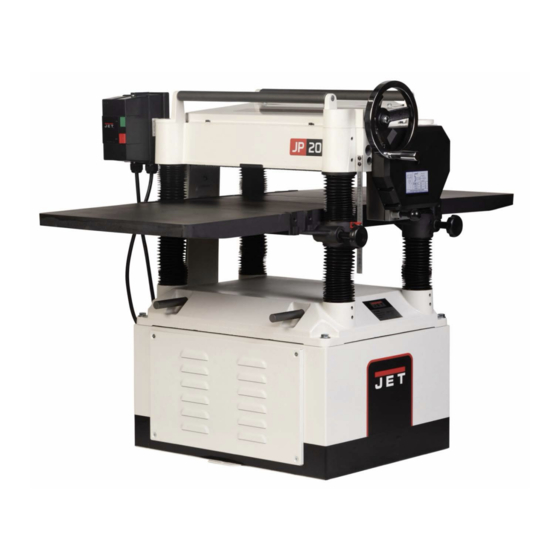
- Page 1 Operating Instructions and Parts Manual 20-inch Planer Models JWP-208HH-BLK 427 New Sanford Road LaVergne, Tennessee 37086 Part No. M-JT1-1374 Ph.: 800-274-6848 Edition 3 08/2024 www.jettools.com Copyright ©2024 JET...
-
Page 2: Warranty And Service
JET sells through distributors only. The specifications listed in JET printed materials and on official JET website are given as general information and are not binding. JET reserves the right to effect at any time, without prior notice, those alterations to parts, fittings, and accessory equipment which they may deem necessary for any reason whatsoever. -
Page 3: Table Of Contents
Table of Contents Warranty and Service ........................... 2 Table of Contents ............................3 Warnings ..............................4 Stand Mounting Holes ..........................5 Introduction ..............................6 Features ............................... 6 Specifications ............................... 7 Unpacking ..............................8 Installation & Assembly ..........................9 Starter Box ..............................9 Handwheel .............................. -
Page 4: Warnings
JET Black coating. This machine has an industrial-grade low-friction corrosion-resistant coating we call JET Black. This coating is on the main table and the infeed and outfeed tables. While the JET Black coating is durable, it can be damaged if metal or other hard and/or sharp objects strike, gouge, or scratch the surface. -
Page 5: Safety Decals
Safety Decals Familiarize yourself with the location and content of these decals on your planer. 6. Disconnect machine from power source before making any 1. Read instruction manual before operating machine. adjustments or cleaning chips away from machine. 2. Do not operate without all guards properly installed. 7. -
Page 6: Introduction
Introduction This manual is provided by JET covering the safe operation and maintenance procedures for a JET Model JWP-208HH-BLK planer. This manual contains instructions on installation, safety precautions, general operating procedures, maintenance instructions and parts breakdown. This machine has been designed and constructed to provide consistent, long-term operation if used in accordance with instructions set forth in this manual. -
Page 7: Specifications
Gross Weight (approx. lbs.) ........................765 The specifications in this manual are given as general information and are not binding. JET reserves the right to effect, at any time and without prior notice, alterations to parts, fittings, and accessory equipment... -
Page 8: Unpacking
Hex Wrenches (3,4,5 and 6mm) Star point screwdrivers 10 Knife inserts 10 Knife insert screws JET Black Coated Extension Tables Hardware Bag for Extension Tables : 6 Hex Cap Screws, M8 x 1.25P x 25 6 Socket Set Screws, M8 x 1.25P x 12 Owner’s Manual (not shown) -
Page 9: Installation & Assembly
Installation & Assembly This machine industrial-grade low-friction corrosion- resistant coating on the main table and the infeed and outfeed tables. While the coating is durable, it can be damaged if metal or other hard and/or sharp objects strike, gouge, or scratch the surface. -
Page 10: Extension Tables
Extension Tables 1. Mount the first JET Black coated extension table to the edge of the main table with three M8 x 25 hex cap screws (see Figure 6). Do not fully tighten yet. 2. The extension table must be leveled with the main table. -
Page 11: Electrical Connections
Electrical Connections Electrical connections must be made by a qualified electrician in compliance with all relevant codes. The machine must be properly grounded to help prevent electrical shock and possible fatal injury. A power plug is not provided with the JWP-208HH- BLK planer. -
Page 12: Adjusting Depth Of Cut
3. Check belt tension. Proper tension is obtained when there is approximately 1/4” deflection of the center span of the pulleys using light finger pressure (Figure 11). Figure 11 4. If adjustment of belt tension is necessary, loosen one pair of hex nuts (E & F, Figure 12) and turn the other pair to raise or lower the motor plate. -
Page 13: Replacing Or Rotating Knife Inserts
Replacing or Rotating Knife Inserts Disconnect machine from power source. The knife inserts are four-sided. When dull, simply remove each insert, rotate it 90° for a fresh edge, and re-install it. Use the provided star point screwdriver to remove the knife insert screw (see Figure 14). It is advisable to rotate all inserts at the same time to maintain consistent cutting. -
Page 14: Checking Work Table Parallel To Cutterhead
Checking Work Table Parallel to Cutterhead The work table is set parallel to the cutterhead at the factory and no further adjustment should be necessary. If your machine is planing a taper, first check to see if the knives are set properly in the cutterhead. -
Page 15: Anti-Kickback Fingers
Know the Transmitting Rollers of Your Planer A – Anti-Kickback Fingers B – Infeed Roller C – Chipbreaker D – Cutterhead E – Pressure Bar F – Outfeed Roller The infeed roller (B, Figure 18) and outfeed roller (F, Figure 18) are those parts of your planer that feed the stock while it is being planed. -
Page 16: Feed Speed Control
If an adjustment to the The Low Speed Gear Kit (708583) is an outfeed roller is necessary, loosen the lock optional accessory you can order from JET nut (L, Figure 22) and turn screw (M, Figure Tools service department. - Page 17 Figure 24 3. There are two safety plates attached to the rear of the gear box cover. These plates are on each side of the gear box cover and can’t be seen when the cover is installed. The safety plates are held in place by mounting screws which are accessed from the front of the gear box cover (see Figure 25) Remove the top mounting screws on each safety plate (see...
-
Page 18: Return Rollers
Return Rollers 8. Remove the lower gear shaft sprocket and replace with smaller sprocket from kit. The two return rollers on the top of the Reattach the washer and hex cap screw to machine serve as a convenient rest for stock. secure the new lower gear shaft sprocket. -
Page 19: Maintenance
Maintenance Disconnect machine from power source before doing maintenance. Failure to comply may cause serious injury. This machine industrial-grade low-friction corrosion- resistant coating on the main table and the infeed and outfeed tables. While the coating is durable, it can be damaged if metal or Figure 30 other hard and/or sharp objects strike, gouge, or scratch the surface. - Page 20 Figure 32 4. Using a 6mm hex wrench, remove gear box cover mounting screw located in the center of Figure 34 cover (see Figure 33). With this screw removed, adjust the cover to allow the right- 7. Replace and tighten oil drain plug in gear side safety plate to swing down freely.
- Page 21 [The item numbers on this chart are referenced with the accompanying illustrations.] Position Interval Suitable Types of Lubricant Fig. No. Drive Chain Frequently Grease Gear Box When operated more than 70 to 90 weight gear oil 34,35 2,500 hours Return Rollers Frequently SAE-30 Worm Gear...
-
Page 22: Troubleshooting
Troubleshooting Operating Problems Problem Possible Cause Solution Inadequate support of long Support long boards with extension rollers. Snipe. boards. Uneven feed roller pressure Adjust feed roller tension. (Snipe cannot be front to back. eliminated but can be minimized so Dull Knives. Rotate or replace knife inserts. - Page 23 OFF button and allow unit to adequately cool before attempting restart. If problem persists, contact JET technical support. One cause of overloading trips is too deep a Planer frequently trips. cut. If too deep a cut is not the problem, check the sharpness of the blade inserts.
-
Page 24: Optional Accessories
Problem Possible Cause Solution Miswiring of the unit. Double check to confirm all electrical connections are correct and tight. Refer to wiring diagram on page 34 to make any needed corrections. Optional Accessories Stock No Description 708119 .... Mobile Base 708520 .... -
Page 25: Stand And Motor - Parts And Exploded View
18 ....JWP208HH-418A ..Strain Relief ....................1 19 ....TS-0680031 ....Washer ..............5/16 ....... 4 ....JET-88T ....JET Logo (not shown) ..........8” x 8” ......1 ....JWP208-420 ..... JET Stripe (not shown) ..........90mm x 2495mm ... per ft. -
Page 26: Base And Column - Exploded View
Base and Column – Exploded View... -
Page 27: Base And Column - Parts List
Base and Column – Parts List Index Part No. Description Size 1 ....JWP208-301 ..... Base ......................1 2 ....TS-1525021 ....Set Screw ..............M10 x 12 ....... 8 3 ....JWP208-303 ..... Column ......................3 4 ....JWP208-304 ..... Column ......................1 5 .... -
Page 28: Gearbox - Exploded View
Gearbox – Exploded View... -
Page 29: Gearbox - Parts List
Gearbox – Parts List Index Part No. Description Size 1 ....JWP15B-416 ..... Gear Box ....................... 1 2 ....OS-28408 ....Oil Seal ......................1 3 ....BB-6204ZZ ....Ball Bearing ............. 6204ZZ ......1 4 ....6292762 ....Gear ................. 16T ........ 1 5 .... -
Page 30: Head Assembly - Exploded View
Head Assembly – Exploded View... - Page 31 Head Assembly – Parts List Index Part No. Description Size 1 ....JWP208-001 ..... Head Casting ....................1 2 ....TS-1525021 ....Set Screw ..............M10 x 12 ....... 8 8 ....JWP208-008 ..... Knife Gauge Bar .................... 1 9 ....
- Page 32 107 .... TS-1503021 ....Socket Head Cap Screw ......... M6x10 ......2 108 .... JWP208-108 ..... Hex Head Screw ............M8x18 ......4 ....PG-M02 ..... JET Plaque ....................1 ....6012192 ....Warning Label (not shown) ................1 ....
- Page 33 Table and Rollers – Parts and Exploded View Index Part No. Description Size 1 ....JWP208HH-201T ..Middle Table ....................1 2 ....6292722 ....Roller ......................2 3 ....BB-6201ZZ ....Ball Bearing ............. 6201ZZ ......4 4 ....
-
Page 34: Wiring Diagram
Wiring Diagram 230V 5HP Single Phase... - Page 35 This page intentionally left blank.
- Page 36 427 New Sanford Road LaVergne, Tennessee 37086 Phone: 800-274-6848 www.jettools.com...
Need help?
Do you have a question about the JWP-208HH-BLK and is the answer not in the manual?
Questions and answers