Table of Contents
Advertisement
Advertisement
Table of Contents

Related Manuals for Jet JWP-15B


Summary of Contents for Jet JWP-15B
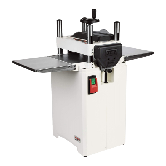
- Page 1 This .pdf document is bookmarked Operating Instructions and Parts Manual 15-inch Planer Models JWP-15B, JWP-15BHH JWP-15BHH JWP-15B 427 New Sanford Road LaVergne, Tennessee 37086 Part No. M-722150 Ph.: 800-274-6848 Edition 1 01/2019 www.jettools.com Copyright © 2019 JET...
-
Page 2: Important Safety Instructions
Do not use this planer for other than its intended 19. Make your workshop child proof with padlocks, use. If used for other purposes, JET disclaims master switches or by removing starter keys. any real or implied warranty and holds itself harmless from any injury that may result from 20. - Page 3 28. Remove loose items and unnecessary work WARNING: Drilling, sawing, sanding or pieces from the area before starting the machining wood products generates wood dust machine. and other substances known to the State of 29. Pay particular attention to instructions on California to cause cancer.
-
Page 4: Table Of Contents
6.2 Extension cords ............................10 7.0 Adjustments ..............................11 7.1 Belt tension/replacement .......................... 11 7.2 Replacing knives (JWP-15B only) ......................11 7.3 Replacing/rotating knife inserts (JWP-15BHH only) ................. 12 8.0 Operation ..............................12 8.1 Start switch ............................... 12 ... -
Page 5: About This Manual
If there are questions or comments, please contact your local supplier or JET. JET can also be reached at our web site: www.jettools.com. -
Page 6: Specifications
4.0 Specifications Table 1 Stock number 722150 722155 Model number JWP-15B JWP-15BHH Motor and Electricals Motor type Totally enclosed, fan-cooled, induction, capacitor start Horsepower 3 HP (2.2 kW) Phase Single Voltage 230 V only Cycle 60 Hz 11 A Listed FLA (full load amps) - Page 7 = not applicable The specifications in this manual were current at time of publication, but because of our policy of continuous improvement, JET reserves the right to change specifications at any time and without prior notice, without incurring obligations.
-
Page 8: Setup And Assembly
Cast iron extension tables (not shown) 6mm hex wrench (for JWP-15B only) Star point screwdrivers – F Torx point screwdriver T30 (for JWP-15B only) Knife inserts – G 13mm open-end wrench (for JWP-15BHH only) 10 Knife insert screws (not shown) -
Page 9: Handwheel
Connect a 4-inch dust hose to the port and secure Tighten hex cap screws (HP5). with a hose clamp. Visit JET’s website or contact your dealer for a complete line of dust collectors. Repeat for opposite extension table. -
Page 10: Levelers
The JWP-15B and JWP-15BHH are prewired for ordinances. 230V power only. The planer comes with a plug designed for use on a circuit with a grounded outlet that looks like the one pictured in Figure 6-1. -
Page 11: Adjustments
Figure 7-3 cutterhead. The following procedure will ensure a Snug the gib screws to secure the knife; do not proper setting of knives on the JWP-15B Planer. fully tighten yet. Disconnect machine from power source. Rotate cutterhead and repeat process for each Remove dust hood and top cover. -
Page 12: Replacing/Rotating Knife Inserts (Jwp-15Bhh Only)
CAUTION: Always remove hex wrench 11. Tighten all gib screws on the other two knives in the same fashion, until all gib screws on the before starting planer. cutterhead are firmly tightened. Before installing each screw, lightly coat the (NOTE: The purpose of this incremental screw threads with machine oil and wipe off any tightening process is to prevent any slight excess. -
Page 13: Depth Of Cut
Planer must be running when workpiece. The tension should be equal at both changing feed rate. Do not attempt to change ends of each roller. Note: Contact JET Technical feed speed while stock is passing through the Service before attempting any adjustments to spring machine. - Page 14 8.7.1 Outfeed roller height NOTE: This procedure uses a home-made gauge block and feeler gauges, which should be sufficient Disconnect machine from power source. for most planer operations. If more precise measurements are desired, use a dial indicator Remove top cover. device.
-
Page 15: Chip Deflector
8.7.2 Infeed roller height 9.0 Maintenance Use the identical procedure for checking the infeed roller as you did for the outfeed roller. Use the 0.032" Disconnect machine from (0.81mm) feeler gauge atop the gauge block. If power source before performing maintenance. adjustment is necessary, use the lock nut and screw on each end of infeed roller. -
Page 16: Belt Replacement
Reinstall drain plug (A) and fill gearbox with Push down or pull up the head assembly in the clean lubricant through hole (B). desired direction. Hold the assembly in position and retighten the cap screws. Install and tighten filler cap (B). Check table-to-cutterhead parallelism again as described in the previous section, then repeat steps 1 through 3 if needed until deviation is... -
Page 17: Lubrication Points
head casting; counterclockwise will decrease When adjustments are correct, replace chain the distance. This adjustment is very sensitive around corner sprocket, slide idler sprocket (S, and it should not be necessary to turn the Figure 9-3) back to re-tension chain, tighten bolt sprocket more than one or two teeth. -
Page 18: Troubleshooting Jwp-15B,15Bhh
10.0 Troubleshooting JWP-15B,15BHH 10.1 Performance problems Table 4 Symptom Possible Cause Correction Support long boards with an assistant Inadequate support of long boards. or extension rollers. Uneven feed roller pressure front to Adjust feed roller pressure. back. Snipe 15B: Sharpen or replace knives. -
Page 19: Mechanical And Electrical Problems
10.2 Mechanical and electrical problems Table 5 Symptom Possible Cause Correction * Knife projection from cutterhead is Adjust knife projection. Uneven depth of cut incorrect (15B only). side to side. Table not parallel to cutterhead. Adjust table/cutterhead parallelism. Board thickness does not match depth of cut Depth of cut scale is incorrect. -
Page 20: Replacement Parts
Non-proprietary parts, such as fasteners, can be found at local hardware stores, or may be ordered from JET. Some parts are shown for reference only, and may not be available individually. -
Page 21: Head Assembly - Exploded View
11.1.1 Head Assembly – Exploded View... -
Page 22: Head Assembly - Parts List
11.1.2 Head Assembly – Parts List Index No Part No Description Size 1 ....JWP15B-101 ..... Head ......................1 2 ....JWP15B-102 ..... Shaft ......................1 3 ....JWP15B-103 ..... Anti-Kickback Finger ..................37 4 ....JWP15B-104 ..... Collar ......................38 5 .... -
Page 23: Column Assembly - Exploded View
11.2.1 Column Assembly – Exploded View... -
Page 24: Column Assembly - Parts List
11.2.2 Column Assembly – Parts List Index No Part No Description Size 1 ....JWP15H-207 ..... Nut ......................... 4 2 ....TS-1490081 ....Hex Cap Screw ............M8-1.25Px45 ....5 3 ....JWP15H-204 ..... Column, Driving ..................... 1 4 .... -
Page 25: Cutterhead Assembly - Exploded View
11.3.1 Cutterhead Assembly – Exploded View 11.3.2 Cutterhead Assembly – Parts List Index No Part No Description Size ....JWP15B-CA ....Straight Knife Cutterhead Assembly (#1 thru #5) .......... 1 1 ....JWP15B-301 ..... Straight Knife Cutterhead ........15” ......... 1 2 .... -
Page 26: Gear Box Assembly - Exploded View
11.4.1 Gear Box Assembly – Exploded View... -
Page 27: Gear Box Assembly - Parts List
11.4.2 Gear Box Assembly – Parts List Index No Part No Description Size 1 ....JWP15B-401 ..... Gear Box Cover ..................... 1 2 ....TS-2246122 ....Socket Head Button Screw ........M6-1.0Px12 ....2 ....JWP15B-GBA ... Gear Box with Straight Cutterhead Assembly (#14 thru #45) .......... -
Page 28: Cabinet Assembly - Exploded View
11.5.1 Cabinet Assembly – Exploded View... -
Page 29: Cabinet Assembly - Parts List
23 ....5509069 ....Key, Dbl Rd Hd ............6x6x18mm ....1 24 ....JWP15B-524 ..... Motor Pulley ....................1 25 ....LM000372 ....Motor Label, JWP-15B..........3HP*230V*60HZ ... 1 26 ....TS-1550061 ....Flat Washer ............. M8 ......... 2 27 .... -
Page 30: Extension Table - Exploded View
11.6.1 Extension Table – Exploded View 11.6.2 Extension Table, Sheet Metal – Parts List Index No Part No Description Size ....JWP15B-SETA ..Steel Extension Table Assembly (#1 thru #3) ..........1 ....JWP15B-601 ..... Steel Extension Table ..................2 2 .... -
Page 31: Switch Assembly - Exploded View
11.7.1 Switch Assembly – Exploded View 11.7.2 Switch Assembly – Parts List Index No Part No Description Size ....JWP15B-SA ....Switch Assembly (#1 thru #13) ..............1 1 ....JWP15B-701 ..... Control Panel Kit .................... 1 ....JWP15B-SK ....Safety Key (not shown).................. 1 2 .... -
Page 32: Electrical Connections For Jwp-15B,15Bhh
12.0 Electrical Connections for JWP-15B,15BHH... -
Page 33: Warranty And Service
JET sells through distributors only. The specifications listed in JET printed materials and on official JET website are given as general information and are not binding. JET reserves the right to effect at any time, without prior notice, those alterations to parts, fittings, and accessory equipment which they may deem necessary for any reason whatsoever. - Page 34 This page intentionally left blank.
- Page 35 This page intentionally left blank.
- Page 36 427 New Sanford Road LaVergne, Tennessee 37086 Phone: 800-274-6848 www.jettools.com...
Need help?
Do you have a question about the JWP-15B and is the answer not in the manual?
Questions and answers