Table of Contents
Advertisement
Quick Links
Download this manual
See also:
User Manual
Advertisement
Table of Contents

Related Manuals for Tektronix Grass Valley 3000


Summary of Contents for Tektronix Grass Valley 3000
- Page 1 Installation and Service Grass Valley Model 3000 Video Production Switcher Software Release 5.3 071-0160-00 First Printing: December 1996 Revised Printing: February, 1998...
-
Page 2: Customer Support
The information in this manual is furnished for informational use only, is subject to change without notice, and should not be construed as a commitment by Tektronix, Inc. Tektronix assumes no responsibility or liability for any errors or inaccuracies that may appear in this publication. -
Page 3: Table Of Contents
Contents Important Safety Notices Symbols and Their Meaning in This Manual ..............Danger ............................. Warnings ..........................Cautions ..........................Power Cord Notices ......................North American Power Supply Cords ................ International Power Supply Cord ................EMC Regulatory Notices ...................... Section 1 — System Overview Introduction .......................... - Page 4 Contents Section 2 — Installation Introduction ..........................Unpacking ..........................Pre-installation Procedures ....................Items Required but not Supplied ................. Physical Specifications and Installation Requirements ..........Power Requirements ....................Environmental Characteristics ................Safety Requirements ....................Installation ..........................Model 3000-2 Control Panel Installation ..............Model 3000-2 Control Panel Console Dimensions ..........
- Page 5 Contents Powering Up .......................... 2-52 Preliminary Checks ......................2-52 Power-On ........................2-52 Redundant Power Supply Voltage Adjustments .............. 2-54 System Setup .......................... 2-56 Setting Vertical Blanking Range ................... 2-56 Setting Preview Blanking Switch ................. 2-56 Checking Auto-timed Analog Inputs ................2-58 What is Autotiming? ....................
- Page 6 Contents Section 3 — Functional Description Introduction ..........................System Configuration ......................System Overview ........................Signal Formats ........................ Analog Video ......................Timing ........................SMPTE Composite Parallel Digital ............... SMPTE Composite Serial Digital ................Input Clock (SYS1 CLK) .................. Clock (SYS2 CLK) .................... Input Fast Clock (IFCLK) ................
- Page 7 Contents Mix Effects Modules ...................... 3-34 Sync Generator and Preview Module ..............3-34 Sync Generator Section ..................3-36 Black and Test Generators Section ............... 3-36 Preview Section ....................... 3-37 Input Modules ......................3-38 Analog Composite Input 10-bit ................3-38 Composite Serial Digital Input ................3-40 Composite Parallel Digital Input ................
- Page 8 Contents Replacement of +5 Volt Power Supply Assembly ............. 4-12 Removal of Pioneer +5 Volt Supply ..............4-12 Installation of Todd +5 Volt Supply ..............4-14 Wiring Diagram ...................... 4-18 Redundant Power Supply Voltage Adjustments .............. 4-18 Replacement of Model 3000-2 Control Panel Power Supply(s) ....... 4-21 Replacement of Model 3000-3 Control Panel Power Supply(s) .......
-
Page 9: Symbols And Their Meaning In This Manual
Important Safeguards and Notices Important Safeguards and Notices Information on the following pages provides important safety guidelines for both Operator and Service Personnel. Specific warnings and cautions will be found throughout the manual where they apply, but may not appear here. Please read and follow the important safety information, noting especially those instructions related to risk of fire, electric shock or injury to persons. -
Page 10: Danger
Important Safeguards and Notices Danger Electrical potential is still applied to some internal components even when the power switch/breaker is in the off position. To prevent electrical shock when working on this equipment, disconnect the AC line cord from the AC source before working on any internal components. -
Page 11: Cautions
Important Safeguards and Notices To avoid fire hazard, use only components of the the specified type, voltage, and current rating as referenced in the appropriate parts list for this equipment. Always refer fuse replacement to qualified service personnel. To avoid explosion, do not operate this equipment in an explosive atmosphere unless it has been specifically certified for such operation. -
Page 12: Emc Regulatory Notices
Important Safeguards and Notices EMC Regulatory Notices Federal Communications Commission (FCC) Part 15 Information This device complies with Part 15 of the FCC Rules. Operation is subject to the following two conditions: (1) This device may not cause harmful interference. (2) This device must accept any interference received including interference that may cause undesireable operations. -
Page 13: Section 1 - System Overview
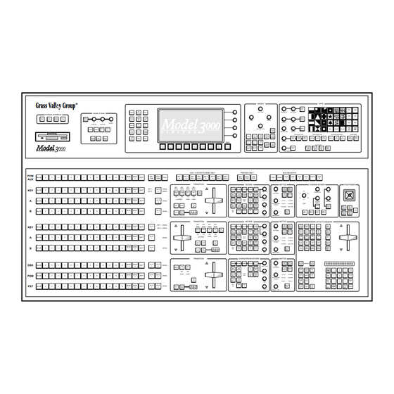
System Overview Introduction This section presents a general description of the Grass Valley Group Model 3000 Switching Systems, their basic architecture, and a list of their video specifications. System Description The Model 3000 is a multi-format digital switcher that can manipulate a variety of composite digital and analog video and key signals through the use of 10-bit digital processing. - Page 14 Section 1 – System Overview The Model 3000-3 switcher, Figure 1-2, provides 3 mix/effects systems, a Program/Preset mixer with Dual Downstream keyer, and up to 48 video inputs and 48 key inputs at a time from the control panel. Figure 1-2. Model 3000-3 Control Panel The Control Panel has a user-friendly layout and shallow menu structure that allows quick and easy control of operating characteristics and signal manipulations.
-
Page 15: Available Options
Available Options INPUTS OUTPUT Video/Key Video/Key MIX/EFFECTS Signals In Signals Out CROSS- PROCESSORS EXPAN- POINTS SION Status Terminal MIX/EFFECTS LOGIC CONTROLLER/ CONTROL MAIN PANEL PROCESSOR Frame Signal Panel Processor Link Frame CONTROL PANEL POWER SUPPLY Signal Processor Power Supply Control Panel Figure 1-3. -
Page 16: Output Modules
Section 1 – System Overview Output Modules Output module types can also be inter-mixed to suit your needs. Each module type supports four channels, with up to three outputs per channel, depending on the format. The following module types are available: Analog Composite Output (4 signals;... -
Page 17: Frame Store
Available Options Frame Store The Frame Store option allows storage and retrieval of images at a 10-bit resolution. A maximum of one four-field video and one four-field key can be frozen in Frame Store. Video and Key inputs may be frozen together or independently. -
Page 18: Dual Chroma Keyer
Section 1 – System Overview Dual Chroma Keyer Each Dual Chroma Keyer module can chroma key two analog component or composite inputs. One Dual Chroma Keyer module is used with each M/E. The following component formats are supported: Betacam ® Dual Chroma Keyer modules are installed in the middle bay of the Signal Processor frame. -
Page 19: Borderline Key Edge Generation
Available Options Borderline Key Edge Generation Borderline Key Edge Generators are optional for each keyer in the switcher. The Borderline option is added by plugging a small submodule onto the Keyer module of an M/E. One module can be installed for each of the two keyers in each M/E and one in each of the two keyers of the Downstream Keyer (DSK) module. -
Page 20: Safe Title/Action Area Generator
Section 1 – System Overview Safe Title/Action Area Generator The Safe Title/Action Area Generator option provides up to four different patterns that can be superimposed on the switched preview output of the switcher. It may be used to define a safe title area, safe action area, or for screen centering and horizontal/vertical alignment of picture elements. -
Page 21: Power Supplies
Available Options Power Supplies The Model 3000 is powered by two power supply assemblies. One assembly located inside the control panel tub supplies the Control Panel, and a larger 19” rack-mounted power supply powers the Signal Processor frame. Optional redundant power supply assemblies are available for both the Control Panel and the Signal Processing frame. -
Page 22: Physical Description
Section 1 – System Overview Physical Description Model 3000 electronic circuitry is contained on circuit modules and boards in the Signal Processor Frame and Control Panel. Control circuitry is located in the Control Panel and in the middle bay of the Signal Processor frame. - Page 23 Physical Description Impeller Fan — Air flows up through the frame Outlets (Both sides & Rear) Front Door Output Modules and Options (Bay A) Control and Signal Processing Modules (Bay B) Input Modules and Options (Bay C) Air Inlets Air Filter are on both sides Power Supply Assembly Slide is Mounted directly...
-
Page 24: System Specifications
Section 1 – System Overview System Specifications Specifications for the NTSC version of the Model 3000 Systems are listed on the following pages. Refer to Section 2, Installation and Configuration, for information on the mechanical characteristics of the system. Specifications are provided in the following areas: Power Specifications Analog Input Characteristics... - Page 25 System Specifications Table 1-1. Analog Input Video Specifications Characteristic Requirement Video Amplitude For Primary Inputs 1 Volt p-p Nominal (composite) Maximum Video Excursion +138 IRE peak positive Relative To Blanking - 42 IRE peak negative (before clipping) Video Amplitude For Color Luminance: 1 V p-p Without Setup Difference Chroma Key Inputs Color Difference: ±...
- Page 26 Section 1 – System Overview Table 1-2. Digital Input Video Specifications Input Type Specification Parallel Complies with ANSI T14.22/082A and ANSI T14.22/081B Serial Complies with ANSI T14.22x2131D Table 1-3. Parallel Digital Input Characteristics Characteristics Specification Connector 25 Pin Female D Type with Screw Locks. 110 Ω...
- Page 27 System Specifications Table 1-5. Analog Output Characteristics Characteristic Specifications Output Amplitude 1.0 Volt p-p nominal DC On Output Blanking Level < 50 mV Output Return Loss > 40 dB to 5 MHz Output Isolation > 40 dB to 5 MHz Output SC/H Phase <...
- Page 28 Section 1 – System Overview Table 1-7. Serial Digital Output Characteristics Characteristic Specifications Output Format Complies with ANSI T14.22/082A and ANSI T14.22/081B Aux Data TRS and Line ID only 75 Ω BNC Connector 75 Ω Output Impedance Return Loss > 15 dB 5MHz to 270 MHz Output Amplitude 1.8 V±...
- Page 29 Section 1 – System Overview Table 1-9. Video System Characteristics (Analog and Digital) Characteristic Specifications Adjustable 9.9 µS to 11.0 µS Blanking Width Number Of Quantization Bits 10 Minimum Mix Tracking Error Linearity During Mix Linearity Is Not Affected By Mix Frequency Response During Mix Response Is Not Affected By Mix Path Length...
- Page 30 Section 1 – System Overview 1-18...
-
Page 31: Introduction
Installation Introduction This section describes the physical installation of a Model 3000 Digital Switcher. The process of installing the Model 3000 is discussed in the following major areas: Unpacking Installing the Control Panel Installing the Signal Processor Frame in the rack Installing the Power Supply for the Signal Processor Frame Cabling the equipment Connecting power... -
Page 32: Unpacking
Section 2 – Installation Unpacking The Model 3000 is packaged in several boxes — one each for the following: One containing the Signal Processor Frame One containing the Model 3000-2 Control Panel, panel cable, power cord, spare fuse kit, lens chips, and diagnostic probe. Or two boxes containing the Model 3000-3 Control Panels;... -
Page 33: Pre-Installation Procedures
Items Required but not Supplied Pre-installation Procedures Before you physically install the Model 3000, familiarize yourself with this section covering required tools, physical specifications, and power requirements. Items Required but not Supplied These items are required for installation but not supplied by Grass Valley. Medium flat-bladed screwdriver Medium Phillips-head screwdriver #10, #15, and #20 Torx screwdrivers... -
Page 34: Power Requirements
Section 2 – Installation P ow e r Re qui re m e nt s Power requirements for the Model 3000 Control Panel and Signal Processor Frame are listed in Table 2-2. Table 2-2. Model 3000 Power Specifications Component Power Voltage Frequency Model 3000-2 Control Panel... - Page 35 Physical Specifications and Installation Requirements WARNING The Signal Processor frame power supply assembly exhibits high leakage (fault) currents due to the EMI suppression filter system. This power supply chassis must be connected to earth ground via the ground wire provided in the AC input cord.
-
Page 36: Installation
Section 2 – Installation Installation The following procedures contain the instructions for installing the Control Panel, Signal Processor Frame, and Frame Power Supply. Procedures are included for circuit modules and cable installation. Before proceeding, read all precautions and notes. Model 3000-2 Control Panel Installation This installation does not require countersunk or beveled edges. - Page 37 Model 3000-2 Control Panel Installation Primary Redundant Power Supply Power Supply Interconnect Cable Area Cable Area Cable Area 2.68" 4.82" 8.26" 13.54" (6.81 cm) (12.25 cm) (21.0 cm) (34.4 cm) Rear Limits of Cutout Model 3000-2 Control Panel Area 24.00" (60.96 cm) Front 41.25"...
-
Page 38: Inserting The Model 3000-2 Panel
Section 2 – Installation 25.1" (63.8 cm) 6.15" (15.6 cm) 13.53" (34.4 cm) 1.125" 7.38" (2.9 cm) 5.3" (18.8 cm) (13.5 cm) 25.41" (64.5 cm) Figure 2-2. Model 3000-2 Control Panel Profile I ns e rt i ng t he M ode l 3 00 0 -2 P a ne l 1. -
Page 39: Model 3000-3 Control Panel Installation
Model 3000-3 Control Panel Installation Model 3000-3 Control Panel Installation A full flush-mount installation requires countersunk edges. The Panel enclosures (upper and lower tubs) slip into the cutout from the top, are fitted into the routed openings, and secured by 27 screws inserted through overhanging flanges at the front, rear, and sides of the tubs. - Page 40 Section 2 – Installation 0.375" (1.0 cm) 0.50" (1.25 cm) 9.50" (24.1 cm) 10.2 " (25.9 cm) 0.375" (1.0 cm) 0.2" (0.5 cm) 6.50" (16.5 cm) 3.625" 4.157" 0.375" 0.22" (9.2 cm) (10.6 cm) (1.0 cm) (0.5 cm) 17° 8.625" (21.9 cm) 0.50"...
-
Page 41: Model 3000-3 Control Panel Console Dimensions
Model 3000-3 Control Panel Installation M ode l 3 0 0 0 - 3 C ont rol P a nel Cons ole D im en sio n s These instructions allow you to install your Control Panel in a full flush- mount installation. - Page 42 Section 2 – Installation 53.125" (134.8 cm) .5" by .375" Notch .5" by .375" Notch (1.25 by 1.0 cm) (1.25 by 1.0 cm) Rear 0.375" 0.375" (1.0 cm) (1.0 cm) Limits of Upper Control Panel Cutout 9.625" Area (23.5 cm) 0.188"...
- Page 43 Model 3000-3 Control Panel Installation 3. Route a 3/8” (9 mm) by 3/16” (4.5 mm) lip on the lower edge of the cutout as illustrated in Figure 2-6. Optional Interconnect Interconnect Cable Area Cable Area 2.5" 2.0" 8.125" 7.125" (6.4 cm) (5.1 cm) (20.6 cm) (18.1 cm)
-
Page 44: Inserting The Model 3000-3 Panels
Section 2 – Installation 4. Carefully place the Upper Control Panel into the cutout and mark pilot hole locations for the 12 anchor screws. WARNING Do not lift the Control Panel by the handles or the transition lever arms. Always lift the Control Panel by holding onto the tub. 5. -
Page 45: Signal Processor Frame Installation
Signal Processor Frame Installation Signal Processor Frame Installation The Signal Processor Frame must be installed before either of the power NOTE: supplies. When planning your installation, ensure that the frame will be installed high enough in the equipment rack to allow room (7 rack units) for the installation of the Frame Power Supply below it (plus another 7 rack units if an optional Redundant Power Supply is to be installed). - Page 46 Section 2 – Installation 1. Ensure that all packing foam, strapping, and tape is removed from the frame before installing the frame in the rack. The frame is shipped with a protective metal pan on the bottom. Leave the NOTE: pan in place to protect the power cables until the frame is mounted in the rack.
- Page 47 Signal Processor Frame Installation Signal Processor Frame Front Secure Bolts through Frame (8 each side) into Rack Note: Front Door Not Shown For Clarity Leave enough space below Signal Processor Frame for mounting Frame Power Supply and (optional) Redundant Frame Power Supply (7 RU/12.25 in./311 mm per supply).
-
Page 48: Signal Processor Frame Power Supply Installation
Section 2 – Installation Signal Processor Frame Power Supply Installation The Primary Power Supply must be mounted immediately below the Signal Processor Frame in the rack. If you are installing an optional Redundant Power Supply, it must be located immediately below the Primary Power Supply. - Page 49 Signal Processor Frame Power Supply Installation In the following descriptions, the terms “right” and “left” refer to the NOTE: locations of components as viewed from the rear of the power supply. 5. Remove the right and left covers from the rear of the Power Supply assembly to expose the wiring connections.
- Page 50 Section 2 – Installation If you will be installing a Redundant Power Supply at this time, skip Steps NOTE: 11 through 13 and perform with Step 14. Also skip Step 15 for now. 11. Connect the two large black cables running down from the right rear of the Signal Processor Frame to the right post (see Figure 2-10) and...
-
Page 51: Redundant Power Supply Installation
Redundant Power Supply Installation Redundant Power Supply Installation The Redundant Power Supply Option consists of the following components: Power Supply Chassis (identical to the Frame Power Supply) Pair of Red cables Pair of Black cables 2 studs 2 lock washers WARNING To reduce the risk of electric shock, do not perform any servicing other than that contained in the operating instructions unless you are qualified to do so. - Page 52 Section 2 – Installation Signal Processor Red Cables from Processor Lock Primary Washers Power Supply Nuts Black Cables from Processor If Present, Remove Lock Washers Connector Studs Cover Plate If Present, From Primary Power Supply Remove Slot Cover Plate From Primary Power Supply Route Cables Down Through...
-
Page 53: Review
Review 8. Place the pair of new black cables over the proper studs in the Primary and Redundant Power Supplies, routing the cables through the slot in the bottom of the Primary Supply and the top of the Redundant Supply. (The colors must match those of the existing cables.) The black cables must go in the slot before the red cables;... -
Page 54: Module Locations
Section 2 – Installation Module Locations The following information on input, processor, and output modules and their associated Interconnect Adapters is not critical for installation of a Model 3000 that has been shipped with modules already installed. It is provided here for reference. The modules that slide into the frame from the front plug into connectors inside the frame. - Page 55 Input Modules Options Card Cage (Outputs) Bay A Cell # Middle Card Cage Bay B Cell # Options Bottom Card Cage (Inputs) Bay C Figure 2-12. Signal Processor Frame Module Locations (front view) 2-25...
-
Page 56: Output Modules
Section 2 – Installation Output Modules Three types of output modules can be intermixed to suit your needs. Each of the modules supports four channels, with up to three outputs per channel, depending upon the format. The following types of output modules are available: Analog Composite Output (4 channels: 3 outputs per channel) Parallel Digital Output (4 channels: 1 output per channel) - Page 57 Interconnect Adapters Input Interconnect Boards R/R-Y B/B-Y Analog Inputs Serial Digital use 50-ohm R/R-Y uses 75-ohm BNC Connectors and 75-ohm Cables BNC Connectors and 75-ohm Cables B/B-Y Mounts in Top (Output) Section of Processor Frame Serial Input Parallel Input Analog Input Component Analog Chroma Key Input (Dual RGB Input)
- Page 58 Section 2 – Installation Uses 50-ohm Uses 75-ohm BNC and BNC and 75-ohm 75-ohm Cable Cable NOTE: The Tally Output Interconnect Adapter is installed in the Input section of the Frame Card Cage. Parallel Digital Analog Composite Serial Digital Tally Output Output Module Output Module Output Module...
-
Page 59: Rf/Emi Strips On Input/Output Modules
Interconnect Adapters R F/E M I S t ri ps on I n put /Out put M odules RF/EMI strips on each adapter, see Figure 2-15, are designed to control RF/EMI emissions. As each adapter is installed in the frame, these strips make contact with the next adapter to the right. -
Page 60: Cable Connections
Section 2 – Installation Cable Connections This section details the cabling of the Model 3000 system components. While it is not necessary to follow the steps in the specific sequence presented, the procedures given provide a reference for ensuring that all connections are properly made. -
Page 61: Model 3000-2 Control Panel Control Connections
Model 3000-2 Control Panel Control Connections Model 3000-2 Control Panel Control Connections 1. Connect the interconnect control cable to the connector marked J1 on the rear of the Control Panel as shown in Figure 2-16. 2. Connect the other end of the interconnect control cable to J3 on the Communications Panel at the rear of the frame. -
Page 62: Model 3000-3 Control Panel Connections
Section 2 – Installation Model 3000-3 Control Panel Connections 1. Connect the interconnect control cable (Frame Communication) to the connector marked J105 on the rear of the upper Control Panel as shown Figure 2-16. 2. Connect the Frame Communication cable from the rear of the upper Control Panel (J105) to J3 on the Communications Panel at the rear of the Signal Frame. - Page 63 Model 3000-3 Control Panel Connections Status Terminal Pointing Device Frame Communication DB-25 DB-25 DB-25 Connector Connector Connector (J103) (J104) (J105) Rear of Upper Panel Tub J101 J102 INTERCONNECT Rear of Lower Panel Tub AC Input AC Input Communication Link Power Power between Control Panel Connector...
-
Page 64: Input Signal Connections (Video And Key)
Section 2 – Installation Input Signal Connections (Video and Key) The Model 3000 allows up to 64 video/key inputs at a time to be connected. These inputs are connected to the Input Modules through the Interconnect Adapters installed at the rear of the frame. Each Input Module supports four analog composite or digital video inputs. -
Page 65: Parallel Digital Connections
Input Signal Connections (Video and Key) P a ra l l e l Di gi t a l Conne c ti ons The parallel digital input cables consist of 12 twisted pairs, a common drain wire, a braided or foil shield in contact with the drain wire, and two male 25-pin D-Type connectors. -
Page 66: Reference Input Connections
Section 2 – Installation Reference Input Connections 1. Provide analog Black Burst (Color Black) to one of the REFERENCE INPUT connectors (J1 and J2) on the Communications Panel. 2. Terminate the loop-through reference signal connections as necessary. Output Signal Connections Analog Video and Key output signals from the Model 3000 may be connected directly to external devices. -
Page 67: Frame Communications Connections
Frame Communications Connections Frame Communications Connections The Model 3000 includes provisions for GPI triggers and for connecting to Kaleidoscope, Krystal, the DPM-700, other Digital Effects devices, Video Production Editors, and a Tally Expansion chassis. Communication to these devices is provided via connectors located at the rear of the Model 3000 frame as shown in Figure 2-20. -
Page 68: Gpi Connections
Section 2 – Installation G PI Conne c t ions The four GPI connectors on the rear panel of the Signal Processor Frame provide eight input and eight output GPI connections (see Figure 2-21). These connections provide a variety of user-assignable GPI applications such as remote control of Auto Transitions, DSK mix, Fade-to-Black Transitions and other selected functions. -
Page 69: Gpi Outputs
Frame Communications Connections G P I O ut put s Each GPI output consists of a pair of connections on the rear of the frame, which are connected to an isolated pair of relay contacts (SPST; normally open). These pairs of output connectors are numbered 1 through 8 with a chassis ground connection on both ends of each connector module. -
Page 70: Connecting To Kaleidoscope
Section 2 – Installation C onne c t i ng t o Ka l e idosc ope The Kaleidoscope Controller connects to the Model 3000 through an adapter cable (151022-00) and the Model 3000 RS-422 control cable (054602-16). See Figure 2-22. -
Page 71: Connecting To A Krystal Digital Picture Manipulator
Frame Communications Connections When Kaleidoscope’s outputs are sent to an Output Router, the Primary Video and Key and Secondary Video and Key outputs may be connected to any four analog inputs on the Model 3000. The Model 3000’s inputs are assigned via menus to any crosspoints (Map Inputs Menu under the Inputs Menu). - Page 72 Section 2 – Installation C onne c t i ng t o a D P M -7 0 0 The Model 3000 can initiate E-MEM Effects Memory Learn and Recall operations in a Grass Valley DPM-700 using Peripheral Bus II protocol. In addition, the Model 3000 can trigger specific functions in the DPM.
-
Page 73: Dpm Logical Channel Tally
Frame Communications Connections The standard length of the control cable between the Model 3000 and the DPM-700 is 16 meters (P/N 054602-16). Alternatively, you may make your own cable as illustrated in Figure 2-24. Maximum length of the control cable is 300 meters. Male Male (Wiring... -
Page 74: Dpm Logical Channel Tally Example 1
Section 2 – Installation DP M Logic a l Cha nnel Ta ll y E xa m p le 1 This example demonstrates an appropriate tally for a “near/far switching” configuration. The following diagram illustrates the video wiring required for this example. Switcher Signal Processor Frame DPM-700... -
Page 75: Dpm Logical Channel Tally Example 2
Frame Communications Connections DP M Logic a l Cha nnel Ta ll y E xa m p le 2 This example demonstrates an appropriate tally for a “double-box” configuration, where the two DPM-700 channels are combined and are returned to the switcher. The following diagram illustrates the video wiring required for this example. -
Page 76: Dpm Logical Channel Tally Menu Setup
Section 2 – Installation DP M Logic a l Cha nnel Ta ll y M e nu Setu p After connecting the DPM as shown previously in example 1 or example 2, make the following selections in the 3000 menus. 1. -
Page 77: Power Connections
Connecting the Control Panel to the AC Power Source Power Connections Connecting the Control Panel to the AC Power Source The present Control Panel Power Supply is capable of operating on either 110 Vac or 220 Vac nominal (see Table 2-2 for specifications.) This supply is auto-ranging;... -
Page 78: For 110-Volt Operation
Section 2 – Installation CAUTION To reduce the risk of electrical shock, ensure that a valid ground is present. For redundant supply systems, connect the power supplies to separate branch circuits employing separate service grounds. 1. Ensure that the power switch located on the front of the Frame Power Supply is in the Off (0) position. - Page 79 Connecting the Frame Power Supply to the AC Power Source 3. In the center section, disconnect the incoming AC power wires from the left and right sides of the terminal block (see Figure 2-29). Remove 10 AWG Remove Power Cord Nut and (3 wires) and Jumper...
- Page 80 Section 2 – Installation 7. The 6 AWG wiring may now be installed (see Figure 2-30). It is suggested that a 3/4-inch (19 cm) electrical conduit fitting be installed in the hole from which the power cord retention block was removed and the wiring be routed in through flexible conduit from a junction box.
- Page 81 Connecting the Frame Power Supply to the AC Power Source 11. Inspect your work to make sure that all connections are correct, tight, and safe. 12. Reinstall the center cover plate, putting in the four screws at the top and the three screws at the bottom. 13.
-
Page 82: Powering Up
Section 2 – Installation Powering Up The following pages provide you with the information necessary to turn on and begin operating the Model 3000 Production Switcher. Preliminary Checks Before bringing the system on-line, the following preliminary checks need to be made: CAUTION You should observe normal precautions when working around high current, low voltage power supplies. - Page 83 Power-On The Control Panel Menu Display is on and displaying the Grass Valley sign-on message. Some pushbuttons are lit on each area of the Control Panel. To meet RF/EMI specifications and to ensure proper cooling, the door on NOTE: the front of the Signal Processor must be closed. Maintenance personnel should be familiar with the Control Panel and its usage.
-
Page 84: Redundant Power Supply Voltage Adjustments
Section 2 – Installation Redundant Power Supply Voltage Adjustments If you ordered a redundant Frame Power Supply with the Model 3000, it was tested and adjusted with the system before leaving the factory. In this case, it is not necessary to perform the following procedure. If a redundant Frame Power Supply is ordered after the Model 3000, the following procedure should be performed to ensure that the Primary and Redundant supplies are working properly together. - Page 85 Power-On Test Points –5V +13V –13V +48V Measure +5V Between These Lugs High Current +5V ADJ +48V +5.2V –13V +13V Figure 2-31. Voltage Test Points and Adjustments on Todd Power Supplies 4. Turn off the Primary Power Supply, then turn on the Redundant Supply and measure its voltages.
-
Page 86: System Setup
Section 2 – Installation System Setup Setting Vertical Blanking Range Table 2-4 details the possible end positions of the vertical blanking interval (see Figure 2-32 on the next page). To select any endpoint, simply turn the 16-position rotary switch (S6) located at the front of the Sync Generator module to the switch setting that corresponds to the desired value. - Page 87 Setting Preview Blanking Switch Sync Generator Module (front of module facing front door) Middle of Cardcage, Cell B7 Vernier Fine Switcher Timing Medium Coarse V Blanking Start End (set by S6) Vertical Blanking Interval Must be set down (OFF) for Normal V Sync Operation 0 F E D C B A 9 8 7 6 5 4 3 2 1...
-
Page 88: Checking Auto-Timed Analog Inputs
Section 2 – Installation Checking Auto-timed Analog Inputs Analog input modules with autotiming have four sets of front mounted LEDs. Each set of three LEDs reflects the current state of an input channel arriving at the module. LEDs are marked as follows: NO BURST Subcarrier NO SYNC... -
Page 89: Installation Of Options
Crosspoint Name Displays (Model 3000-3 only) Installation of Options The following pages describe installation of several options. If you are not installing any of these options at this time, turn now to “Configuring Your System Software” at the end of this section. Crosspoint Name Displays (Model 3000-3 only) The Input Display Board Option is installed in the Upper Control Panel of the 3000-3 switcher . -
Page 90: Tally Output Option
Section 2 – Installation 5. Next, install the middle Display Board, followed by the right Display Board (similar to steps 3 and 4). 6. Take the “long length” ribbon cable and attach one connector to the left Display Board socket (the connector and socket are keyed). Connect the second ribbon cable connector to socket J2 of the Control Panel CPU Board (068985). -
Page 91: Tally Output Module Switch Settings
Tally Output Option Ta l ly O ut put M odule Swi tc h S e tt ings The 068932 Tally Output module mounts in slot 17 of Bay C in the switcher frame. Seven banks of eight DIP switches on the module determine how the module will act on the data sent to it. - Page 92 Section 2 – Installation RESET INCOMING DATA NORMAL ON-AIR TALLY= ALL SWITCHES OFF. REFER TO MANUAL FOR OTHER MODES. REMOVE JUMPER TO ISOLATE TALLY COMMON A AND TALLY COMMON B Figure 2-34. Tally Output Module Switch and Jumper Location When Mode 4 (Individual Bus Iso Tally) is selected, the remaining six banks of switches on the board (INDIVIDUAL BUS ENABLES 1-48) select the switcher’s internal buses to be used as tally sources (see Table...
- Page 93 Tally Output Option Table 2-6. Tally Bus Enables Switch Settings Segme Module Segme Module Function Function nt # Label nt # Label † PGM Video Bus M/E 3 Key 1 Video Bus † PGM Key Bus M/E 3 Key 1 Key Bus †...
-
Page 94: Tally Output Connector Pinouts
Section 2 – Installation Ta l ly O ut put Conne ct or P inouts The two tally output connectors on the 068941 board are female 37-pin D connectors labeled J1 and J2. Pinouts for the two connectors are shown in Figure 2-35. -
Page 95: Tally Expansion Option
Tally Expansion Option Tally Expansion Option The Tally Expansion Option provides expansion of the tally output function provided by the Tally Output Option described previously. The Tally Expansion Option consists of a 2 Rack Unit (2 RU) chassis which has two (redundant) power supplies mounted on a single sled and three slots for Tally Output modules (068932), and a 16 meter control cable. -
Page 96: Chassis Installation
Section 2 – Installation C ha s s i s I ns t a l l a t ion Refer to Figure 2-36. 1. Install the rear supports on the chassis. 2. Install the rear support brackets into the rack. 3. -
Page 97: Control Cable Installation
Tally Expansion Option C ont r ol Ca ble I ns t a lla t ion Each Tally Expansion chassis comes with a 16 meter (50 foot) cable. This cable has a 9 pin D connector on each end. The cables are standard RS422 and can be replaced with a custom-built cable if desired. -
Page 98: Tally Output Cable Installation
Section 2 – Installation If there is more than one Tally Expansion chassis, do the following steps: 1. Connect the second cable to J4 on the rear of the first chassis. 2. Run that cable to the next Tally Expansion chassis. 3. -
Page 99: Setting Tally Module Switches
Tally Expansion Option S e t t ing Ta l l y M odule Swi tc he s Seven banks of eight DIP switches on each of the Tally Modules determine how that module will act on the data sent to it. The settings of these switches are described under “Tally Output Option,”... -
Page 100: Optional Remote Aux Control Panels
Section 2 – Installation Optional Remote Aux Control Panels Optional Remote Aux Control Panels allow you to control the switcher aux buses from a remote location. Three models of Remote Aux Panels are available, each identified by the number of rack units (RUs) it occupies in the equipment rack. -
Page 101: Minimum Requirements
Optional Remote Aux Control Panels The three RU panel (Figure 2-40) has large buttons and is designed for locations where it is desirable to operate more than one bus. This panel will normally control all aux buses but can be set up to lock out specific buses. -
Page 102: Joystick Override
Section 2 – Installation J oy s t ic k O v e rri de Each panel has inputs for up to 8 external user-supplied switch closures to enable the override. The aux bus switches to a user-defined crosspoint selection when the switch is closed. When the switch is released, the aux bus returns to its previous selection. -
Page 103: Switcher Interconnect Cable
Optional Remote Aux Control Panels Lay the cable from the switcher frame to where the first Remote Aux Panel will be. Allow enough cable to reach the control panel connector, and about 3 feet (1 meter) extra, then cut the cable and strip the wires. S w i t c he r I nt e rc onne ct Ca bl e The switcher interconnect cable that plugs into the Remote Aux Panel has screw clamps to hold the wires. -
Page 104: Joystick Override Cable Installation
Section 2 – Installation J oy s t ic k O v e rri de Ca ble Ins ta ll at ion A user-fabricated cable, external switches, and a 9-pin subminature D connector with 4-40 jackscrews are required to implement the joystick override. -
Page 105: Setting Rear Panel Switches
Optional Remote Aux Control Panels S e t t ing Re a r P a ne l S wit c hes The rear panel includes a number of switches that control operating modes, such as address, bus enable, delegate enable, and test mode. Settings of these switches are explained below. - Page 106 Section 2 – Installation FORCE HIGH TALLY PANEL ADDRESSES BUS TO BE CONTROLLED * Panel Addresses 32 and 64 Must be Set To Off DC POWER COMMUNICATIONS JOYSTICK – OVERRIDE SHIELD DC POWER COMMUNICATIONS JOYSTICK – OVERRIDE SHIELD DC POWER COMMUNICATIONS JOYSTICK –...
-
Page 107: Delegate Lock Switch
Optional Remote Aux Control Panels De l e ga t e Loc k S wit c h On the one and two RU panels, the DEL LOCK switch has no meaning. On the three RU panel, the DEL LOCK switch controls the functioning of the aux buses that have BUS ENABLE switches OFF: DEL LOCK Switch OFF: If a BUS ENABLE switch is OFF, the associated Delegate button on the panel can be selected and the source button... -
Page 108: Remote Aux Panel Lens Chip Installation
Section 2 – Installation Figure 2-44. Remote Aux Panel Power Supply 4. After all panels have been connected, plug the D connector of the communications cable into the AUX BUS CONTROL connector on the back of the switcher frame. 5. Plug the power supply of each Remote Aux Panel into a source of power (100 to 120 Vac or 200 to 240 Vac). - Page 109 Optional Remote Aux Control Panels Clear Overcap Lens Designation Chip Lens Figure 2-45. Lens Chip Installation 2-79...
-
Page 110: Mask Draw Tablet Installation
Section 2 – Installation M a s k Dra w Ta bl e t I nst a lla t ion The new Mask Draw feature allows you to use a graphics tablet (connected to the switcher Control Panel), to customize existing masks, or create new ones. -
Page 111: Installation For Sd Series
Optional Remote Aux Control Panels On a Model 3000-2: a. Open the Control Panel lid and locate the Control Panel CPU Board. Locate jumper blocks (2-pins each), labeled J3 and RS-232, at the top, middle, of the board. Set the blocks to the “= DCE” setting. On a Model 3000-3: b. -
Page 112: Configuring Your System Software
Section 2 – Installation Configuring Your System Software You have now completed the hardware installation and verification of your Model 3000 Switcher. The system must now be configured through the Configuration menu for use with the signal and equipment connections in your facility, and for your operational preferences. -
Page 113: Troubleshooting
Optional Remote Aux Control Panels Troubleshooting The Model 3000 includes some diagnostic and system status indicators that may be helpful in isolating simple problems during the start-up process (see Table 2-8). These not intended for detailed servicing, but rather as a “quick check” of hardware and software problems that might be encountered during power-on and initial system configuration. - Page 114 Section 2 – Installation 2-84...
-
Page 115: Introduction
Functional Description Introduction The Model 3000 Switcher consists of three main areas. Signal Processor Frame Control Panel Frame power supply chassis Each of these areas is explored in detail in this section. This section will provide you with enough knowledge of the basic system that you can confidently perform any needed service and diagnostic procedures. -
Page 116: System Configuration
Section 3 – Functional Description System Configuration As described in Section 1, a Model 3000 system consists of a Control Panel, a Signal Processor Frame and a Power Supply for each unit. Various options may be added to the basic system to increase functionality. A typical system may have several options such as Secondary Wipe Generators, Expanded Communications, and Redundant power supplies. -
Page 117: System Overview
System Overview System Overview This section details the basic functions of a Model 3000 Switcher. Figure 3-1 shows a typical intermediate sized switcher system. Composite analog input signals are processed and converted to 10-bit digital values via A/D converters in the input circuitry. (All values are internally routed and manipulated as 10-bit values after the input stage.) Composite digital inputs may be serial or parallel. - Page 118 Section 3 – Functional Description Dual Chroma Dual RGB Inputs Keyers Option Video Signals Input M/E Keyers Modules M/E 1, M/E 2 80 x 48 Video Key Signals & M/E 3 Crosspoint Matrix Clocks, Black, Background, Sync Generator and Test Signal Generators Mask Bus and Framestore Video...
- Page 119 System Overview Secondary Wipe Option To Framestore M/E Mixers Effects Loop Crosspoints M/E 1, M/E 2 & M/E 3 M/E and DSK Program Video and Key Outputs Preview Video Mask Program Video and Key Switched Preview DSK Program Video and Key M/E Preview (for each M/E) Output Mask, M/E and DSK...
-
Page 120: Signal Formats
Section 3 – Functional Description Signal Formats A na l og V i de o As mentioned previously, the switcher accepts input analog video signals in NTSC composite (depending on the model you have). It also accepts Chroma Key signals in composite or RGB component, SMPTE/EBU YUV component, and Betacam®... -
Page 121: Smpte Composite Serial Digital
System Overview S M P TE Compos i t e S e ri al Di git al Composite Serial Digital signals are basically the same as parallel data , except data is sent out one bit at a time instead of one word at a time. Data is shifted out serially in an encoded order. -
Page 122: Input Clock (Sys1 Clk)
Section 3 – Functional Description The following clocks are generated on the Sync Generator/Preview Module (bay B, cell 15) and are used throughout the Signal Processor frame for timing: I nput C loc k ( S YS 1 CLK) A clock used for timing data into the demultiplexor circuits. It runs at four times the speed of the subcarrier. - Page 123 System Overview 10-bit 10-bit A Data Register Multiplexer Output 10-bit B Data to Bus OFCLK Multiplexer 10-bit Register A Data 10-bit Bus Demultiplexer 10-bit Register B Data IFCLK Demultiplexer Figure 3-3. Multiplexer and Demultiplexor Circuits. ICLK A Data into Mux (CLK) B Data into Mux (CLK) IFCLK, OFCLK Bus (Mux Register Out —...
-
Page 124: Input And Output Signals
Section 3 – Functional Description Input and Output Signals Input Modules Up to four sets of video signals can be applied to each Input Module, of which there are three types: Analog 10-bit Auto-timing Input Module Composite Digital Bit-parallel Input Module Composite Digital Bit-serial Input Module A na l og 1 0 - bi t Aut o- ti ming Input M od u le Four inputs (video or key) can be input to the module. -
Page 125: Output Modules
Input and Output Signals Output Modules Regardless of whether input signals are analog or digital, the Signal Processor Frame processes the signals according to instructions from the Control Panel, and provides any outputs you have specifically purchased and installed. Output modules each provide four outputs of a given type Analog Composite Output Module Composite Parallel Digital Output Module Composite Serial Digital Output Module... -
Page 126: Editor Port
Section 3 – Functional Description Editor Port The editor interface consists of an asynchronous RS-422, 38.4K baud serial communications port. This port is managed by a communications processor, which transmits internal I/O. Protocols are defined in the Model 3000 Protocols document. (If you are familiar with the protocols on other GVG switchers such as the Model 100, 200, or 300, please note that Model 3000 switchers support similar protocol sets.) The switcher issues reports communicating control changes from the switcher to the editor. -
Page 127: Communication Inputs And Outputs
Input and Output Signals Communication Inputs and Outputs Three ports are provided (standard) on the rear of the switcher frame for communication with external DPMs (Digital Picture Manipulators) and other peripheral devices. I/O communication is managed by a communications processor. Installation and software configuration of these ports is discussed in Section 2. - Page 128 Section 3 – Functional Description Frame/Panel Link Dual Component In Serial Digital Control Status Terminal Parallel Digital Panel Mouse/Bitpad Analog Out Routing Switcher On Air Tally A On Air Tally B Remote Aux Control 115/230 Vac 47-63 Hz External Ref Out External Ref In +5 Vdc Signal...
-
Page 129: Signal Processor Frame Description
Signal Processor Frame Description Signal Processor Frame Description Model 3000 video processing is carried out on circuit modules (commonly referred to as “modules”) located within the Signal Processor frame. Many of the modules perform several functions in different areas. For example, the Sync/Preview module is used for processing switched preview video, and it also contains the internal clocks, sync generator, black generator, and background generators. -
Page 130: Input Section
Section 3 – Functional Description Signal Frame Processor Video and Effects Section Composite PGM/PST, M/E Quad Analog Output Input Flip/Flop mix & Keyer DSK Program Video & Key Section Section Modules Video Inputs * Module (1 per M/E) Quad DSK Program Quad Output M/E Mixer &... - Page 131 Signal Processor Frame Description Input Section The Input Section of the Signal Processor, shown in Figure 3-7, provides the following video processing functions: analog-to-digital conversion; input source selection from the Matrix; input sync generation; and multiplexing signals into the internal format. Clocks for multiplexing and demultiplexing in the Input Section come from the Sync/Preview module in the Video and Effects section.
- Page 132 Section 3 – Functional Description Specific Integrated Circuits). All data is buffered and decoded by support circuitry on the Crosspoint modules. The switcher uses an 80 by 48 crosspoint matrix. The matrix consists of two 5-bit Crosspoint matrix modules (to support 10-bit resolution). The two crosspoint matrix modules are identical and may be swapped for troubleshooting purposes.
-
Page 133: Video And Effects Section
Signal Processor Frame Description Video and Effects Section This section works with the input section, providing reentry to the crosspoints of wipes, keys and effects, as well as providing outputs of these same signals to the video bus, Figure 3-8. Clocks originate on the Sync Generator and Preview module, distributing out to all other modules at multiples and different phases where needed. -
Page 134: Chroma Keyers
Section 3 – Functional Description C hroma Ke y e rs Up to two Dual Chroma keyer Modules may be installed, one pre M/E. Each Dual Chroma keyer Module requires a corresponding Chroma Keyer Input Module for Component Analog sources. A Dual Chroma Keyer module has two composite (encoded) chroma keyers and two component (YIQ) chroma keyers. -
Page 135: Luminance Keys
Signal Processor Frame Description When the layered mode is in operation, the A and B buses provide limited function keying. The limited function keyers feature: Linear Keys Luminance Keys Auto Select / Split Key / Self Key Preset Pattern Circuitry on the Keyer and PGM/PST flip/flop Mix modules provide the following functions: Matte generation Rectangle generation (for box masks) -
Page 136: Borderline
Section 3 – Functional Description B orde rl i ne The Borderline generator option is a small mezzanine board that can be added to any Keyer module (two per module for each M/E and two for the PGM/PST/DSK module. (Up to a total of eight may be present in the 3 M/E switcher). -
Page 137: Matte Generation On The Keyers And Pgm/Pst Modules
Signal Processor Frame Description M a t t e G e ne ra t ion on t he Ke y er s a n d PGM /PST M odul e s Each M/E has six independent matte generators: Key 1 Fill Key 2 Fill Borderline 1 Edge Borderline 2 Edge... -
Page 138: Mixer And Wipe Generator Modules
Section 3 – Functional Description M i x e r a nd W i pe G e n er a tor M odule s One M/E Mixer and Primary Wipe Module is present in each M/E to handle mixes and wipes. A full function primary wipe pattern generator is standard on each module, and an additional secondary wipe pattern generator module can be purchased as an option. -
Page 139: Preset Wipes
Signal Processor Frame Description P re s e t W i pe s With the optional secondary wipe pattern generator installed, the preset wipe pattern can be completely independent from the transition wipe, e.g., a preset wipe can be wiped off using a different pattern. In addition, the effects send and receive crosspoints are between the preset and transition wipe circuitry. -
Page 140: Frame Stores Provide The Following Features
Section 3 – Functional Description Fr a me s t ore s prov i de t he foll owing featu r es: Freeze video, key, and mask (separately or all) Mosaic, Pseudo-color Bit- map Effects, Blur, Repositioning, Strobe, and Hue Rotate. Write after read capability allowing layering of stills in a recursive manner. -
Page 141: Output Section
Signal Processor Frame Description Output Section The output section consists of video and key Output modules, their associated rear-frame connector modules, and other Inputs and Outputs mounted on the back of the frame. Refer to Figure 3-9 for an illustration of the output section. - Page 142 Section 3 – Functional Description Output Modules are purchased according to the needs of a specific configuration. In the base configuration, the switcher is shipped with a Analog Out module. Additional Output modules can be added for any specific equipment mix present at your site. For each Output Module placed in Bay A (cells 4 through 17), there must also be an interconnect module installed on the rear of the frame, plugged into the corresponding position number.
-
Page 143: Control Section
Signal Processor Frame Description Control Section The Control Panel, video circuitry, and many distributed processing elements are tied together by a number of control systems using a dis- tributed processing architecture. These systems provide support services and act as traffic controllers to prevent resource contention problems. Control functions for Model 3000 system are shown in Figure 3-10. - Page 144 Section 3 – Functional Description Diagnostics/ Status Terminal Upper M/E 1 Panel Async 38K Communications Knobs RS-422 Controller M/E 2 Async 38K Communications Control Lamps/ RS-422 Controller Panel Buttons Status Terminal, RS-232 , Async 9600 baud Board (68000) Flip/Flop Mix, RS-422, Sync, 600K baud Lever Arms Lower Panel...
- Page 145 Signal Processor Frame Description Address and Head of State (HOS) Data Busses Flip/Flop Processor Mix Video (68030) M/E 1 Debug M/E 1 Dual Port Video Terminal 68020 CPU Modules Clock M/E 2 Dual Port M/E 2 Calendar 68020 CPU Video Modules Global Peripheral...
-
Page 146: Data Transfer To The Frame
Section 3 – Functional Description D a t a Tra ns f e r to t he Fr am e Data from each of the M/Es is sent asynchronously over 38K baud RS-422 data lines. The data lines from each M/E are all sent together in a single physical cable to the Signal Processor Frame. -
Page 147: Status Terminal
Signal Processor Frame Description S t a t us Te rm ina l The Diagnostics/Status terminal can be any VT-100 data terminal connected externally to the Control Panel (DB-25 connector). You must configure the terminal for RS-232C, and XON/XOFF protocol. Serial parameters (baud rate, stop bits, word size, etc.) are set via personality selections made from the menu and flat panel display. -
Page 148: Mix Effects Modules
Section 3 – Functional Description Mix Effects Modules All of the modules in the video and key path are discussed individually on the following pages. Each discussion presents how a module functions and provides a block-level understanding of its circuitry. Discussions of the Control Panel and Power Supply are presented later in this section, after the modules. - Page 149 Signal Processor Frame Description Clocks 28.6 Mhz Multiplex Chroma Band Pass Clock 14.3 Mhz Analog Filter Generation System Reference 7.16 Mhz Sync Input Sync Division 3.58 Mhz Separator Subcarrier Horizontal Pulse Generation Horizontal Pulses Interval to Input Modules Horizontal Horizontal Pulse Interval to Output Modules Vertical Output Composite Blanking...
-
Page 150: Sync Generator Section
Section 3 – Functional Description S y nc G e ne ra t or S e ct ion The Sync Generator circuitry takes an analog reference as an input and uses it to create four internal clock signals. The reference input runs through a bandpass filter and sync separator before being locked to the Model 3000 system clock at 14.313 MHz. -
Page 151: Preview Section
Signal Processor Frame Description The black generator provides a color black signal that can be used by selecting any of the BLACK source select buttons on the crosspoint buses. This signal is also used by the PST BLK button on the Transition Sub- panels. -
Page 152: Input Modules
Section 3 – Functional Description I nput M odul e s Three types of input modules are available for use in the Switcher: Analog Composite Input 10-bit Composite Serial Digital Input Composite Parallel Digital Input Each of these modules accept four composite inputs, either analog or digital (depending on the module type), and routes the signals using a multiplexed format to the 80 by 48 Video Crosspoint matrix. - Page 153 Signal Processor Frame Description Video timing is controlled by both ASICs. The video signal exits the digital timing ASIC and enters an adjustable delay pipeline controlled by both the analog and digital timing ASICs. Following directions sent over the MPU bus from the system controller CPU, timing is adjusted according to user- set programming (made by menu entries on the Control Panel).
- Page 154 Section 3 – Functional Description C ompos i t e S e r ia l Di git al I nput This module provides four channels of auto-timed input for video or key signals. Input signals enter the module via four 75Ω BNC connectors on a separate interconnect module.
- Page 155 Signal Processor Frame Description C ompos i t e P a r a l l e l D igit al I nput This module provides four channels of auto-timed parallel composite input for video or key signals. Input signals enter the module via four DB- 25 connectors on a separate interconnect module.
-
Page 156: Crosspoint Modules
Section 3 – Functional Description C ros s poi nt M odule s The input signals from the input modules enter a switching matrix that allows the operator to selectively choose signals from among those available. Data handled by the crosspoints consists of 10-bit words, each of which is divided into two 5-bit components or “nibbles.”... -
Page 157: M/E Keyer Module
Signal Processor Frame Description M/E Keyer Module Each M/E uses a keyer module to supply the keyers used for the A background and B background buses, and key 1 and 2 buses. The keyers for key 1 and 2 are full-function keyers, while the keyers for the background buses are limited-function keyers. - Page 158 Section 3 – Functional Description Video/Key From DEMUX Chroma Keyer Chroma Key Signal Processing Black ASIC Matte Fill Pri PST Wipe Chroma Key 1 Video Fineline Wipe Matte Fill DEMUX Mixer Key 1 Key Generator No Key Chroma Dual Filter Clip&Gain Wipe To Show Key...
- Page 159 Signal Processor Frame Description Video/Key to Chroma Keyer Key 2 Video Key 2 Key Non-additive Key 1 Video Fineline Fineline Mix (NAM) Key 1 Key Borderline Mixer Keyer to Effects Option Shaped or Send Chroma Key Force and Unshaped or Inhibit Masks Matte Fill Keyer...
- Page 160 Section 3 – Functional Description Matte Generator Matte Generator Key 2 Keyer B Keyer A Keyer Primary and Secondary DEMUX Wipe Matte Control Primary Wipe Border/ DEMUX Secondary Wipe Border To Keyer 1 Keyer 2 Keyer B Primary Wipe Crop/ DEMUX Secondary Wipe Crop Mask Bus/...
- Page 161 Signal Processor Frame Description Fineline Fineline Lum Key (Black) Mixer Keyer A Video Pri PST Wipe A Key Sec PST To Effects Wipe Send Shaped Unshaped Pri Preset Wipe Border Pri PST Wipe Sec Preset Wipe Border Sec PST Wipe Keyer Lum Key No Key or PST Wipe...
-
Page 162: Keyer Module (Continued)
Section 3 – Functional Description Keyer Module (Continued) Multiplexed video and key signals enter the Keyer module and are demultiplexed prior to entering the keyer circuitry. All four keyers share circuitry matte/wipe signals. Key 1 and Key 2 share mask circuitry and NAM circuitry is on Key 1 only. - Page 163 Signal Processor Frame Description The video path is sampled in the signal processing block for use by the chroma keyer, and a delay that matches the chroma keyer length is applied. A data selector chooses from one of the following: Chroma keyer output video Video data path (for regular video fill keys) Matte fill from a dedicated matte generator for matte fill...
- Page 164 Section 3 – Functional Description Keys 1 and 2 may be masked by either of the wipe generators in the same M/E from the Primary Wipe Generator Module (Keys A and B cannot use masks). Keys may also be masked by an adjustable rectangular box generated on the Keyer module.
-
Page 165: Effects Send Module Option
Signal Processor Frame Description E f f e c t s S e nd M odule Opt ion The Effects Send Module contains a crosspoint matrix and group of I/O buses positioned in between the Keyers and the Mixer/Primary Wipe Generator Modules. -
Page 166: M/E Mixer And Primary Wipe Module
Section 3 – Functional Description M/E Mixer and Primary Wipe Module This module contains the mixer system and Primary wipe system for a single Mix Effects system, or “M/E”, all on one circuit assembly. One of these modules is required for each M/E bank in the Switcher. A block diagram of the module is shown in Figure 3-20. - Page 167 Signal Processor Frame Description Coefficient A1 Coefficient B1 V Waveform Rotation Function Waveform Y1 Waveform Absolute Generators Generators H Waveform Function 1 Output Value X Waveform Modulation Y Waveform Waveform Function 2 Output Modulation Generator Linear/Circle Solid Square Root Wipe Solid Primary Solid Matrix Solid Matrix Texture...
- Page 168 Section 3 – Functional Description The Primary Wipe Generator works by itself or in conjunction with the optional Secondary Wipe Generator module to provide wipe solids and border and crop information to a single M/E. Modulation waveform data is interpolated and supplied to waveform generators. PAL offset is corrected in the rotation matrix.
-
Page 169: Pgm/Pst And Dual Dsk Module
Signal Processor Frame Description PGM/PST and Dual DSK Module This module provides two downstream keyers, each of which can be mixed into the program/preset buses and output to the crosspoint modules, preview module, and output modules. Both keyers offer border display when the optional Borderline mezzanine board is installed (one for each keyer). - Page 170 Section 3 – Functional Description Processing in the Preview/Clean Feed block consists of a simple mixer for producing clean feed video from the program/preset buses before keyers are added in. Delayed program and preset video is passed to a Compositor circuit block for layering/mixing.
- Page 171 Signal Processor Frame Description The borderline option mezzanine board mounts on the module and is interconnected via a 40-pin connector. Resistors on the module tell the system that the option is installed and indicate the revision of the module. The Matte Modifiers block supplies sources for use by the two background generators.
-
Page 172: Output Modules
Section 3 – Functional Description Output Modules Three types of output modules are available for use in the top bay of the signal processor frame: Analog Composite Output Composite Serial Digital Output Composite Parallel Digital Output Each of these modules offers four outputs, either analog or digital (depending on the module type), and connect to outside cables via a separate interconnect module mounted on the back of the signal processor frame. - Page 173 Signal Processor Frame Description Video is demultiplexed at entry, delayed appropriately and passed through a circuit which can add superblack. The digital video enters a Fineline mixer where sync, burst and blanking information is applied to create the active picture video. Since the digital video can be either 8 or 10 bit digital, an adaptive rounder circuit is used to convert to 8 bit digital without the vertical banding that would otherwise occur from a truncation.
-
Page 174: Composite Serial Output
Section 3 – Functional Description Output TRS Insert Output TRS Random Number (from Sync Generator) Blanking Adaptive Rounder Interval Fineline Mixer Variable Delay 8 or 10 Bits MSB of Composite Blanking Superblack Level From Video 1 DEMUX Mixer Key1 or Video 2 Video Adaptive Level... - Page 175 Signal Processor Frame Description Output Serial Driver Encoder 14.3 Mhz Serial D2 Clock Video 1 Output Serial D2 Key 1 or Video 1 Output Only 2 Output Paths Shown All 4 Paths are Similar Serial Output Driver Encoder Serial D2 14.3 Mhz Input/Output Clock...
-
Page 176: Composite Parallel Digital Output
Section 3 – Functional Description Random Number (from Sync Generator) Blanking Interval Fineline Mixer Variable Delay Superblack Level From Video 1 DEMUX Mixer Key1 or Video 2 Video Level Fineline Variable Shift Mixer Delay (key only) 8 or 10 Bit Key Composite Blanking ECL to TTL... - Page 177 Signal Processor Frame Description Parallel Video 1 Output Adaptive TTL to ECL Rounder Convertor Parallel D2 Key 1 or Video 1 Output 8 or 10 Bits MSB of Composite Blanking Only 2 Output Paths Shown All 4 Paths are Similar Adaptive TTL to ECL Parallel D2...
-
Page 178: Secondary Wipe Option Module
Section 3 – Functional Description Secondary Wipe Option Module This module provides an extra wipe pattern generator for each M/E bank in the switcher on one circuit assembly. Only one Secondary Wipe module can be added to the Signal Processor frame. A block diagram of the module is shown in Figure 3-25. - Page 179 Signal Processor Frame Description Coefficient A1 Coefficient B1 V Waveform Rotation Waveform Function Y1 Waveform Absolute Generators Generators H Waveform Function 1 Output Value X Waveform Modulation Y Waveform Waveform Function 2 Output Modulation Generator Linear/Circle Solid Square Root Wipe Solid To M/E 1 Mixer and Matrix Solid Matrix Texture...
-
Page 180: Dual Component Rgb Input Option Module
Section 3 – Functional Description Dual Component RGB Input Option Module This module converts component RGB, YUV, Y , R-Y, B-Y or Betacam® into suitable input for the Dual Chroma Keyer Option module. Input is converted to digital format and multiplexed onto the video bus. Encoded composite signals for the Chroma Keyer are input from the input modules and do not require a special input module. -
Page 181: Dual Chroma Keyer Option Module
Signal Processor Frame Description Dual Chroma Keyer Option Module Two chroma keyers are provided to an M/E by the addition of a Dual Chroma Keyer Option module. (Up to two Dual Chroma Keyer Option modules can be installed in the switcher.) Figure 3-27 shows a block diagram of the Dual Chroma Keyer. - Page 182 Section 3 – Functional Description Motion Detector Component Chroma Chroma Mixer Norm/ Encoded Pass Invert Video Filter Demodulator Component Frame Delay Subcarrier Encoded Mode A or B Select Mode A Luminance Mode B RGB to YUV On/Off Converter Mode A Delay Variable Mode B...
- Page 183 Signal Processor Frame Description Foreground DC, Luma Gain, Background Chroma Gain Coring Level Suppress Chroma Fineline Chroma/Luma Normal Y=200h, C=0 Signal Matte Subtraction & Processing Shaped Video Out Generator Negative Clip Subcarrier Black (background only) Luma Lower YUV/Beta®/YIQ Limit (fixed) Positive Background Width...
-
Page 184: Controller Module
Section 3 – Functional Description Controller Module The Controller module is a multipurpose assembly that performs the following functions: Individual processing and control of each M/E and its areas Overall system control through a Head-of-State processor Management of peripheral communications Management of Control Panel-to-frame communications Each of the above areas are interconnected by a system of distributed processing. - Page 185 Signal Processor Frame Description controls and remembers the program/preset bus, framestore, preview and auxiliary bus, input and output module configurations and system status. HOS also manages menus, floppy disk operations, and all communications with external devices. Like the M/E processors, HOS communicates with both the Control Panel and the video modules in the Signal Processor Frame (Flip/Flop Mixer and Downstream Keyer, Framestore, Preview/ Sync, Effects Loop, and video input and output modules).
- Page 186 Section 3 – Functional Description Monitor Frame Power Frame Processor Supply Voltages Temperature Convertor Sensor 68HC11 Status Processor Auto Switch Terminal Clock/ EPROM EEPROM (via Control Calendar Panel) Diagnostics Flash EPROM SRAM Terminal EEPROM Peripheral Control Processor Panel (68302) Modem Editor Flash EPROM...
- Page 187 Signal Processor Frame Description Debug Multi SRAM Terminal Function 68030 EPROM 40 MHz Flash Flip/Flop EEPROM Mix Video Head of State DRAM Global (HOS) Processor SRAM Mezzanine Address and Data Busses M/E 1 Multi Debug Function Mezzanine Terminal SRAM 68HC11 Communications DRAM Controller...
- Page 188 Section 3 – Functional Description Table 3-1. Peripheral Communications Connections. Port Connector Type Description Panel DB-25 The serial link between the Signal Processor and Control Panel. Contains five separate full duplex serial paths; one for each M/E one for the status terminal and one for the Control Panel CPU.
-
Page 189: Control Panel Description
Control Panel Description Control Panel Description The Model 3000 has two Control Panels available. The smaller size of the Model 3000-2 panel is achieved through greater use of shared subpanels that are delegated to the M/Es. The Model 3000-3 is more appropriate for live operation by having independent panel functions, separate Key buses, and more inputs available. - Page 190 Section 3 – Functional Description Upper Control Panel PuP (peripheral utility processor) circuit module: monitors and controls actions on the Upper Right Switch module, Soft Button Switch module, and Upper Left Switch module. It also controls the display of all lamps on the upper panel. Lower Control Panel PuP circuit module: monitors and controls actions on the Lower Right Switch module, Lower Center Switch module, and Lower Left Switch module.
- Page 191 Control Panel Description Soft Button Lower Left Lower Center Lower Control Lower Right Positioner Switch Board Switch Board Switch Board Panel PuP Switch Board Joystick (068957) (068950) (068951) (068954) (068952) (073890) Upper Left Switch Board (068955) 3.5" Floppy Disk Drive (EA2362) Upper Control Panel PuP...
- Page 192 Section 3 – Functional Description M ode l 3 0 0 0 - 3 The Upper Control Panel components include the following items: Control panel CPU module: handles communications with the frame, floppy disk drive and flat display, responds to Upper and Lower PuP communications, and coordinates diagnostic activity and software loading.
- Page 193 Control Panel Description The Lower Control Panel components include the following items: One Power Supply: provides +5V dc and +14V dc power to the Control Panel tubs. A redundant Power supply option is available for the Control Panel. Power ON/OFF and fuse access are accessible on the front of the power supply cover.
- Page 194 Section 3 – Functional Description Jumper Board 16 Input FF Mix Control Panel FF Mix/DSK PuP Board Main Panel Swtich Board M/E Processor Swtich Board 8 Input (068989) (068970) (068977) (068976) (068974) Switch Board (068971) Typical 4 places. E-MEM Switch (068975) M/E3 Right Lever Swtich...
-
Page 195: Model 3000-3
Control Panel Description Upper Panel Control Panel Distribution Board Jumper Board (068987) (068990) (068985) Aux Delegate Switch Board (068984) 8 Input Bus Switch Aux Board 16 Input Aux Floppy Upper Left Upper Upper Right Flat Panel Soft Button (068983) Switch Board Switch Board Disk Drive PuP Board... -
Page 196: Control Panel Functional Operation
Section 3 – Functional Description Control Panel Functional Operation The following pages discuss the functions of the circuits in the Model 3000 Control Panels. M ode l 3 0 0 0 - 2 Communication between the frame and the Control Panel is over a single cable containing five sets of serial lines as follows: M/E 1 data link (serial port) transfers data to and from M/E 1 communications processor in the signal frame. - Page 197 Control Panel Description External Connections RS-422 Control Panel Async Serial M/E 1 Data Link CPU Board Interface To Frame Buttons, RS-422 Async Serial Upper Control Dual Port Lamps, LEDs, M/E 2 Data Link Interface Panel PuP To Frame and Displays Lever Arms, RS-422 Buttons,...
- Page 198 Section 3 – Functional Description M ode l 3 0 0 0 - 3 Communication between the frame and the Control Panel is over a single cable containing five sets of serial lines as follows: M/E 1 data link (serial port) transfers data to and from M/E 1 communications processor in the signal frame.
-
Page 199: Model 3000-2
Control Panel Description External Connections Status Terminal Model 3000-3 Link To Frame Control Panel Upper Control Panel Async Serial CPU Board Status Terminal Interface Connector on Control Panel Buttons, Upper Control Dual Port Lamps, LEDs, Panel PuP and Displays RS-232 Async Serial Bitpad or Interface... -
Page 200: Peripheral Utility Processor Functional Operation
Section 3 – Functional Description Peripheral Utility Processor Functional Operation The PuPs are used to handle low-level scanning of operator pushbutton switches, shaft encoders (rotation sensing devices), and lever arms. PuPs also drive the lamps inside the pushbutton switches and control segmented LED displays and status indicator LEDs. -
Page 201: Power Supply Description
Power Supply Description Power Supply Description Power to the Control Panel and Signal Processing Frame is supplied by separate power supplies. C ont r ol P a ne l In a non-redundant configuration, the Control Panel contains one power supply that converts 110 VAC or 220 VAC (auto-ranging) to the internal DC voltages required. -
Page 202: Signal Processor Frame Assembly
Section 3 – Functional Description Signal Processor Frame Assembly The Signal Processor frame is a 19-inch rack unit, housing three bays for the installation of circuit modules. Connecting the three bays is a single backplane. Video output circuit modules reside in the top bay; input modules are installed in the bottom bay. -
Page 203: Section 4 - Maintenance
Maintenance Introduction This section provides maintenance and safety information for servicing the Model 3000 Signal Processor Frame, Control Panel, and Power Supplies. Refer to the Diagnostics and Troubleshooting section for procedures to be used to isolate and resolve specific problems. Torx-head screws are used in the manufacture of many mechanical NOTE: components on this equipment. -
Page 204: Removing Circuit Modules
Section 4 – Maintenance WARNING Unless specifically directed to do otherwise by a maintenance procedure, turn power off before removing or repairing any circuit module or assembly in this system. Before working on any power supply assembly, turn off the power and disconnect the power cord from the AC power source. -
Page 205: Repairing Circuit Modules
Repairing Circuit Modules CAUTION If a circuit module in the Signal Processor frame is removed or reinstalled while the power is on, it is unlikely that permanent damage will occur to the module or system. Microprocessor messages, however, may become scrambled. This may result in system errors and improper operation. -
Page 206: Power Supply Configurations
Section 4 – Maintenance WARNING Remove all rings and other jewelry when you are working on equipment that is powered up. Hazardous currents are present in the power supplies, on the backplane, and on circuit modules. Failure to follow this precaution could result in severe shock and other injury. -
Page 207: Front Panel
Frame Power Supply Replacement Frame Air Filter Model 000 GRASS VALLEY GROUP Power Supply STATUS -5.2V +13V -13V +48V Main AC DC Output Front Panel Power Switch Indicator LEDs Captive Screws Figure 4-1. Frame Power Supply (Front) AC Switch Location. - Page 208 Section 4 – Maintenance 2. At the rear of the equipment rack, disconnect the AC power to the supply by unplugging the cable from the AC source. 3. Refer now to the Installation section of this manual and reverse the installation procedure for the Primary and/or Redundant Power Supply Frames.
-
Page 209: Replacement Of Individual Power Supply Assemblies
Replacement of Individual Power Supply Assemblies R ep lacemen t o f I nd i v id u a l Po we r S u ppl y As s e m b lie s If it is necessary to replace an individual power supply in the Signal Processor Frame Power Supply, it is important for you to be aware of the following information: Two types of power supplies are used in the Signal Processor Frame... -
Page 210: Replacement Of Multi-Output Power Supply Assembly
Section 4 – Maintenance For any of the other three possible replacements—replacing a Pioneer unit with a Pioneer, replacing a Todd unit with a Todd, or replacing a Todd unit with a Pioneer—use the following procedures as guides and perform the appropriate steps. - Page 211 Replacement of Multi-Output Power Supply Assembly If this is the upper power supply in a redundant power system, also disconnect the corresponding two plugs in the lower power supply frame. 3. Unplug the small multiwire connector that connects to the top of the circuit board containing the power supply indicator LEDs.
-
Page 212: Installation Of Todd Multi-Output Supply
Section 4 – Maintenance I ns t a l l a t i on of Todd M ul ti -Output S up p ly Installation of the replacement supply is not a simple reversal of the removal procedure. The reason for this is that the AC power connection on the Todd supply is at the upper left corner of the unit, whereas the connection on the Pioneer supply is at the upper right. -
Page 213: Install Assembly In Frame
Replacement of Multi-Output Power Supply Assembly I ns t a l l As s e mbl y in Fr a me 1. To install the replacement supply in the frame, slide it into place from the front of the frame, secure it with the two screws previously removed, and close the front door. -
Page 214: Wiring Diagram
Section 4 – Maintenance 5. If this is a non-redundant power system, you may now reinstall the cover on the rear of the frame, reconnect the power source, and apply power. 6. If this is a redundant power system: a. You must first replace the Multi-Output power assembly in the second Power Supply frame (if it is not a Todd supply) by repeating the procedure given above. - Page 215 Replacement of +5 Volt Power Supply Assembly 2. Inside the switcher Control Panel, turn off the main Control Panel Power Supply switch and (if present) the redundant Control Panel Power Supply switch. 3. At the rear of the equipment rack, disconnect AC power from the Signal Processor Frame Power Supply by unplugging the cable from the AC power source.
-
Page 216: Installation Of Todd +5 Volt Supply
Section 4 – Maintenance 6. Disconnect the small multi-wire connector from the top of the circuit board in the left compartment of the power supply frame and feed it back through the holes into the +5 Volt supply compartment. 7. At the right side of the compartment, on the rear of the +5 Volt supply, remove the terminal block cover (if present) and disconnect the blue and brown AC power wires from the terminal block. - Page 217 Replacement of +5 Volt Power Supply Assembly 4. In the +5 Volt supply compartment, ensure that the connector on the other end of the multiwire cable is securely attached to the mating connector on the circuit board. Feed Connector and Cable Through Hole in Frame Connect...
- Page 218 Section 4 – Maintenance WARNING Insufficient torquing of the nuts may cause overheating of the terminals which could result in fire. However, excessive torquing of the nuts may cause permanent damage to the power supply. 11. If this is a non-redundant power system, you may now reinstall the cover on the rear of the frame, reconnect the power source, and apply power.
- Page 219 Replacement of +5 Volt Power Supply Assembly Signal Processor Red Cables from Processor Lock Primary Washers Power Supply Nuts Black Cables from Processor If Present, Remove Lock Washers Connector Studs Cover Plate From Primary If Present, Power Supply Remove Slot Cover Plate From Primary Power Supply...
-
Page 220: Wiring Diagram
Section 4 – Maintenance 13. If this is a redundant power system: a. You must replace the +5 Volt power assembly in the second Power Supply frame (if it is not a Todd supply) by repeating the above procedures. b. When you have completed the installation (of both +5 Volt supplies, if required), reconnect the power source and apply power to both units. - Page 221 Replacement of +5 Volt Power Supply Assembly 1. Remove the rear access panels of both power supplies if they have not already been removed. 2. With power to the Redundant Frame Power Supply turned off, turn on the power switch on the front of the Primary Frame Power Supply. 3.
- Page 222 Section 4 – Maintenance 6. With an insulated screwdriver-type adjustment tool, adjust the Redundant Supply voltages to within 20mV of the Primary Supply voltages. 7. Turn off both power supplies and install the access panels on the rear of the supplies. 8.
-
Page 223: Replacement Of Model 3000-2 Control Panel Power Supply(S)
Replacement of Model 3000-2 Control Panel Power Supply(s) R ep lacemen t o f M o d e l 3 0 0 0 - 2 Co nt r o l P a n e l P ow e r S u p p ly ( s ) To replace the primary or redundant Control Panel power supply proceed as follows: 1. - Page 224 Section 4 – Maintenance Removal of some Control Panel internal ribbon cables may ease the NOTE: removal of the power supply enclosure. 4. Disconnect the AC input and DC output wiring from the supply to be removed. See Figure 4-11 Power Supply Access...
-
Page 225: Replacement Of Model 3000-3 Control Panel Power Supply(S)
Replacement of Model 3000-3 Control Panel Power Supply(s) R ep lacemen t o f M o d e l 3 0 0 0 - 3 Co nt r o l P a n e l P ow e r S u p p ly ( s ) To replace the primary or redundant Control Panel power supply proceed as follows: 1. -
Page 226: Control Panel Servicing
Section 4 – Maintenance 4. Remove the screws securing the power supply to the Control Panel tub. Figure 4-13. Figure 4-13. Model 3000-3 Control Panel Power Supply Removal 5. To reinstall or replace either of the standard power supplies, reverse the previous steps. - Page 227 Control Panel Servicing Soft Button Lower Left Lower Center Lower Control Lower Right Positioner Switch Board Switch Board Switch Board Panel PuP Switch Board Joystick (068957) (068950) (068951) (068954) (068952) (073890) Upper Left Switch Board (068955) 3.5" Floppy Disk Drive (EA2362) Upper Control Panel PuP...
- Page 228 Section 4 – Maintenance M ode l 3 0 0 0 - 3 The Model 3000-3 Control Panel is housed in two tubs referred to as the Upper Control Panel and Lower Control Panel. The locations of the components in these two tubs are illustrated in Figure 4-15 Figure 4-16.
-
Page 229: Control Panel Circuit Board Replacement
Control Panel Servicing Jumper Board 16 Input FF Mix Control Panel FF Mix/DSK PuP Board Main Panel Swtich Board M/E Processor Swtich Board 8 Input (068989) (068970) (068977) (068976) (068974) Switch Board (068971) Typical 4 places. E-MEM Switch (068975) M/E3 Right Lever Swtich (068972) M/E2 Left... - Page 230 Section 4 – Maintenance 3. On the Model 3000-2 Control Panel remove any control knobs, lever arm T-handles, etc., that would interfere with removal of the assembly. For the Model 3000-2 if the lower right switch board is to be removed, the NOTE: plug from the joystick/positioner must be unplugged from the side of the board (under the top of the Control Panel at the rear of the positioner) before lowering the...
-
Page 231: Pushbutton Lamp Replacement
Pushbutton Lamp Replacement CAUTION Use caution when handling or removing circuit boards. Due to their size and weight and because of their multiwire, and multilayer construction they may be damaged by improper handling. When removed from their mounting circuit boards should be placed on a flat, non conductive, and non-static surface. -
Page 232: Air Filter Cleaning
Section 4 – Maintenance A ir F ilte r C le a n in g Fr a me Ai r Fil t e r Cl e ani ng The air filter at the bottom of the Signal Processor frame reduces the accumulation of dust in the electronic circuitry. - Page 233 Air Filter Cleaning A fan at the top of the frame draws air up through the circuit cards from inlets at the bottom. Cooling air entering the frame, passes through the slide-in air filter then out the vents at the top of the frame. To clean or replace the air filter in the Signal Processor frame and proceed as follows: 1.
-
Page 234: Frame Power Supply Air Filter Cleaning
Section 4 – Maintenance CAUTION If the system is under power, do not reinstall the filter until it is thoroughly dry. Failure to follow this precaution could result in damage to the equipment due to shorting caused by residual moisture. 4. -
Page 235: Signal Processor Frame Circuit Module Replacement
Signal Processor Frame Circuit Module Replacement S ig nal Proc es s o r F r a m e Cir c u it M o du le R e pla c em e n t The locations of the Signal Processor frame bays and circuit modules are illustrated in Figure 4-22 Figure... - Page 236 Section 4 – Maintenance To remove a circuit module from the Signal Processor frame, proceed as follows: 1. To open the front door to the Signal Processor frame, release the quarter turn captive screws by turning them counterclockwise. Bay A: Output Modules &...
- Page 237 Signal Processor Frame Circuit Module Replacement To reinstall a module in the Signal Processor frame, perform the following: 1. Place the module in the correct cell. See Figure 4-22. Align the module in the guides and gently slide it in as far as it will easily travel. 2.
- Page 238 Section 4 – Maintenance 4-36...
-
Page 239: Section 5 - Diagnostics
Diagnostics Introduction This section of the manual provides information to assist you in isolating faults that may occur in the Control Panel or Signal Processing Frame. For safety, service should only be performed by qualified personnel The information is organized to allow for quick diagnosis and isolation of system faults to a circuit module level. -
Page 240: Repairing Circuit Modules
Section 5 – Diagnostics Repairing Circuit Modules Model 3000 circuit modules are not designed to be repaired in the field. Faulty modules should be replaced. Multi-wire and multi-layer printed circuit manufacturing techniques have been used in the manufacture of many of these circuit modules. Specialized equipment and training are required to properly repair these modules. -
Page 241: System 3000 Service Philosophy
Introduction System 3000 Service Philosophy The service philosophy presented throughout this manual is aimed at rapidly isolating and repairing system problems as well as educating the reader about system level hardware architecture. Circuit complexity, use of multi-wire and multi-layer boards, ASICs, and hybrid circuits, further underscores the need for a “black-box”... -
Page 242: Video Path Diagnostics
Section 5 – Diagnostics V i de o P a t h Di a gnos ti cs The following tests will be available in future releases of the system software. The video path diagnostic tests consist of two main parts. Software Driven Video Path Diagnostics. -
Page 243: Manual Fault Isolation Procedures
Introduction important to establish a reference from which GVG Customer Service may assist you if needed. Always verify that certain conditions required for proper operation of the system are present. Problems that may appear as system related are often external to the system, or caused by some recent change in the equipment configuration. -
Page 244: Software Updates
Section 5 – Diagnostics S of t w a r e Upda t e s When was the last software update performed? If an update was done recently, verify that correct versions of all software components (disk and ICs) were correctly installed according to the installation update instructions. -
Page 245: Isolating Software Operating Faults
Introduction Isolating Software Operating Faults The following aids are provided to assist you in locating Software faults: 1. Check to verify that the inputs being used are really present and at required levels of video and sync. What to Check: Verify that no (red) LEDs are lit on the front edge of the input modules in the Signal Processing Frame. -
Page 246: Isolating Remote Aux Faults
Section 5 – Diagnostics Isolating Remote Aux Faults The following aids are provided to assist you in locating Remote Aux faults: 1. Check the section on Remote Aux installation, Section 2, of this manual to verify correct usage. 2. Verify that all Remote Aux Control Panels have different addresses set. -
Page 247: Draining The Control Processor Ram
Section 5 – Diagnostics Draining the Control Processor RAM If your floppy disk drive does not respond, you need to drain the Control Processor RAM. The Model 3000 has a single Control Processor module located in Frame Slot A17. Follow the procedure listed below: 1. - Page 248 Section 5 – Diagnostics 5-10...
- Page 249 Index Air Filter Cleaning Cable Connections 4-30 2-30 Ambient Temperature 1-17 Checkout, Preliminary 2-52 Analog Composite Input, Funct. Desc. 3-38 Chop, Remote Aux 2-72 Analog Composite Output Chroma Key Auto Setup Option Analog Input Video Specifications 1-13 Chroma Keyer Analog NTSC Composite Output, Funct. Desc. Funct.
- Page 250 Index Power 2-47 Dual Chroma Keyer Reference Input 2-36 Option, Funct. Desc. 3-67 Serial Digital 2-34 Dual Component RGB Input Option Module, Tally Expansion Control Cable 2-67 Funct. Desc. 3-66 Tally Output Cable 2-68 Dual DSK, Funct. Desc. 3-55 Video Production Editor 2-39 Console Dimensions Model 3000-2 Control Panel...
- Page 251 Index Matte Generation, Funct. Desc. 3-23 Maximum Video Excursion 1-13 Mix Effects Modules, Funct. Desc. 3-34 Input and Output Signals, Funct. Desc. 3-10 Mixer and Wipe Generator, Funct. Desc. 3-24 Input Modules 2-24 Model 3000-2 Control Panel, Funct. Desc. 3-82 Signals 3-10 Model 3000-3 Control Panel, Funct.
- Page 252 Index Power Supplies Fault Indicators Repairing Safe Title/Action Area Generator Power Supply Safety Requirements Filter Cleaning 4-32 SC/H Phase 1-13 Funct. Desc. 3-87 Secondary Wipe Installation, Frame 2-18 Generator Replacement, Frame Option Module, Funct. Desc. 3-64 Replacing Control Panel 4-21 Serial Digital Voltage Adjustment, Redundant 2-54...
- Page 253 Index Tablet Installation, Mask Draw 2-80 Vertical Blanking, Setting Range 2-56 Tally Expansion Video Amplitude Chassis Color 1-13 Control Cable Connection 2-67 Primary Color 1-13 Installing Modules 2-68 Primary Inputs 1-13 Option 2-65 Video and Effects, Funct. Desc. 3-19 Switch Settings 2-69 Video Path Diagnostics Tally Output...
- Page 254 Index Index-6...
Need help?
Do you have a question about the Grass Valley 3000 and is the answer not in the manual?
Questions and answers