Advertisement
Quick Links
Keithley Instruments
28775 Aurora Road
Cleveland, Ohio 44139
1-800-833-9200
tek.com/keithley
Introduction
The 3740 offers 28 general-purpose form C channels that are ideal for routing power or other control devices. For
higher power applications of up to 7 A, four additional high-current form A channels are provided.
If any general-purpose signal requires routing to the Series 3700A mainframe backplane, there are terminal
blocks on the card that are enabled with jumpers. Custom configurations can be created with the user-accessible
terminal blocks. For additional protection, an onboard temperature sensor will notify the mainframe when the
operating temperature of the card exceeds 70 °C, which compromises system specifications.
The 3740 uses two 50-pin male D-sub connectors for signal connections. For screw-terminal connections, use
the detachable 3740-ST
and accessories, refer to the Series 3700A System Switch/Multimeter and Plug-in Cards datasheet, available at
tek.com/keithley.
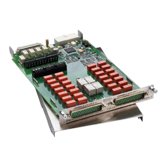
The 3740 card is shown in the following figure.
Item shipped may vary from model pictured here.
077184100 October 2024
Screw-terminal accessory
Figure 1: Model 3740 32-channel isolated switch card
*P077184100*
Model 3740 Isolated Switch Card
(on page 7). For more information regarding available cards
Instructions
1
Advertisement

Subscribe to Our Youtube Channel
Related Manuals for Tektronix KEITHLEY 3740


Summary of Contents for Tektronix KEITHLEY 3740
- Page 1 Model 3740 Isolated Switch Card Keithley Instruments Instructions 28775 Aurora Road Cleveland, Ohio 44139 1-800-833-9200 tek.com/keithley Introduction The 3740 offers 28 general-purpose form C channels that are ideal for routing power or other control devices. For higher power applications of up to 7 A, four additional high-current form A channels are provided. If any general-purpose signal requires routing to the Series 3700A mainframe backplane, there are terminal blocks on the card that are enabled with jumpers.
- Page 2 Model 3740 Isolated Switch Card Instructions This document describes how to install the plug-in card and make connections to it. For information on scanning, and on reading, writing, and controlling channels, refer to the Series 3700A System Switch/Multimeter Reference Manual, available at tek.com/keithley. Safety precautions for connections Shock hazard.
- Page 3 Model 3740 Isolated Switch Card Instructions To install a switching card into the instrument mainframe: 1. Turn the instrument off. 2. Position the instrument so that you are facing the rear panel. 3. Disconnect the power line cord and any other cables connected to the rear panel. 4.
- Page 4 Model 3740 Isolated Switch Card Instructions Verify card installation To verify that the card was properly installed: 1. If the 3700A is controlled remotely (REM is displayed), press EXIT to switch control to local. 2. On the 3700A front panel, press SLOT. The name and firmware version of the instrument is displayed. 3.
- Page 5 Model 3740 Isolated Switch Card Instructions Schematic The following figure shows a switching schematic for the 3740. In this figure, n represents the slot number. Channels 1 to 28 are 3 A. Channels 29 to 32 are 7 A. Figure 4: Model 3740 schematic 077184100 October 2024...
- Page 6 Model 3740 Isolated Switch Card Instructions Pseudocards You can perform open, close, and scan operations and configure your system without having a switch card installed in your instrument. If you are connected to a remote interface, you can assign a pseudocard to an empty switch card slot.
- Page 7 Model 3740 Isolated Switch Card Instructions Screw-terminal accessory The 3740-ST connectors are shown in the following figure. This screw-terminal accessory includes chassis ground connections for connecting cable shields. Figure 5: 3740-ST connections: Left side 077184100 October 2024...
- Page 8 Model 3740 Isolated Switch Card Instructions Figure 6: 3740-ST connections: Right side Wire the screw-terminal accessory These instructions describe how to connect wiring to a Series 3700A screw-terminal accessory. It is not necessary to remove a circuit board from its enclosure to wire the screw-terminal accessory.
- Page 9 Model 3740 Isolated Switch Card Instructions To wire the screw-terminal accessory: 1. Loosen the slotted captive screws (1) on the top cover. 2. Slide the top cover (2) away from the retaining tab (3), as shown in the following figure. Figure 7: Remove the top cover of the screw-terminal accessory 3.
- Page 10 Model 3740 Isolated Switch Card Instructions 4. As shown in the following figure, route your wiring through the slots at the rear of the screw-terminal accessory and connect it to the wiring terminals as described in Connection information (on page 4). Figure 8: Routing and securing cables with ties 5.
- Page 11 Model 3740 Isolated Switch Card Instructions 7. Slide the cover forward (1) and beneath the retaining tab (2), as shown in the following figure. 8. Fasten the two slotted captive screws (3). Figure 9: Install the screw-terminal assembly top cover Install the screw-terminal accessory Before using a screw-terminal assembly with an installed plug-in card, verify that the card is properly installed in the 3700A instrument and that the mounting screws are tightly fastened.
- Page 12 Model 3740 Isolated Switch Card Instructions 2. Make sure that the mounting screws (1 in the following figure) on the installed plug-in card are secure. Figure 10: Check 3700A card mounting screws 3. Align the screw-terminal assembly D-sub connectors with the connectors on the installed plug-in card, as shown in the following figure.
- Page 13 Model 3740 Isolated Switch Card Instructions Remove the screw-terminal accessory To remove a screw-terminal accessory from an installed plug-in card: 1. Remove all power from the 3700A instrument. 2. Turn the knob on the screw-terminal accessory counter-clockwise until it is completely disengaged. You may need to use a slotted screwdriver to loosen the knob.
- Page 14 Model 3740 Isolated Switch Card Instructions Pin number identification Pin numbers for the Model 3721-MTC-3 D-sub cables are shown in the following figure and table. Connect the drain wire to the shield at both ends of the 3721-MTC-3 cable. Figure 13: Model 3721-MTC-3 connectors Model 3721-MTC-3 pin number identification CONN 1 Color...
- Page 15 Model 3740 Isolated Switch Card Instructions Hardware interlocks This plug-in card can switch high-voltage signals. To prevent exposure to hazardous voltages, the plug-in card includes a hardware interlock. The hardware interlocks are present on the plug-in card and are designed to keep the plug-in card disconnected from the 3700A backplane.
- Page 16 Model 3740 Isolated Switch Card Instructions The supplied 5 V power source is not designed for use with external circuits. Only use this power source to energize the interlock relay. For reliable operation, be sure to provide a low-resistance path between the interlock pins. Significant resistance can cause the interlock circuit to fail to engage.
- Page 17 Model 3740 Isolated Switch Card Instructions Model Quiescent power Channel relay power (P Backplane relay power ) (milliwatts) consumption each ) consumption each (milliwatts) (milliwatts) 3720 Not applicable 3721 1350 Not applicable 3722 Not applicable 3723 100 (2-pole) 50 (1-pole) 3724 1150 3730...
- Page 18 Model 3740 Isolated Switch Card Instructions This produces the power consumption shown in the following table. × P × P Slot 1 power consumed = 1000 2 × 200 4 × 100 1800 Slot 2 power consumed = 1000 2 × 200 4 ×...
- Page 19 Model 3740 Isolated Switch Card Instructions Model 3740 connection log Use this table to record your 3740 connection information. Channel Color Description CH10 077184100 October 2024...
- Page 20 Model 3740 Isolated Switch Card Instructions Channel Color Description CH11 CH12 CH13 CH14 CH15 CH16 CH17 CH18 CH19 CH20 077184100 October 2024...
- Page 21 Model 3740 Isolated Switch Card Instructions Channel Color Description CH21 CH22 CH23 CH24 CH25 CH26 CH27 CH28 CH29 CH30 CH31 CH32 077184100 October 2024...
- Page 22 Safety precautions The following safety precautions should be observed before using this product and any associated instrumentation. Although some instruments and accessories would normally be used with nonhazardous voltages, there are situations where hazardous conditions may be present. This product is intended for use by personnel who recognize shock hazards and are familiar with the safety precautions required to avoid possible injury.
- Page 23 For safety, instruments and accessories must be used in accordance with the operating instructions. If the instruments or accessories are used in a manner not specified in the operating instructions, the protection provided by the equipment may be impaired. Do not exceed the maximum signal levels of the instruments and accessories. Maximum signal levels are defined in the specifications and operating information and shown on the instrument panels, test fixture panels, and switching cards.
Need help?
Do you have a question about the KEITHLEY 3740 and is the answer not in the manual?
Questions and answers