
Related Manuals for Tektronix KEITHLEY 2750


Summary of Contents for Tektronix KEITHLEY 2750
- Page 1 tek.com/keithley Model 2750 Multimeter/Switch System User’s Manual 2750-900-01 Rev. G June 2023 *P2750-900-01G* 2750-900-01G...
- Page 2 Model 2750 Multimeter/Switch System User's Manual...
- Page 3 © 2023, Keithley Instruments, LLC Cleveland, Ohio, U.S.A. All rights reserved. Any unauthorized reproduction, photocopy, or use of the information herein, in whole or in part, without the prior written approval of Keithley Instruments, LLC, is strictly prohibited. These are the original instructions in English. All Keithley Instruments product names are trademarks or registered trademarks of Keithley Instruments, LLC.
- Page 4 Safety precautions The following safety precautions should be observed before using this product and any associated instrumentation. Although some instruments and accessories would normally be used with nonhazardous voltages, there are situations where hazardous conditions may be present. This product is intended for use by personnel who recognize shock hazards and are familiar with the safety precautions required to avoid possible injury.
- Page 5 For safety, instruments and accessories must be used in accordance with the operating instructions. If the instruments or accessories are used in a manner not specified in the operating instructions, the protection provided by the equipment may be impaired. Do not exceed the maximum signal levels of the instruments and accessories. Maximum signal levels are defined in the specifications and operating information and shown on the instrument panels, test fixture panels, and switching cards.
-
Page 6: Table Of Contents
Table of contents Introduction ....................... 1-1 Welcome ..........................1-1 Extended warranty ....................... 1-1 Contact information ......................1-1 Customer documentation ..................... 1-2 Product software and drivers ....................1-2 What you should have received ................... 1-3 About this manual ........................ 1-3 General ratings ........................1-4 Installation ......................... - Page 7 Table of contents Model 2750 Multimeter/Switch System User's Manual Operation ........................4-1 Introduction .......................... 4-1 Basic DMM measurements using front-panel inputs ..............4-2 Closing and opening channels using system channel operation ..........4-3 Simple scanning ........................4-5 Basic DMM operation ......................4-7 DMM measurement capabilities ....................
-
Page 8: Introduction
If you have any questions after you review the information in this documentation, please contact your local Keithley Instruments office, sales partner, or distributor. You can also call the Tektronix corporate headquarters (toll-free inside the U.S. and Canada only) at 1-800-833-9200. For worldwide contact numbers, visit tek.com/contact-tek. -
Page 9: Customer Documentation
Section 1: Introduction Model 2750 Multimeter/Switch System User's Manual Customer documentation The documentation for the 2750 includes a User's Manual and Reference Manual. You can access them from tek.com/keithley. • User's Manual: Includes installation, instrument description, operation, and maintenance information. •... -
Page 10: What You Should Have Received
Model 2750 Multimeter/Switch System User's Manual Section 1: Introduction What you should have received Model 2750 was carefully inspected electrically and mechanically before shipment. After unpacking all items from the shipping carton, check for any obvious signs of physical damage that may have occurred during transit. There may be a protective film over the display lens, which you can remove. -
Page 11: General Ratings
Section 1: Introduction Model 2750 Multimeter/Switch System User's Manual General ratings Category Specification Power supply 100 V / 120 V / 220 V / 240 V Line frequency 50 Hz to 60 Hz and 400 Hz, automatically sensed at power-up Input and output connections Front panel (on page 3-1) and... -
Page 12: Installation
Section 2 Installation In this section: Introduction ................2-1 Switching module installation and connections ......2-1 Turning the instrument on and off ..........2-3 Power-up sequence..............2-4 Warmup period ................. 2-5 Identifying installed switching modules ........2-5 Keyclick ..................2-5 Display .................. -
Page 13: Module Installation
Section 2: Installation Model 2750 Multimeter/Switch System User's Manual Module installation Slot covers must be installed on unused slots to prevent personal contact with high-voltage circuits. Failure to recognize and observe standard safety precautions could result in personal injury or death due to electric shock. To install a switching module into the Model 2750: 1. -
Page 14: Turning The Instrument On And Off
Model 2750 Multimeter/Switch System User's Manual Section 2: Installation Turning the instrument on and off The 2750 operates from a line voltage of 100 V to 240 V at a frequency of 50 Hz or 60 Hz. Make sure the operating voltage in your area is compatible. The 2750 operates at line frequencies from 45 Hz to 66 Hz, and 360 Hz to 440 Hz. -
Page 15: Power-Up Sequence
Section 2: Installation Model 2750 Multimeter/Switch System User's Manual 2. Make sure that the front-panel POWER switch is in the off (O) position. 3. Connect the socket end of the supplied power cord to the AC receptacle on the rear panel. 4. -
Page 16: Warmup Period
Model 2750 Multimeter/Switch System User's Manual Section 2: Installation The serial number of the Model 2750 can be displayed by selecting the SNUM item of the SETUP menu. Press SHIFT and then SETUP to access the menu. Warmup period After the Model 2750 is turned on, it must be allowed to warm up for at least two hours to allow the internal temperature to stabilize. -
Page 17: Display
Section 2: Installation Model 2750 Multimeter/Switch System User's Manual Display Readings are displayed in engineering units, such as 100.23 mV, while annunciators indicate various states of operation. Refer to Display annunciators (on page 3-4) for a complete listing of display annunciators. The display test allows you to test display digit segments, annunciators, and the red slot indicator LEDs. -
Page 18: Saving A User Setup
Model 2750 Multimeter/Switch System User's Manual Section 2: Installation For remote programming, the SYSTem:PRESet and *RST commands reset the instrument. The *RST command returns the instrument to the *RST defaults. In most situations, the SYSTem:PRESet command returns the instrument to the factory default conditions. The exceptions are: •... -
Page 19: Restoring A Setup
Section 2: Installation Model 2750 Multimeter/Switch System User's Manual Restoring a setup To restore a setup: 1. Press SHIFT and then SETUP to access the restore setup menu. 2. Press ► to place the cursor on the present RESTORE setup (FACT, *RST, SAV0, SAV1, or SAV2). - Page 20 Model 2750 Multimeter/Switch System User's Manual Section 2: Installation Setting Factory *RST Set Diff Range Auto Auto Rate (DC) Slow (5 PLC) Slow (5 PLC) Dry circuit ohms Frequency and Period Digits 6½ digits 6½ digits Range 10 V 10 V Rate (aperture) 1 second 1 second...
- Page 21 Section 2: Installation Model 2750 Multimeter/Switch System User's Manual Setting Factory *RST Set Diff Scanning Disabled Disabled Autoscan No (off) No effect Type (Simple or Advanced) No effect No effect Simple scan Minimum channel 101, 201, 301, 401, or 501 101, 201, 301, 401, or 501 Maximum channel No effect...
-
Page 22: Instrument Description
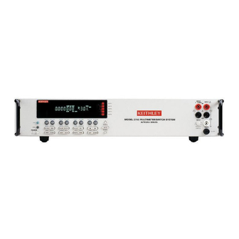
Section 3 Instrument description In this section: Front panel ................3-1 Rear panel................3-5 Front panel The front panel of the 2750 is shown in the following figure. Figure 2: 2750 front panel Most keys provide a dual function or operation. The nomenclature on a key indicates its unshifted function/operation, which is selected by pressing the key. -
Page 23: Function And Operation Keys
Section 3: Instrument description Model 2750 Multimeter/Switch System User's Manual 2 Function and operation keys Top row Unshifted Selects DC voltage measurement function. Selects AC voltage measurement function. Selects DC current measurement function. Selects AC current measurement function. Ω2 Selects 2-wire resistance measurement function. Ω4 Selects 4-wire resistance measurement function. -
Page 24: Range Keys
Model 2750 Multimeter/Switch System User's Manual Section 3: Instrument description Shifted Sets user delay between trigger and measurement. DELAY Selects dry circuit ohms (Ω4 must first be selected). DRYCKT Sets upper and lower limits for readings. LIMIT Enables or disables limits. ON/OFF Configures and enables filter for selected function. -
Page 25: Display Annunciators
Section 3: Instrument description Model 2750 Multimeter/Switch System User's Manual 4 Display annunciators Readings are being stored in the buffer. Indicates additional selections are available. <-> Beeper on for continuity or limits testing. Digital input/output or analog output active (set to non-default value). 4-wire resistance or 4-wire RTD temperature reading displayed. -
Page 26: Slot Indicators
Model 2750 Multimeter/Switch System User's Manual Section 3: Instrument description 5 Slot indicators Lighted lamp indicates that the slot has a switching module or pseudocard installed. When the VIEW option of the CARD menu is used, only the lamp that corresponds to the selected slot is lighted. - Page 27 Section 3: Instrument description Model 2750 Multimeter/Switch System User's Manual Figure 3: 2750 rear panel 1 DIGITAL I/O Male DB-9 connector for digital input (trigger link in) and digital outputs. 2 TRIG LINK Eight-pin micro-DIN connector for sending and receiving trigger pulses among connected instruments.
-
Page 28: Operation
Section 4 Operation In this section: Introduction ................4-1 Basic DMM operation ............... 4-7 Range ..................4-40 Relative offset ................ 4-41 Rate ..................4-42 Introduction Before operating an instrument with a switching module, verify that the switching module is properly installed and the mounting screws are tightly fastened. If the mounting screws are not properly connected, an electrical shock hazard may be present. -
Page 29: Basic Dmm Measurements Using Front-Panel Inputs
Section 4: Operation Model 2750 Multimeter/Switch System User's Manual Basic DMM measurements using front-panel inputs When shipped from the factory, the 2750 is set to continuously measure DC volts. Some default settings for the DCV function include autorange enabled, 6½-digit resolution, filter enabled, and slow reading rate. -
Page 30: Closing And Opening Channels Using System Channel Operation
Model 2750 Multimeter/Switch System User's Manual Section 4: Operation Closing and opening channels using system channel operation The following discussion assumes a multiplexing switching module, such as a 7700, installed in slot 1 of the mainframe. Switching module installation is described in Switching module installation and connections (on page 2-1). - Page 31 Section 4: Operation Model 2750 Multimeter/Switch System User's Manual The figures in this topic show simplified schematics of the switching module. They show that a single switch is closed to connect an input channel to the DMM. Multiple switching is used to make proper connections to the DMM.
-
Page 32: Simple Scanning
Model 2750 Multimeter/Switch System User's Manual Section 4: Operation Exercise 2: Closing and opening channels (system channel operation) The following exercise demonstrates a sequence to close and open channels of a Model 7700 installed in slot 1 of the mainframe. It is a good safe practice to start and end a switching sequence by opening all channels. - Page 33 Section 4: Operation Model 2750 Multimeter/Switch System User's Manual Reading count (RDG CT): For both STEP and SCAN, the reading count specifies the number of readings to store in the buffer. For STEP, the reading count determines the number of channels to scan. For SCAN, the reading count also determines the number of scans to perform.
-
Page 34: Basic Dmm Operation
Model 2750 Multimeter/Switch System User's Manual Section 4: Operation Exercise 3: Simple scanning The scanning example in the following steps assumes a Model 7700 installed in slot 1 of the mainframe. The scan uses the factory default settings (DCV) to scan eight channels and store the readings in the buffer. -
Page 35: Dmm Measurement Capabilities
Section 4: Operation Model 2750 Multimeter/Switch System User's Manual DMM measurement capabilities The DMM of the Model 2750 can make the following measurements: • DCV: DC voltage measurements from 0.1 µV to 1000 V. • ACV: AC voltage measurements from 0.1µ V to 750 V. •... -
Page 36: High Energy Circuit Safety Precautions
Model 2750 Multimeter/Switch System User's Manual Section 4: Operation High energy circuit safety precautions To optimize safety when measuring voltage in high energy distribution circuits, read and use the directions in this topic. Dangerous arcs of an explosive nature in a high energy circuit can cause severe personal injury or death. -
Page 37: Voltage Measurements (Dcv And Acv)
Section 4: Operation Model 2750 Multimeter/Switch System User's Manual To test power circuits: 1. De-energize the circuit using the regular installed connect-disconnect device. For example, remove the power cord from the device or turn off the power switch. 2. Attach the test leads to the circuit under test. Use appropriate safety rated test leads for this application. - Page 38 Model 2750 Multimeter/Switch System User's Manual Section 4: Operation Front-panel inputs When using the front-panel input terminals, connect the test leads to the INPUT HI and LO terminals as shown in the following figure. Figure 8: DCV and ACV connections using front-panel inputs Model 7700 connections for voltage measurements Connections for the Model 7700 switching module are shown in the following figure.
- Page 39 Section 4: Operation Model 2750 Multimeter/Switch System User's Manual You can use ratio and channel average calculations on voltage measurements. Ratio calculates the reading ratio of two channels, while channel average calculates the reading average of two channels. For these calculations, paired switching channels are used. Primary channels 1 through 10 are paired to channels 11 through 20 (channel 1 paired to channel 11, channel 2 paired to channel 12, and so on), as shown in C in the figure.
- Page 40 Model 2750 Multimeter/Switch System User's Manual Section 4: Operation Volts measurement procedure Do not apply more than maximum input levels indicated in Front-panel input (on page 4-11) Model 7700 switching module (on page 4-11) or instrument damage may occur. The voltage limit is subject to the 8 ×...
-
Page 41: Current Measurements (Dci And Aci)
Section 4: Operation Model 2750 Multimeter/Switch System User's Manual Current measurements (DCI and ACI) The Model 2750 can make DCI measurements from 10 nA to 3 A and ACI measurements from 1 µA to 3 A Front-panel input connections When using the front-panel input terminals, connect the test leads to the AMPS and INPUT LO terminals as shown in the following figure. - Page 42 Model 2750 Multimeter/Switch System User's Manual Section 4: Operation Current measurement procedure Do not apply more than 3 A to the input. Applying excessive current to the input will cause the AMPS fuse to blow. If you are using the Model 7700 switching module, the maximum allowable voltage is 60 VDC or 30 V .
-
Page 43: Resistance Measurements (Ω2 And Ω4)
Section 4: Operation Model 2750 Multimeter/Switch System User's Manual Resistance measurements (Ω2 and Ω4) The Model 2750 uses the constant-current method to measure resistance from 1 Ω to 1 MΩ. The Model 2750 sources a constant current (I) to the resistance and measures the voltage (V). - Page 44 Model 2750 Multimeter/Switch System User's Manual Section 4: Operation Front-panel inputs Connections for resistance measurements are shown in the following figure. For 2-wire resistance measurements (Ω2), connect the test leads to INPUT HI and LO as shown in A, Ω2 Connections. For 4-wire resistance (Ω4), connect the test leads to INPUT HI and LO, and SENSE Ω4 HI and LO as shown in B, Ω4 Connections.
- Page 45 Section 4: Operation Model 2750 Multimeter/Switch System User's Manual Model 7700 connections for resistance measurements Connections for the Model 7700 switching module are shown in the following figure. As shown in A, Ω2 Connections, each of the 20 channels can be used to perform Ω2 measurements.
- Page 46 Model 2750 Multimeter/Switch System User's Manual Section 4: Operation Standard resistance measurements For front-panel inputs, do not apply more than 1000 V between INPUT HI and LO, or PEAK instrument damage may occur. For Model 7700 switching modules, do not apply more than 300 VDC or V between input high (H) or input low (L), or switching module damage may occur.
- Page 47 Section 4: Operation Model 2750 Multimeter/Switch System User's Manual Offset-compensated ohms The presence of thermal EMFs (V ) can adversely affect low-resistance measurement accuracy. To overcome these unwanted offset voltages, you can use offset-compensated ohms (OCOMP). Offset-compensated ohms measurements can be performed on the 1 Ω, 10 Ω, 100 Ω, 1 kΩ, and 10 kΩ...
- Page 48 Model 2750 Multimeter/Switch System User's Manual Section 4: Operation Performing offset-compensated ohms measurements Offset-compensated ohms can only be performed on the Ω4 function using the 1 Ω, 10 Ω, 100 Ω, 1 kΩ, or 10 kΩ range. Make sure you use 4-wire connections to the DUT, as shown Connections (on page 4-10).
- Page 49 Section 4: Operation Model 2750 Multimeter/Switch System User's Manual 6. If using a switching module, press the CLOSE key to close the channel. Use ◄, ►, ▲, and ▼ to key in the channel number and press ENTER. The previously closed channels (if any) open, and the specified channel or channel pair closes.
- Page 50 Model 2750 Multimeter/Switch System User's Manual Section 4: Operation Oxide films may also build up in connections on a semiconductor wafer. To accurately measure the resistance introduced by the oxide film, dry circuit ohms should be used to prevent oxide film puncture. You should also use the dry circuit ohms feature to measure devices that could be damaged by high open-circuit voltage.
- Page 51 Section 4: Operation Model 2750 Multimeter/Switch System User's Manual 6. Connect the resistances to be measured. 7. If using a switching module, press the CLOSE key to close the channel. Use ◄, ►, ▲, and ▼ to key in the channel number and press ENTER. The previously closed channels (if any) open, and the specified channel or channel pair closes.
-
Page 52: Temperature Measurements
Model 2750 Multimeter/Switch System User's Manual Section 4: Operation Temperature measurements The Model 2750 can measure temperature using thermocouples, thermistors, and 4-wire RTDs. Thermocouples For thermocouples, temperature measurement range depends on which type of thermocouple is being used. Thermocouples that are supported include types J, K, N, T, E, R, S, and B. - Page 53 Section 4: Operation Model 2750 Multimeter/Switch System User's Manual Reference junctions A reference junction is the cold junction in a thermocouple circuit which is held at a stable, known temperature. It is at the cold junction where dissimilar wire connections must be made.
- Page 54 Model 2750 Multimeter/Switch System User's Manual Section 4: Operation Figure 15: Simulated reference junction using the Model 7700 The copper wire to thermocouple wire connections are immersed (but electrically isolated) in the ice bath, and the user enters the 0 °C simulated reference temperature into the Model 2750.
- Page 55 Section 4: Operation Model 2750 Multimeter/Switch System User's Manual Open thermocouple detection Long lengths of thermocouple wire can have a large amount of capacitance that is seen at the input of the DMM. If an intermittent open occurs in the thermocouple circuit, the capacitance could cause an erroneous on-scale reading.
- Page 56 Model 2750 Multimeter/Switch System User's Manual Section 4: Operation 4-wire RTDs For 4-wire RTDs, the temperature measurement range is −200 °C to 630 °C (0.01 °C resolution). RTD types that are supported include D100, F100, PT385, and PT3916. A USER type is available to modify RTD parameters, such as the resistance at 0 °C. The USER type can be enabled from the front panel, but the settings can only be changed using remote programming.
- Page 57 Section 4: Operation Model 2750 Multimeter/Switch System User's Manual Thermocouple connections Thermocouples are color coded to identify the positive (+) and negative (−) leads, as shown in the following table. Note that the negative (−) lead for U.S. type thermocouples is red. Color codes of thermocouple wires Thermocouple Thermocouple...
- Page 58 Model 2750 Multimeter/Switch System User's Manual Section 4: Operation You can also connect the thermocouple wires directly to the screw terminals (internal reference junction) as shown in the following figure. Using a simulated reference junction may be inconvenient but it provides more accurate temperature measurements (assuming the user enters a precise reference temperature).
- Page 59 Section 4: Operation Model 2750 Multimeter/Switch System User's Manual 4-wire RTD connections The following figure shows 4-wire RTD connections to the 2750. For the Model 7700 switching module, paired channels are used to perform the 4-wire measurement. The two input leads of the RTD are connected to a primary channel (1 through 10), while the two sense leads are connected to its paired channel (11 through 20).
- Page 60 Model 2750 Multimeter/Switch System User's Manual Section 4: Operation Thermocouple temperature measurement configuration The steps to configure thermocouple measurements are provided in the following table. After pressing SHIFT and then SENSOR, the menu starts at step 1 to select measurement units. Each time you press ENTER to make a selection, the menu will automatically go to the next selection.
- Page 61 Section 4: Operation Model 2750 Multimeter/Switch System User's Manual Thermistor temperature measurement configuration Step Menu structure Description UNITS: C, F, or K Select temperature measurement units (°C, °F, or K). SENS: THRMSTR Select the thermistor transducer. TYPE: 2200 Ω, 5000 Ω, or 10 kΩ Select thermistor resistance.
- Page 62 Model 2750 Multimeter/Switch System User's Manual Section 4: Operation Temperature measurement procedure Make sure the INPUTS switch is in the correct position. To use front-panel inputs, it must be in the F (out) position. For switching modules, it must be in the R (in) position. To measure temperature: 1.
-
Page 63: Frequency And Period Measurements
Section 4: Operation Model 2750 Multimeter/Switch System User's Manual Frequency and period measurements The Model 2750 can make frequency measurements from 3 Hz to 500 kHz on voltage ranges of 100 mV, 1 V, 10 V, 100 V, and 750 V. Period (1 / frequency) measurements can be taken from 2 µs to 333 ms on the same voltage ranges as the frequency. - Page 64 Model 2750 Multimeter/Switch System User's Manual Section 4: Operation Frequency and period connections Front-panel inputs When using the front-panel input terminals, connect the test leads to the INPUT HI and LO terminals as shown in the following figure. Figure 20: FREQ and PERIOD connections for front-panel inputs Model 7700 connections for frequency and period measurements Connections for the Model 7700 switching module are shown in the following figure.
- Page 65 Section 4: Operation Model 2750 Multimeter/Switch System User's Manual Frequency and period measurement procedure Make sure the INPUTS switch is in the correct position. To use front-panel inputs, it must be in the F (out) position. For switching modules, it must be in the R (in) position. Do not apply more than maximum input levels indicated in the figures in Frequency and period connections...
-
Page 66: Continuity Testing
Model 2750 Multimeter/Switch System User's Manual Section 4: Operation Continuity testing The 2750 can test continuity using the 2-wire 1 kΩ range. After selecting continuity, you are prompted to enter the threshold resistance level (1 Ω to 1000 Ω). When the measured circuit is below the set threshold level, the instrument beeps and displays the resistance readings. -
Page 67: Range
Section 4: Operation Model 2750 Multimeter/Switch System User's Manual Continuity testing procedure Make sure the INPUTS switch is in the correct position. To use front-panel inputs, it must be in the F (out) position. For switching modules, it must be in the R (in) position. The beeper can be disabled using the SYSTem:BEEPer:STATe OFF command. -
Page 68: Measurement Ranges And Maximum Readings
Model 2750 Multimeter/Switch System User's Manual Section 4: Operation Measurement ranges and maximum readings The measurement range affects the accuracy of the measurement and the maximum signal that can be measured. The measurement ranges for each function, except frequency, period, and temperature, are listed in the following table. Function Ranges Maximum reading... -
Page 69: Rate
Section 4: Operation Model 2750 Multimeter/Switch System User's Manual When a relative offset value is established for a measure function, the value is the same for all ranges for that measure function. For example, if 50 V is set as the relative offset value on the 100 V range, the relative offset value is also 50 V on the 1000 V, 10 V, 1 V, and 100 mV ranges. - Page 70 Model 2750 Multimeter/Switch System User's Manual Section 4: Operation Figure 24: Speed versus noise characteristics The front-panel RATE settings for all but the AC functions are explained as follows: • FAST sets integration time to 0.1 PLC. Use FAST if speed is of primary importance (at the expense of increased reading noise and fewer usable digits).
- Page 71 Section 4: Operation Model 2750 Multimeter/Switch System User's Manual From the front panel, setting the rate for one function affects all the other functions. For example, if you set DCV for medium speed, the other functions are also set to medium speed.
-
Page 72: Switch Module Channel Operation
Section 5 Switch module channel operation In this section: Closing and opening switching module channels ..... 5-1 Close/open overview ..............5-1 Channel assignments ............... 5-3 System channel operation ............5-3 Identifying installed modules ............ 5-9 Closing and opening switching module channels This section includes descriptions of the following: •... - Page 73 Section 5: Switch module channel operation Model 2750 Multimeter/Switch System User's Manual There are two modes of close and open operations: • System channel operation: This is the mode of operation that should be used by most users. When you close an input channel or channel-pair, other channels on the switching module close automatically to internally connect it the DMM of the Model 2750.
-
Page 74: Channel Assignments
Model 2750 Multimeter/Switch System User's Manual Section 5: Switch module channel operation Channel assignments The Model 2750 has five slots for switching modules. To control the appropriate switching module, the slot number must be included with the switching module channel number when you specify a channel. -
Page 75: 2-Wire Functions
Section 5: Switch module channel operation Model 2750 Multimeter/Switch System User's Manual • The system channel close keys can only close measurement channels that will automatically connect to the DMM. Non-measurement channels cannot be closed by the system channel close keys. Use the VIEW option of the CARD menu to display all closed channels in the mainframe. -
Page 76: 4-Wire Functions (Paired Channels)
Model 2750 Multimeter/Switch System User's Manual Section 5: Switch module channel operation 4-wire functions (paired channels) A 4-wire function, such as Ω4, requires that another measurement channel be paired to the system channel. For example, if the switching module has 20 measurement channels, channels 1 through 10 can be used as the system channel, while channels 11 through 20 are used as the paired channel. -
Page 77: Controlling The System Channel
Section 5: Switch module channel operation Model 2750 Multimeter/Switch System User's Manual Controlling the system channel When a measurement channel is closed, a previous system channel (and, for a 4-wire function, its paired channel) is first opened. The closed measurement channel becomes the system channel. - Page 78 Model 2750 Multimeter/Switch System User's Manual Section 5: Switch module channel operation CLOSE key (SINGLE menu option) The SINGLE menu option for the CLOSE key can be used to select a measurement channel as the system channel, as shown in the following figure. Figure 28: System channel operation: Specifying the measurement channel to close To select the system channel: 1.
- Page 79 Section 5: Switch module channel operation Model 2750 Multimeter/Switch System User's Manual INVALID CHAN indicates that the channel is not a valid measurement channel. The following actions cause this error: • Trying to close a non-measurement channel, such as a backplane isolation channel, a channel that sets the pole mode, or a channel that cannot be internally connected to the DMM.
-
Page 80: Non-Amp And Non-Measure Switching Modules
Model 2750 Multimeter/Switch System User's Manual Section 5: Switch module channel operation Non-amp and non-measure switching modules There are Keithley switching modules that do not support current measurements and there are modules that do not support any measurements. For switching modules that do not support current measurements, when an amps function is selected (DCI or ACI), you cannot use system channel operation to close channels on that module. -
Page 81: Card Menu
Section 5: Switch module channel operation Model 2750 Multimeter/Switch System User's Manual CARD menu The CARD menu identifies the switching modules installed in the mainframe. You can use this menu for the following operations: • Configure digital inputs and outputs, and analog outputs for switching modules that have one or more of those capabilities, such as the Models 7706 and 7707. - Page 82 Model 2750 Multimeter/Switch System User's Manual Section 5: Switch module channel operation The items and options of the menu are defined in the following list. CARD: CONFIG: This menu item is used to configure switching modules. The channels of the Model 7700 switching module and other similar type modules do not need to be configured.
-
Page 83: Maintenance
Section 6 Maintenance In this section: Introduction ................6-1 Finding the serial number of the instrument ......6-1 AMPS fuse replacement (front-panel AMPS input) ....6-2 Setting line voltage and replacing fuse ........6-3 Introduction This section describes routine maintenance of the instrument that an operator can perform. Finding the serial number of the instrument The instrument serial number is on a label on the rear panel of the instrument. -
Page 84: Amps Fuse Replacement (Front-Panel Amps Input)
Section 6: Maintenance Model 2750 Multimeter/Switch System User's Manual AMPS fuse replacement (front-panel AMPS input) Make sure the instrument is disconnected from the power line and other equipment before checking or replacing the AMPS fuse. Failure to disconnect all power may expose you to hazardous voltages, that, if contacted, could cause personal injury or death. -
Page 85: Setting Line Voltage And Replacing Fuse
Model 2750 Multimeter/Switch System User's Manual Section 6: Maintenance Setting line voltage and replacing fuse A fuse on the 2750 rear panel protects the power-line input of the instrument. The following instructions describe how to replace the fuse. You do not need to return your instrument for service if the fuse is damaged. - Page 86 Section 6: Maintenance Model 2750 Multimeter/Switch System User's Manual If a fuse continues to become damaged, a circuit malfunction exists and must be corrected. Return the instrument to Keithley Instruments for repair. Line fuse Line voltage Rating Manufacturer part number Keithley part number 100 V/120 V 0.630 A, 250 V, slow-blow...
-
Page 87: Status And Error Messages
Section 7 Status and error messages In this section: Status and error messages ............7-1 Status and error messages SCPI-confirmed messages are described in "Volume 2: Command Reference" of the Standard Commands for Programmable Instruments (SCPI)., available at https://www.ivifoundation.org/docs/scpi-99.pdf. Refer to the SYSTem:ERRor? command description in the Model 2750 Reference Manual. - Page 88 Section 7: Status and error messages Model 2750 Multimeter/Switch System User's Manual Number Description Event -211 Trigger ignored -210 Trigger error -202 Settings lost due to rtl -201 Invalid while in local -200 Execution error -178 Expression data not allowed -171 Invalid expression -170...
- Page 89 Model 2750 Multimeter/Switch System User's Manual Section 7: Status and error messages Number Description Event +305 High limit 2 event +306 Reading available +307 Buffer user-selectable event +308 Buffer available +309 Buffer half full +310 Buffer full +311 Buffer overflow +312 Buffer one quarter full +313...
- Page 90 Section 7: Status and error messages Model 2750 Multimeter/Switch System User's Manual Number Description Event +460 10 vac full scale error +461 10 vac noise error +462 100 vac zero error +463 100 vac full scale error +464 750 vac zero error +465 750 vac full scale error +466...
- Page 91 Model 2750 Multimeter/Switch System User's Manual Section 7: Status and error messages Number Description Event +524 Unsupported card detected +525 Scancard memory pattern mismatch +610 Questionable calibration +611 Questionable temperature +700 Invalid function in scanlist +800 RS-232 Framing error detected +802 RS-232 Overrun detected +803...
-
Page 92: Next Steps
Section 8 Next steps In this section: Additional 2750 information ............8-1 Additional 2750 information For additional information about the 2750, refer to tek.com/keithley, which contains the most up-to-date information. From the website, you can access: • The Model 2750 Reference Manual, which contains detailed instrument information, including descriptions of the SCPI commands. - Page 93 Specifications are subject to change without notice. All Keithley trademarks and trade names are the property of Keithley Instruments. All other trademarks and trade names are the property of their respective companies. Keithley Instruments • 28775 Aurora Road • Cleveland, Ohio 44139 • 1-800-833-9200 • tek.com/keithley 04/2022...
Need help?
Do you have a question about the KEITHLEY 2750 and is the answer not in the manual?
Questions and answers