Tektronix Keithley 3700A Series User Manual
System switch/multimeter
Hide thumbs
Also See for Keithley 3700A Series:
- Applications manual (52 pages) ,
- Quick start manual (18 pages)

Subscribe to Our Youtube Channel
Related Manuals for Tektronix Keithley 3700A Series


Summary of Contents for Tektronix Keithley 3700A Series
- Page 1 tek.com/keithley Series 3700A System Switch/Multimeter User’s Manual 3700AS-900-01 Rev. C March 2021 *P3700AS-900-01C* 3700AS-900-01C...
- Page 2 Series 3700A System Switch/Multimeter User's Manual...
- Page 3 © 2021, Keithley Instruments, LLC Cleveland, Ohio, U.S.A. All rights reserved. Any unauthorized reproduction, photocopy, or use of the information herein, in whole or in part, without the prior written approval of Keithley Instruments, LLC, is strictly prohibited. These are the original instructions in English. All Keithley Instruments product names are trademarks or registered trademarks of Keithley Instruments, LLC.
- Page 4 Safety precautions The following safety precautions should be observed before using this product and any associated instrumentation. Although some instruments and accessories would normally be used with nonhazardous voltages, there are situations where hazardous conditions may be present. This product is intended for use by personnel who recognize shock hazards and are familiar with the safety precautions required to avoid possible injury.
- Page 5 For safety, instruments and accessories must be used in accordance with the operating instructions. If the instruments or accessories are used in a manner not specified in the operating instructions, the protection provided by the equipment may be impaired. Do not exceed the maximum signal levels of the instruments and accessories. Maximum signal levels are defined in the specifications and operating information and shown on the instrument panels, test fixture panels, and switching cards.
-
Page 6: Table Of Contents
Table of contents Introduction ......................1-1 Welcome ..........................1-1 Introduction to this manual ....................1-1 Contact information ......................1-1 Extended warranty ....................... 1-2 Product documentation, drivers, and software ..............1-2 Measuring capabilities......................1-3 Safety precautions for connections ..................1-4 Using the front-panel interface ................2-1 Introduction .......................... - Page 7 Table of contents Series 3700A System Switch/Multimeter User's Manual Open and close channels from the card pages ................. 3-4 Set up channel patterns from the web interface ................ 3-6 Scan Builder page ........................ 3-8 Create a scan list ........................3-9 Run the scan ...........................
-
Page 8: Introduction
If you have any questions after you review the information in this documentation, please contact your local Keithley Instruments office, sales partner, or distributor. You can also call the Tektronix corporate headquarters (toll-free inside the U.S. and Canada only) at 1-800-833-9200. For worldwide... -
Page 9: Extended Warranty
Section 1: Introduction Series 3700A System Switch/Multimeter User's Manual Extended warranty Additional years of warranty coverage are available on many products. These valuable contracts protect you from unbudgeted service expenses and provide additional years of protection at a fraction of the price of a repair. Extended warranties are available on new and existing products. Contact your local Keithley Instruments office, sales partner, or distributor for details. -
Page 10: Measuring Capabilities
Series 3700A System Switch/Multimeter User's Manual Section 1: Introduction To identify IP addresses of instruments connected to the local area network (LAN) that support VXI-11 discovery protocol, including the Series 3700A, you can also use the LXI Discovery Tool, available from the Resources tab of the LXI Consortium website (lxistandard.org). -
Page 11: Safety Precautions For Connections
Section 1: Introduction Series 3700A System Switch/Multimeter User's Manual Safety precautions for connections Connection information for switching cards is intended for qualified service personnel. Do not attempt to connect DUT or external circuitry to a switching card unless qualified to do so. To prevent electric shock that could result in serious injury or death, comply with these safety precautions: Before making or breaking any connections to the switching card, make sure the Series... -
Page 12: Using The Front-Panel Interface
Section 2 Using the front-panel interface In this section: Introduction ................2-1 Series 3700A front panel overview ........... 2-2 Channel identification ............... 2-7 Operating a channel from the front panel ......... 2-8 Viewing the close or open status of a channel ....... 2-10 Emulate a Model 3706 ............ -
Page 13: Series 3700A Front Panel Overview
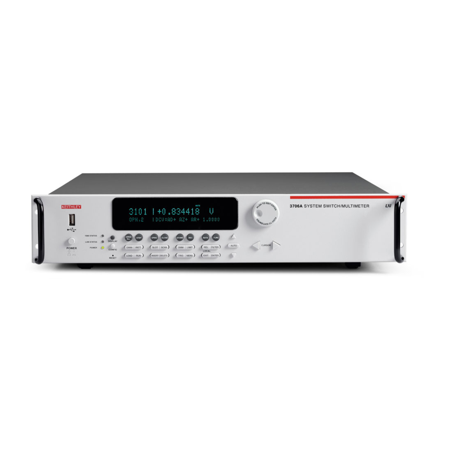
Section 2: Using the front-panel interface Series 3700A System Switch/Multimeter User's Manual Series 3700A front panel overview The Series 3700A includes several models that support different features. The following figures show the front panels of each of the models; a brief description of the features follows the figures. For more detailed information about the Model 3706A front panel, see the “General operation”... -
Page 14: The Usb Port
Series 3700A System Switch/Multimeter User's Manual Section 2: Using the front-panel interface (1) The USB port Use the front-panel USB port to connect a USB flash drive. The USB flash drive can be used to store reading buffer data, scripts, and user setup options. (USB port) (2) The display During setup, the display shows menu choices that you can use to configure the instrument. - Page 15 Section 2: Using the front-panel interface Series 3700A System Switch/Multimeter User's Manual The table below lists the display indicators and what they mean. Indicator Meaning AUTO Measure autorange is selected EDIT Instrument is in the editing mode Questionable reading or invalid calibration step FILT Digital filter is enabled LSTN...
-
Page 16: The Navigation Wheel
Series 3700A System Switch/Multimeter User's Manual Section 2: Using the front-panel interface (3) The navigation wheel Turn the navigation wheel to scroll to a menu option or to change the value of the selected numeric parameter. Pressing the navigation wheel has the same functionality as pressing the ENTER key. - Page 17 Section 2: Using the front-panel interface Series 3700A System Switch/Multimeter User's Manual Key descriptions Description Toggles between the channel measure display, closed channels list, and the user DISPLAY message mode Configures a function or operation CONFIG Restores factory default LAN settings RESET Opens all closed channels OPEN ALL...
-
Page 18: Channel Identification
Series 3700A System Switch/Multimeter User's Manual Section 2: Using the front-panel interface Channel identification The specifiers for the channels depend on the type of channels, as defined in the following topics. Matrix card channel specifiers The channels on the matrix cards are referred to by their slot, bank, row, and column numbers: •... -
Page 19: Multiplexer, Digital I/O, Totalizer, And Dac Channel Specifiers
Section 2: Using the front-panel interface Series 3700A System Switch/Multimeter User's Manual Multiplexer, digital I/O, totalizer, and DAC channel specifiers The channels for multiplexer (MUX), digital I/O, totalizer, and digital to analog converter channels are referred to by their slot and channel numbers: •... - Page 20 Series 3700A System Switch/Multimeter User's Manual Section 2: Using the front-panel interface 6. Set the channel number (or rows and columns for installed matrix cards), identified as 2 in the following figure, as needed using the navigation wheel 7. The display shows the current state of the selected channel in the bottom row, as shown by 3 in the following figure.
-
Page 21: Viewing The Close Or Open Status Of A Channel
Section 2: Using the front-panel interface Series 3700A System Switch/Multimeter User's Manual Viewing the close or open status of a channel Closed channels are shown separated by commas after the CLS: characters on the display of the instrument. If no channels are closed, <none> is displayed here. If the list of closed channels extends past one screen, ... -
Page 22: Channel Patterns
Series 3700A System Switch/Multimeter User's Manual Section 2: Using the front-panel interface Channel patterns You can use channel patterns as a convenient way to refer to a group of switching channels and backplane relays with a single alphanumeric name. When you perform close or open operations on a channel pattern, only the channels and analog backplane relays that are in the channel pattern are affected. -
Page 23: Performing Close And Open Operations On Channel Patterns
Section 2: Using the front-panel interface Series 3700A System Switch/Multimeter User's Manual Performing close and open operations on channel patterns Careless channel pattern operation could create an electric shock hazard that could result in severe injury or death. Improper operation can also cause damage to the switching cards and external circuitry. -
Page 24: Front-Panel Scanning
Series 3700A System Switch/Multimeter User's Manual Section 2: Using the front-panel interface To create a channel label using the front panel: 1. Press the CONFIG key, and then press the CHAN key. The CHANNEL ATTR MENU opens. 2. Select LABEL, and the press the navigation wheel 3. - Page 25 Section 2: Using the front-panel interface Series 3700A System Switch/Multimeter User's Manual In addition to the default DMM configurations, the scan list will also show the names of any user-created DMM configurations. For more information about user-created DMM configurations, see "Save DMM configurations"...
-
Page 26: Taking Measurements Without A Switch Card
Series 3700A System Switch/Multimeter User's Manual Section 2: Using the front-panel interface Taking measurements without a switch card Pseudocards You can perform most open, close, and scan operations and configure your system without having an actual plug-in card installed in your instrument. Using the remote interface, you can assign a pseudocard, allowing the instrument to operate as if a plug-in card were installed. -
Page 27: Using The Analog Backplane Connector To Make Measurements
Section 2: Using the front-panel interface Series 3700A System Switch/Multimeter User's Manual Using the analog backplane connector to make measurements You can perform measurements without an installed switch card by using the rear-panel analog backplane connection, which is always connected to the digital multimeter (DMM) input. To connect to the analog backplane as shown below, use a standard DB-15 mating connector (not supplied). -
Page 28: Using The Web Interface
Section 3 Using the web interface In this section: Introduction ................3-1 Connecting to the instrument web interface ......3-1 Web interface home page ............3-2 Log in to the instrument ............3-2 Card pages ................3-3 Scan Builder page ..............3-8 TSB Embedded .............. -
Page 29: Web Interface Home Page
Section 3: Using the web interface Series 3700A System Switch/Multimeter User's Manual To manually set up the IP address to connect to the instrument web interface: 1. Connect the Series 3700A to the LAN and confirm that the LAN Status light on the instrument is illuminated. -
Page 30: Card Pages
Series 3700A System Switch/Multimeter User's Manual Section 3: Using the web interface 3. Enter the password (the default is admin). Figure 12: Enter web interface password 4. Click Login. The default password is admin. If the password has been changed, it is available from the front panel of the instrument. -
Page 31: Open And Close Channels From The Card Pages
Section 3: Using the web interface Series 3700A System Switch/Multimeter User's Manual Open and close channels from the card pages You can open and close channels from the card pages in several ways. The simplest method is to click a connection. The channel changes state to open or closed. When the channel is open, the connection will look similar to one of the following graphics (the actual item on the web interface depends on the installed card): Figure 14: Web interface open channel... - Page 32 Series 3700A System Switch/Multimeter User's Manual Section 3: Using the web interface Exercise: Close multiple channels using the web interface This exercise describes how to close channels and channel patterns using the web interface. To close multiple channels using the web interface: 1.
-
Page 33: Set Up Channel Patterns From The Web Interface
Section 3: Using the web interface Series 3700A System Switch/Multimeter User's Manual 5. Click "11102" to close that channel and open all other channels. Figure 21: Series 3700A web interface exclusive close Set up channel patterns from the web interface You can use channel patterns as a convenient way to refer to a group of switching channels with a single alphanumeric name. - Page 34 Series 3700A System Switch/Multimeter User's Manual Section 3: Using the web interface Figure 22: Series 3700A channel pattern configuration dialog box Exercise: Close channels in "Test1Pattern" from the web interface To close channels in channel pattern "Test1Pattern" from the web interface: 1.
-
Page 35: Scan Builder Page
Section 3: Using the web interface Series 3700A System Switch/Multimeter User's Manual 4. Click Close to close the channels. 5. When you are done acting on this channel pattern, click Close at the bottom of the dialog box to exit. To delete a channel pattern from the web interface: 1. -
Page 36: Create A Scan List
Series 3700A System Switch/Multimeter User's Manual Section 3: Using the web interface Create a scan list Before you can run a scan, you must create a scan list. A scan list is a set of steps that runs in order during a scan. -
Page 37: Run The Scan
Section 3: Using the web interface Series 3700A System Switch/Multimeter User's Manual Run the scan You can run a scan in one of several ways: • Background: Runs the scan in the background so that you can perform other tasks while the scan is running. - Page 38 Series 3700A System Switch/Multimeter User's Manual Section 3: Using the web interface Selecting scan triggers You can choose the triggers that will be used to start the scan. The options to start the scan are: • Immediate: When Immediate is selected, the scan starts as soon as you click Execute Background on the Build &...
-
Page 39: Tsb Embedded
Section 3: Using the web interface Series 3700A System Switch/Multimeter User's Manual Selecting measurement triggers You can also select the trigger to use to take a measurement for each scan step. • Immediate: When immediate is selected, the measurement is taken as soon as the channel is closed. - Page 40 Series 3700A System Switch/Multimeter User's Manual Section 3: Using the web interface Figure 24: Web interface: Select TSB embedded 2. You must log in to the instrument to use TSB Embedded. After logging in, you can access the options on the TSB Embedded page. 3.
- Page 41 Section 3: Using the web interface Series 3700A System Switch/Multimeter User's Manual CardChannels = function(SlotNumber) if slot[SlotNumber].idn == "Empty Slot" then print(" Slot is Empty") else if (slot[SlotNumber].startchannel.voltage == nil) and (slot[SlotNumber].endchannel.voltage == nil) then print(" no voltage channels") else print("...
- Page 42 Series 3700A System Switch/Multimeter User's Manual Section 3: Using the web interface Commands and parameters for Series 3700A are case-sensitive. It is important to type in the commands exactly as shown to avoid any syntax or execution errors. 5. Click Save Script. The script is added to the User Scripts list. 6.
- Page 43 Section 3: Using the web interface Series 3700A System Switch/Multimeter User's Manual To resend a command, click the arrow on the left side of the Console box. Figure 27: Web interface console More information about commands that can be used to control the instrument can be found in the Series 3700A Reference Manual.
-
Page 44: Maintenance
Section 4 Maintenance In this section: Introduction ................4-1 Fuse replacement ..............4-1 Front-panel tests ..............4-3 Displaying the serial number ............ 4-4 Upgrading the firmware ............4-4 Introduction This section provides maintenance information and procedures that can be done by the operator. Disconnect all external power from the equipment and the line cord before performing any maintenance on the Model 3706A. -
Page 45: Instrument Fuse Replacement
Section 4: Maintenance Series 3700A System Switch/Multimeter User's Manual The replacement part numbers are provided in the following table. Fuse location Rating Keithley Instruments part number 1. Analog backplane fuse 250 V, 3 A fast blow 5 × 20 mm FU-99-1 2. -
Page 46: Front-Panel Tests
Series 3700A System Switch/Multimeter User's Manual Section 4: Maintenance Front-panel tests You can test the functionality of the front-panel keys and the display. Keys test This test checks the functionality of each front-panel key. Perform the following steps to run the KEYS test: 1. -
Page 47: Displaying The Serial Number
Section 4: Maintenance Series 3700A System Switch/Multimeter User's Manual 5. To start the display test, press the ENTER key. There are three parts to the display test. Each time the ENTER key or the navigation wheel is pressed, the next part of the test sequence is selected. - Page 48 Series 3700A System Switch/Multimeter User's Manual Section 4: Maintenance Be sure to use a USB flash drive that is empty except for the upgrade file. The file has a name such as main_p37xx_vvvvv.zip, where vvvvv is the firmware version. Upgrade files are available for download from the Product Support web page (tek.com/product-support).
-
Page 49: Troubleshooting Faqs
Section 5 Troubleshooting FAQs In this section: About this section ..............5-1 How do I change the power line frequency or voltage? .... 5-1 Why doesn't the Series 3700A recognize my switch card? ..5-1 Why is there an error when I try to close a channel? ....5-2 Why are the switch relays not closing? ........ -
Page 50: Why Is There An Error When I Try To Close A Channel
Section 5: Troubleshooting FAQs Series 3700A System Switch/Multimeter User's Manual Edge connector is dirty If the card was stored outside of the instrument, it is possible that the edge connector is dirty. 1. Check the edge connector. The gold edge connector fingers should have a bright surface when properly cleaned. -
Page 51: How Do I Save The Present State Of The Instrument
Series 3700A System Switch/Multimeter User's Manual Section 5: Troubleshooting FAQs How do I save the present state of the instrument? Use the Create Config Script option (or the command createconfigscript). See the Series 3700A Reference Manual, "Save the present configuration." Where can I get the LabVIEW driver? The latest NI LabVIEW... -
Page 52: Next Steps
Section 6 Next steps In this section: Next steps ................6-1 Next steps This manual has prepared you to start using your new Series 3700A for your real-world applications. For sample applications, refer to the Series 3700A Application Manual, 3700AS-904-01. For more detailed information about the Series 3700A, refer to the Keithley Instruments Series 3700A Reference Manual, part number 3700AS-901-01. - Page 53 Specifications are subject to change without notice. All Keithley trademarks and trade names are the property of Keithley Instruments. All other trademarks and trade names are the property of their respective companies. Keithley Instruments Corporate Headquarters • 28775 Aurora Road • Cleveland, Ohio 44139 • 440-248-0400 • 1-800-833-9200 • tek.com/keithley 07/2020...
Need help?
Do you have a question about the Keithley 3700A Series and is the answer not in the manual?
Questions and answers