Sign In
Upload
Manuals
Brands
Tektronix Manuals
Switch
Grass Valley 3000
User Manuals: Tektronix Grass Valley 3000 Switcher
Manuals and User Guides for Tektronix Grass Valley 3000 Switcher. We have
2
Tektronix Grass Valley 3000 Switcher manuals available for free PDF download: User Manual, Installation And Service
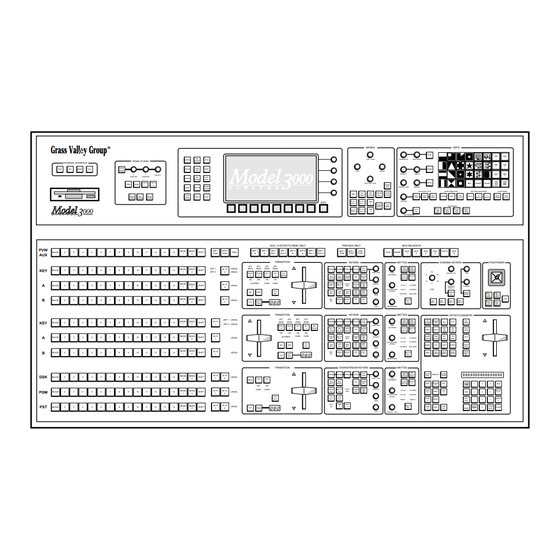
Tektronix Grass Valley 3000 User Manual (284 pages)
Digital Production Switcher
Brand:
Tektronix
| Category:
Switch
| Size: 1 MB
Table of Contents
User Manual
1
Customer Support
2
Table of Contents
3
Preface
11
Welcome to the Model 3000
11
Organization of this Manual
12
How to Use this Manual
13
Conventions Used in this Manual
14
Button and Panel Knob References
14
Menu References
15
Keyer Menu
15
Soft Button and Soft Knob References
15
Section 1 - System Overview
17
Introduction
17
General Description
18
Standard Features
19
Optional Features
20
Physical Description
21
Signal Processor Frame
21
Power Supplies
22
Control Panel
23
Video and Key Inputs and Outputs
25
Inputs
25
Outputs
27
Functional Description
29
Overview
29
Video Processing
30
Description of Options
34
Dual Chroma Keyer
34
Borderline® Key Edge Generation
34
Secondary Wipe Generator
34
Safe Title/Action Area Generator
35
MIX/Effects Clean Feed
35
Frame Store
35
Effects Send
35
Tally Output
36
Tally Expansion
36
Remote Auxiliary Bus Control Panels
36
Chroma Key Auto Setup
36
Section 2 - Startup & Configuration
37
Startup & Configuration
37
Introduction
37
Powering up
38
Boot-Up
38
System Status
39
Status Menu
39
Software Setup
43
The Configuration Menu
43
Setting System Parameters
46
Setting the System Clock
48
Set Clock Menu
48
Configuring Inputs
50
Configuring Inputs
50
Inputs Menu
51
Setting Input Digital Resolution
52
Configuring External Key Sync
53
Configuring Key Setup
54
Mapping Crosspoints
55
Input Type
56
Formatting Chroma Key Inputs
58
Assigning GPI Inputs
59
Gpi Inputs Menu
59
Configuring Outputs
62
Setting Switcher Output Timing
64
Setting Output Digital Resolution
66
Configuring External Interfaces
68
Configuring External Interfaces
68
Setting Editor Port Parameters
69
Configuring a DPM
70
Video Connection (aux Buses and Return Inputs)
70
DPM Capabilities (Fixed and Pooled)
71
Control Connections
76
Configuring the DPM Interface
77
For a DPM-700
78
For Kaleidoscope
78
For Dveous
79
For Other Non-Poolable Dpms
79
Mapping DPM aux Buses
80
Mapping DPM Inputs
81
Mapping DPM Returns
82
Mapping Kaleidoscope Source Buttons
84
Configuring the Peripheral Interface
85
Assigning Peripheral Triggers
86
Configuring GPI Outputs
88
Formatting aux Buses
89
Setting User Preferences
90
Setting Shift Lock Operation
90
To Shift Lock a Bus
91
To Unshift Lock a Bus
91
Setting Keyer Preferences
92
Preview Prefs Menu
94
Setting Preview Preferences
94
Setting Beeper Preferences
98
Setting User-Defined System Defaults
99
Operating Notes
100
Field Dominance Selection
100
Use of Field Dominance
100
Using the Mask Draw Feature
101
Mask Draw Setup
103
Operating the Model 3000 with a DPM-700
104
To Enable the Model 3000
104
Operating the Model 3000 with Kaleidoscope
106
To Enable Kaleidoscope
106
To Enable the Model 3000
106
Joystick Override Programming
107
Remote aux Panel Joystick Override
107
Switcher Concepts
109
Section 3 - Switcher Concepts
110
Clear Working Buffer
110
CWB Modes of Operation
111
Auto Delegation
112
Crosspoint Bus
113
Transitions
114
Cut Transition
114
MIX Transition
114
Wipe Transition
116
Keys
117
Luminance Key
118
Linear Key
120
Preset Pattern Key
120
Shaped and Unshaped Video
121
Input Shaped and Unshaped Video
122
Output Shaped and Unshaped Video
122
Super Black
123
Chroma Key
124
Coring
126
Layering
127
E-MEM Effects Memory
128
Effects and Keyframes
128
Enables and Delegates
129
Enables and Delegates Button Tallies
130
Operation
130
Keyframing / Timelines / Effects Editing
131
Effects Editing Definitions
132
Timeline Menu
133
Manipulating Video Images
134
Effects Send (Option)
136
Frame Store (Option)
137
Section 4 - Switcher Operations
139
About this Section
139
Switcher Operations
139
Starting Conditions
140
Switcher Hardware Setup
140
Clearing the Switcher
142
Transitions - MIX/Effects Bus Operations
144
Background Cut
144
Background MIX
147
Wipe Operations
149
Background Wipe
149
Pattern Mixing
153
Learning User Wipes
154
Fade to Black
157
Setting Transition Rates
158
Background and Matte Generator Operations
160
Matte Selection
160
Super Black
160
Luminance and Linear Keying Operations
162
Key Transition
166
Preset Pattern Keying Operations
167
Layered Mode Operations
170
Chroma Keying Operations
171
Auto Chroma Keying Procedure
172
Auto Setup
174
Basic Manual Adjustment
175
Optimization Adjustments
177
E-MEM (Effects Memory) Operations
181
New Operational Mode Available - Version 5.1 and Later
182
Normal Mode
182
Learn a Register
183
Recall a Register
184
300 Style Mode - 3-M/E Switchers Only
185
Operational Defaults in Either Mode
185
Setup
186
Basic E-MEM Operations
186
Enabling E-MEM Register Levels
186
Learn Enables
187
Storing an Effect
188
Recalling an Effect
188
Learning Effects Dissolve Transitions
189
E-MEM Learn Sequence Operations
190
Undo Function
191
Keyframe Operations
192
Setup
192
Basic Editing
192
Learn Keyframes
193
Advanced Keyframe Editing
194
Version 5.2 and Later Software Changes
196
Working with Keyframe Timelines
198
Setting and Adjusting Start Times
199
Zoom and Pan Timeline Effects
200
Cut, Copy, and Paste Keyframes
201
Constant Duration Mode
203
Effects Editing with Get and Put
203
Using Path Types to Change an Effect
204
Effects Send Operations (Option)
206
Setup
206
Effects Send Looping Mode
208
Effects Send Non-Looping Mode
208
Frame Store Operations (Option)
209
Setup
209
Output Routing
209
Still Image Storage
210
Building a Recursive Effect
210
Mask Store
211
Video and Key
211
Freeze Mode
212
Frame Store Field Modes
212
Field / 4 Field
212
Field 1 / Field 2
212
Grab Mode
213
Dropshadow Mode
213
Repositioning
214
Mosaics
214
Pseudo Color
214
Filter
214
Crop
214
Floppy Disk Drive Operations
215
Format Diskettes
215
Creating Directories and Files
216
Store and Name an E-MEM File
216
Store and Name a Configuration File
217
Deleting Files and Directories
220
Viewing (Listing) Files and Directories
220
Appendix A - Shaped and Unshaped Video
223
Introduction
223
What Are Shaped and Unshaped Video
223
Input Shaped and Unshaped Video
224
Configuring the Input
225
Examples of Operation with Shaped and Unshaped Fill Video
226
Correct Input Configuration
228
Correct Operation with Shaped Fill Video
228
Correct Operation with Unshaped Fill Video
230
Incorrect Input Configuration
231
Incorrect Operation with Shaped Fill Video
231
Incorrect Operation with Unshaped Fill Video
233
Output Shaped and Unshaped Video
235
For the Model 3000
235
Outputs Menu
236
For the Model 4000 or Model 2200
237
Installation Considerations
238
Appendix B - Keyframe Facts
241
Keyframe Timelines
241
Master Timeline
241
Enables and Delegates
243
Keyframe Path Control
245
Tension, Continuity, and Bias Controls
245
Path Vectors
246
Tension Control
247
Continuity Control
250
Bias Control
253
Appendix C - Super Black
257
Definition of Super Black
257
Objective
257
Limitations
257
Usage
258
Using the Super Black Output
258
Generating Super Black
259
First Method
260
Second Method
260
Reconstructing the Signal
261
Glossary
263
Advertisement
Tektronix Grass Valley 3000 Installation And Service (254 pages)
Video Production Switcher
Brand:
Tektronix
| Category:
Switch
| Size: 2 MB
Table of Contents
Customer Support
2
Table of Contents
3
Important Safety Notices
9
Symbols and Their Meaning in this Manual
9
Danger
10
Warnings
10
Cautions
11
Power Cord Notices
11
North American Power Supply Cords
11
International Power Supply Cord
11
EMC Regulatory Notices
12
Section 1 - System Overview
13
Introduction
13
System Description
13
Available Options
15
Input Modules
15
Output Modules
16
Crosspoint Name Displays
16
Frame Store
17
Effects Send Matrix
17
Dual Chroma Keyer
18
Chroma Key Auto Setup
18
Borderline Key Edge Generation
19
Secondary Wipe Generator
19
Safe Title/Action Area Generator
20
Remote Auxiliary Bus Control Panels
20
Tally Expansion Chassis
20
Power Supplies
21
Control Panel Power Supplies
21
Frame Power Supplies
21
Extender Modules
21
Physical Description
22
Control Panel
22
Signal Frame
22
System Specifications
24
Section 2 - Installation
31
Introduction
31
Unpacking
32
Pre-Installation Procedures
33
Items Required but Not Supplied
33
Physical Specifications and Installation Requirements
33
Environmental Characteristics
34
Power Requirements
34
Safety Requirements
34
Installation
36
Model 3000-2 Control Panel Installation
36
Model 3000-2 Control Panel Console Dimensions
36
Inserting the Model 3000-2 Panel
38
Model 3000-3 Control Panel Installation
39
Model 3000-3 Control Panel Console Dimensions
41
Inserting the Model 3000-3 Panels
44
Signal Processor Frame Installation
45
Signal Processor Frame Power Supply Installation
48
Redundant Power Supply Installation
51
Review
53
Module Locations
54
Input Modules
54
Output Modules
56
Interconnect Adapters
56
RF/EMI Strips on Input/Output Modules
59
Cable Connections
60
Model 3000-2 Control Panel Control Connections
61
Model 3000-3 Control Panel Connections
62
Input Signal Connections (Video and Key)
64
Analog Video Connections
64
Digital Video Connections
64
Serial Digital Connections
64
Parallel Digital Connections
65
Reference Input Connections
66
Output Signal Connections
66
Frame Communications Connections
67
GPI Connections
68
GPI Inputs
68
Configuring GPI Inputs and Outputs
69
GPI Outputs
69
Connecting to Kaleidoscope
70
Connecting to a Krystal Digital Picture Manipulator
71
DPM Logical Channel Tally
73
DPM Logical Channel Tally Example 1
74
DPM Logical Channel Tally Example 2
75
DPM Logical Channel Tally Menu Setup
76
Power Connections
77
Connecting the Control Panel to the AC Power Source
77
Connecting the Frame Power Supply to the AC Power Source
77
For 220-Volt Operation
77
For 110-Volt Operation
78
Powering up
82
Preliminary Checks
82
Power-On
82
Redundant Power Supply Voltage Adjustments
84
System Setup
86
Setting Vertical Blanking Range
86
Setting Preview Blanking Switch
86
Checking Auto-Timed Analog Inputs
88
What Is Autotiming
88
Installation of Options
89
Crosspoint Name Displays (Model 3000-3 Only)
89
Input Display Option Board Installation
89
Input Display Option Kit Contents
89
Tally Output Option
90
Tally Output Module Switch Settings
91
Tally Output Connector Pinouts
94
Tally Expansion Option
95
Installation of Tally Expansion Option
95
Chassis Installation
96
Control Cable Installation
97
Installing Modules
98
Tally Output Cable Installation
98
Setting Tally Module Switches
99
Turning on the Tally Expansion Option
99
Optional Remote aux Control Panels
100
Disabled Buttons
101
High Tally
101
Minimum Requirements
101
Cable Installation
102
Chop
102
Joystick Override
102
Remote aux Panel Installation
102
Switcher Interconnect Cable
103
Changing the Joystick Override Programming
104
Joystick Override Cable Installation
104
Joystick Override Programming
104
Address Switches
105
Bus to be Controlled (Bus Enable) Switches
105
Chop Enable Switch
105
Setting Rear Panel Switches
105
Delegate Lock Switch
107
Force High Tally Switch
107
Remote aux Panel Installation
107
Remote aux Panel Power Supply Installation
107
Test Mode Switches
107
Remote aux Panel Lens Chip Installation
108
Hardware Requirements
110
Installation for UD and KT Series
110
Mask Draw Tablet Installation
110
Installation for SD Series
111
Configuring Your System Software
112
Troubleshooting
113
Section 3 - Functional Description
115
Introduction
115
Functional Description
115
System Configuration
116
System Overview
117
Signal Formats
120
Analog Video
120
SMPTE Composite Parallel Digital
120
Timing
120
SMPTE Composite Serial Digital
121
Clock (SYS2 CLK)
122
Input Clock (SYS1 CLK)
122
Input Fast Clock
122
Output Fast Clock (OFCLK)
122
Input and Output Signals
124
Input Modules
124
Analog 10-Bit Auto-Timing Input Module
124
Composite Digital D2 Bit-Parallel Input Module
124
Composite Digital D2 Bit-Serial Input Module
124
RGB Input Module
124
Output Modules
125
Gpi
125
Editor Port
126
Tally Relay Option
126
Communication Inputs and Outputs
127
DPM Ports
127
P E Ri Phe Ra L Bus II
127
Signal Processor Frame Description
129
Signal Processor Overview
129
Control Section
129
Input Section
129
Output Section
129
Input Section
130
Video and Effects Section
133
Chroma Keyers
134
Keyers, PGM/PST and Borderline
134
Key Source
135
Luminance Keys
135
Borderline
136
Key Mask
136
Matte Generation on the Keyers and PGM/PST Modules
137
Matte Modulation on the Keyers and PGM/PST Modules
137
Mixer and Wipe Generator Modules
138
Clean Feed
139
Frame Store Option
139
Preset Wipes
139
Effects Send Module Option
140
Frame Stores Provide the Following Features
140
Output Section
141
Control Section
143
Control Panel CPU Module
143
Peripheral Utility Processors (Pups)
143
Control Processing by the Signal Processor Frame
146
Data Transfer to the Frame
146
Status Terminal
147
MIX Effects Modules
148
Sync Generator and Preview Module
148
Black and Test Generators Section
150
Sync Generator Section
150
Preview Section
151
Analog Composite Input 10-Bit
152
Composite Parallel Digital Input
152
Composite Serial Digital Input
152
Input Modules
152
Crosspoint Modules
156
M/E Keyer Module
157
Keyer Module (Continued)
162
Effects Send Module Option
165
M/E Mixer and Primary Wipe Module
166
PGM/PST and Dual DSK Module
169
Output Modules
172
Analog NTSC Composite Output
172
Composite Serial Output
174
Composite Parallel Digital Output
176
Secondary Wipe Option Module
178
Dual Component RGB Input Option Module
180
Dual Chroma Keyer Option Module
181
Controller Module
184
Control Panel Description
189
Control Panel Components
189
Model 3000-3
195
Control Panel Functional Operation
196
Model 3000-2
199
Model 3000-3
199
Peripheral Utility Processor Functional Operation
200
Power Supply Description
201
Control Panel
201
Signal Processing Frame
201
Signal Processor Frame Assembly
202
Section 4 - Maintenance
203
Introduction
203
Servicing Precautions
203
Powering down
203
Removing Circuit Modules
204
Repairing Circuit Modules
205
Servicing Procedures
205
Repairing Power Supplies
205
Power Supply Configurations
206
Frame Power Supply Replacement
206
Front Panel
207
Power Switch
207
Replacement of Individual Power Supply Assemblies
209
Configurations
209
Procedures
209
Replacement of Multi-Output Power Supply Assembly
210
Removal of Pioneer Multi-Output Supply
210
Installation of Todd Multi-Output Supply
212
Mount Terminal Block
212
Install Assembly in Frame
213
Wiring Diagram
214
Replacement of +5 Volt Power Supply Assembly
214
Removal of Pioneer +5 Volt Supply
214
Installation of Todd +5 Volt Supply
216
Wiring Diagram
220
Redundant Power Supply Voltage Adjustments
220
Replacement of Model 3000-2 Control Panel Power Supply(S)
223
Replacement of Model 3000-3 Control Panel Power Supply(S)
225
Control Panel Servicing
226
Control Panel Circuit Board Replacement
229
Pushbutton Lamp Replacement
231
Air Filter Cleaning
232
Frame Air Filter Cleaning
232
Frame Power Supply Air Filter Cleaning
234
Signal Processor Frame Circuit Module Replacement
235
Section 5 - Diagnostics
239
Introduction
239
Repairing Circuit Modules
240
Static Charges
240
Recommended Test Equipment
240
Required Reference Signals
240
System 3000 Service Philosophy
241
Fault-Isolation Diagnostics
241
Power up Diagnostics
241
Manual Video Path Testing
242
Remote Diagnostics
242
The Software Driven Video Path Diagnostics
242
Video Path Diagnostics
242
Manual Fault Isolation Procedures
243
Cabling and New Equipment Installation
243
CPU Run and Error Leds
244
Power Supplies
244
Reference Signals and Sources
244
Software Updates
244
Isolating Software Operating Faults
245
Isolating Control Panel Faults
245
Isolating Signal Processing Frame Faults
245
Isolating Remote aux Faults
246
Draining the Control Processor RAM
247
Advertisement
Related Products
Tektronix Keithley 3700A Series
Tektronix Keithley 3706A
Tektronix Keithley 3706A-S
Tektronix Keithley 3706A-SNFP
Tektronix KEITHLEY 3740
Tektronix Grass Valley 4000
Tektronix Phaser 300X
Tektronix Phaser 300i
Tektronix Phaser 300RX
Tektronix 308
Tektronix Categories
Test Equipment
Measuring Instruments
Amplifier
Portable Generator
Printer
More Tektronix Manuals
Login
Sign In
OR
Sign in with Facebook
Sign in with Google
Upload manual
Upload from disk
Upload from URL