Tektronix KEITHLEY 707B Quick Start Manual
Hide thumbs
Also See for KEITHLEY 707B:
- Reference manual (534 pages) ,
- Reference manual (555 pages) ,
- User manual (66 pages)
Table of Contents
Advertisement
Quick Links
Advertisement
Table of Contents

Related Manuals for Tektronix KEITHLEY 707B


Summary of Contents for Tektronix KEITHLEY 707B
- Page 1 Models 707B and 708B Quick Start Guide...
- Page 2 Safety precautions overvoltages often associated with local AC mains connections. Certain Keithley measuring instruments may be connected to mains. These instruments will be marked as category II The following safety precautions should be observed before using this product and any or higher.
- Page 3 Do not touch any object that could provide a current path to the common side of the circuit under The WARNING heading in the user documentation explains hazards that might result test or power line (earth) ground. Always make measurements with dry hands while standing on in personal injury or death.
-
Page 4: Power And Environmental Specifications
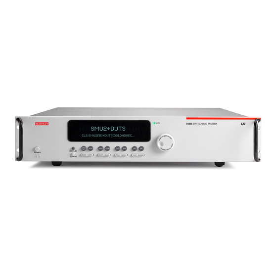
Power and environmental specifications For indoor use only. 100 V to 240 V , 50 Hz to 60 Hz Power supply (autosensing) 707B: 210 VA maximum Maximum VA 708B: 110 VA maximum Maximum 2000 m (6562 ft) above sea level Operating altitude 0 °C to 50 °C, 80% relative humidity up to 35 °C Operating... - Page 5 Introduction The Models 707B and 708B provide outstanding low‑current Complete documentation for the 707B and 708B instruments matrix capability and let you control up to 576 matrix is available for download on the Keithley web page at crosspoints in real time. Their large matrix format makes tek.com/keithley.
- Page 6 To unpack and inspect the instrument: 1. Inspect the box for damage. 707B documentation and accessories on top; 2. Open the top of the box. 708B documentation and accessories 3. Model 707B only: Remove the bag that contains the are under the packaging insert documentation and accessories.
- Page 7 5. Model 707B only: Remove the fixed rack mounting 7. Inspect the instrument for any obvious signs of physical hardware from the box. The parts are next to the damage. Report any damage to the shipping agent instrument in separate packaging. immediately.
- Page 8 You should have received the Model 707B or 708B Switching Matrix with the following accessories: 1. Model 707B only: Fixed rack mounting hardware. 2. Rack‑mount hardware (707B and 708B). 3. Ethernet cable. 4. TSP‑Link cable. ® 5. Power‑line cord. 6. Safety Precautions (not shown). 7.
-
Page 9: Connect The Instrument
Connect the instrument • Read and comply with the specifications of all instruments in the system. The overall allowed signal levels may be constrained by the lowest rated instrument in the system. For example, if you are using a 500 V power supply with Important test system safety information a 300 VDC rated switch, the maximum allowed voltage in This product is sold as a stand‑alone instrument that may... - Page 10 • Where possible, use automatic handlers so that operators WARNING are not required to access the DUT or other potentially hazardous areas. • Provide training to all users of the system so that they To prevent electric shock that could result in injury or understand all potential hazards and know how to protect death, never handle a switching card that has power themselves from injury.
- Page 11 To install a switching card in the Model 707B or 708B: Slot Covers Slot 1 1. Turn the instrument power off. 2. Position the instrument so that you are facing the rear panel. WARNING As described in the International Electrotechnical Commission (IEC) Standard IEC 664, the Model 707B and 708B switch cards are Installation Category I and must not be connected to mains.
- Page 12 5. Align the card edge into the card guide of the slot. 6. Slide in the card. For approximately the last ¼ inch, press in firmly to mate the card connector to the 707B or 708B connector. 707B rear panel slot 1 7.
-
Page 13: Install The Instrument
CAUTION All signal wiring to devices and instruments is done through the switch cards. Refer to the switch card documentation for additional information. Operating the instrument on an incorrect line voltage may cause damage to the instrument, possibly voiding Install the instrument the warranty. -
Page 14: Turn On The Instrument
Turn on the instrument To connect line power: 1. Make sure that the front-panel power switch is in the off (0) position. Turn on the instrument by pressing the front panel POWER switch to the on (|) position. 2. Connect the socket of the supplied power cord to the power connection (AC receptacle) on the rear panel. -
Page 15: Power-Up Sequence
Power-up sequence When the instrument is turned on, you should see: • Three dots • All segments of the displays light • All LED indicators light • A brief display showing “KEITHLEY Model 707B” or “KEITHLEY Model 708B” The entire power-up process takes approximately five seconds to complete. - Page 16 Test the instrument 4. To close a channel, push the navigation wheel to edit the slot and row, then turn the wheel to change the value. Push the navigation wheel to accept the displayed slot and row; this also activates edit mode for the column. To test the instrument for basic operation: Rotate the navigation wheel to change the column value 1.
- Page 17 These steps confirm basic functionality of your system. Please turn your system off now. The examples in the Models 707B and 708B User’s Manual demonstrate increasing levels of functionality of your 707B or 708B. We recommend that first-time users complete the appropriate examples from the User’s Manual.
- Page 18 FAQs What should I do if I see an error message when I turn the instrument on? If an error message is displayed, press a front‑panel key. The 707B or 708B attempts normal operation. Where can I find updated drivers? For the latest drivers and additional support information, see the Keithley Instruments support website.
-
Page 19: Next Steps
Next steps Refer to the Keithley Instruments website, tek.com/keithley, for support and additional information about the instrument, including the following documents: • The Models 707B and 708B User’s Manual for general information about the instrument and application examples that will help familiarize you with the instrument. - Page 20 Middle East, Asia, and North Africa Find more valuable resources at TEK.COM Australia* 1 800 709 465 +41 52 675 3777 Copyright © 2019, Tektronix. All rights reserved. Austria 00800 2255 4835 Tektronix products are covered by U.S. and The Netherlands* 00800 2255 4835 foreign patents, issued and pending.
Need help?
Do you have a question about the KEITHLEY 707B and is the answer not in the manual?
Questions and answers