Advertisement
Quick Links
Keithley Instruments
28775 Aurora Road
Cleveland, Ohio 44139
1-800-935-5595
tek.com/keithley
Introduction
This guide contains information on S46T relay installation and system configuration that is necessary after
installing new relays. To install a relay, refer to
applicable installation instructions.
Relay kits
Connection and wiring procedures in this document are intended for use by qualified
personnel only. Do not perform these procedures unless qualified to do so. Failure to
recognize and observe normal safety precautions could result in personal injury or death.
Use only the parts specified in the following table when servicing equipment. Use of improper
parts may expose the operator to hazardous voltages that could result in personal injury or
death.
Relay kit
model number
(Description)
S46T-SPDT-KIT
(18 GHz SPDT)
S46T-SP4T-KIT
(18 GHz SP4T)
S46T-SP6T-KIT
(18 GHz SP6T)
S46T-SPDT-KIT-26
(26.5 GHz SPDT)
PA-913 Rev. B / December 2019
High Performance Relay Installation Guide
Relay
Kit parts summary
location
(Quantity)
1 to 8
SPDT unterminated relay (1)
SPDT spacer (1)
Connecting cable (1)
A to D
4-40 x 3/16 PPHSEM screws (2)
4-40 x 3/8 PFH screws (4)
SP4T relay (1)
Ribbon cable (1)
Mounting plate (1)
A to D
4-40 x 3/16 PPHSEM screws (2)
4-40 x 3/8 PFH screws (4)
SP6T unterminated relay (1)
Ribbon cable (1)
Mounting plate (1)
1 to 8
SPDT unterminated relay (1)
SPDT spacer (1)
Connecting cable (1)
*PPA-913B*
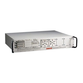
S46T Microwave Switch System
Relay kits
(on page 1) for a description of the kits and follow the
Keithley part
number
S40-0154
S40-SE05-307
SYS46-311C
4-40 x 3/16 PPHSEM
4-40 x 3/8 PFH
RL-282-2
CA-286-1
S40-N410-312
4-40 x 3/16 PPHSEM
4-40 x 3/8 PFH
RL-282-1
CA-286-1
S40-N410-312
RL-308
S40-SE05-307
SYS46-311C
Installation
reference
SPDT relay 1 - 8
installation
(on page 3)
Relay A - D
installation
(on page 6)
Relay A - D
installation
(on page 6)
SPDT relay 1 - 8
installation
(on page 3)
1
Advertisement

Subscribe to Our Youtube Channel
Related Manuals for Tektronix Keithley S46T


Summary of Contents for Tektronix Keithley S46T
- Page 1 S46T Microwave Switch System High Performance Relay Installation Guide Keithley Instruments 28775 Aurora Road Cleveland, Ohio 44139 1-800-935-5595 tek.com/keithley Introduction This guide contains information on S46T relay installation and system configuration that is necessary after installing new relays. To install a relay, refer to Relay kits (on page 1) for a description of the kits and follow the applicable installation instructions.
- Page 2 S46T Microwave Switch System High Performance Relay Installation Guide Relay A - D S46T-SP4T-KIT-26 A to D 4-40 x 3/8 PFH screws (4) 4-40 x 3/8 PFH installation (26.5 GHz SP4T) SP4T unterminated relay (1) RL-312 (on page 6) Mounting plate (1) S40-N410-312 Ribbon cable (1) S46-U100-350A...
-
Page 3: Installation
S46T Microwave Switch System High Performance Relay Installation Guide Installation Turn off the power and disconnect the line cord before installing the new relays. Failure to turn off the power and disconnect the line cord before installing the relays may result in personal injury or death due to electric shock. - Page 4 S46T Microwave Switch System High Performance Relay Installation Guide You can install either relay type (terminated or unterminated) in any of the eight available locations. However, you will need to use the shorter relay spacer screws when installing relays on the right side of the instrument column.
- Page 5 S46T Microwave Switch System High Performance Relay Installation Guide Figure 3: Connect control wires to the SDPT relay 9. Install the relay mounting bracket using the screws removed in step 1. 10. Refer to the following table and figure in order to plug the wire connector into the appropriate circuit board connector.
- Page 6 S46T Microwave Switch System High Performance Relay Installation Guide Figure 4: Relay connector locations Relay A through D installation To install A through D relays 1. Refer to the following figure and remove the four screws securing the cover plate over the mounting hole where the new relay is to be installed.
- Page 7 S46T Microwave Switch System High Performance Relay Installation Guide Figure 5: Relay A through D installation 2. Refer to the following figure to connect and solder the supplied ribbon cable to the following relays: XFER relays (transfer relays); 26.5 GHz unterminated relays; MSPDT relays 3.
- Page 8 S46T Microwave Switch System High Performance Relay Installation Guide Figure 6: Connect control wires A through D relays PA-913 Rev. B / December 2019...
-
Page 9: System Configuration
S46T Microwave Switch System High Performance Relay Installation Guide System configuration After installing the new relays, you must program the S46 for the new relay configuration with the following command: :ROUT:CONF:CPOL <clist> <clist> is defined as follows: clist = (@0 | 3-6, 0 | 3-6, 0 | 3-6, 0 | 1, ... -
Page 10: Safety Precautions
Safety precautions The following safety precautions should be observed before using this product and any associated instrumentation. Although some instruments and accessories would normally be used with nonhazardous voltages, there are situations where hazardous conditions may be present. This product is intended for use by personnel who recognize shock hazards and are familiar with the safety precautions required to avoid possible injury. - Page 11 For safety, instruments and accessories must be used in accordance with the operating instructions. If the instruments or accessories are used in a manner not specified in the operating instructions, the protection provided by the equipment may be impaired. Do not exceed the maximum signal levels of the instruments and accessories. Maximum signal levels are defined in the specifications and operating information and shown on the instrument panels, test fixture panels, and switching cards.
Need help?
Do you have a question about the Keithley S46T and is the answer not in the manual?
Questions and answers