
Subscribe to Our Youtube Channel
Related Manuals for Tektronix Grass Valley 4000


Summary of Contents for Tektronix Grass Valley 4000
- Page 1 Installation and Service Grass Valley Model 4000 Digital Production Switcher Software Release 5.3 071-0163-00 First Printing: January, 1996 Revised Printing: February, 1998...
-
Page 2: Customer Support
The information in this manual is furnished for informational use only, is subject to change without notice, and should not be construed as a commitment by Tektronix, Inc. Tektronix assumes no responsibility or liability for any errors or inaccuracies that may appear in this publication. - Page 3 Tektronix—Grass Valley Products P.O. Box 1114 Grass Valley, CA 95945 916-478-3800...
- Page 4 Tektronix—Grass Valley Products P.O. Box 1114 Grass Valley, CA 95945 916-478-3800...
-
Page 5: Table Of Contents
Contents Important Safety Information Symbols and Their Meaning in This Manual ........Danger . - Page 6 Contents Section 2 — Installation Introduction ..............Unpacking .
- Page 7 Contents Frame Signal Connections ..........2-67 Analog Reference Connection .
- Page 8 Contents M/E Key 2 Mezzanine Board ......... 3-25 DSK Program Background Mezzanine Board .
- Page 9 Contents Servicing Frame Power Supplies ..........Model 4000 Power Supply Configurations .
- Page 10 Contents Appendix A — Jetta Power Supply Information Introduction ............. . . Power Supply Configurations .
-
Page 11: Regulatory Notices
Important Safeguards and Regulatory Notices Specific warnings and cautions will be found throughout the manual where they apply, but may not appear here. Please read and follow the important safety information, noting especially those instructions related to risk of fire, electric shock or injury to persons. -
Page 12: Danger
Safeguards and Notices Danger Electrical potential is still applied to some internal components even when the power switch/breaker is in the off position. To prevent electrical shock when working on this equipment, disconnect the AC line cord from the AC source before working on any internal components. -
Page 13: Cautions
Safeguards and Notices Cautions Use only specified replacement parts. Follow static precautions at all times when handling this equipment. Leave the back of the frame clear for air exhaust cooling and to allow room for cabling. Slots and openings in the cabinet are provided for ventilation. Do not block them. -
Page 14: Emc Regulatory Notice
Safeguards and Notices EMC Regulatory Notice FCC NOTICE This equipment has been tested and found to comply with the limits for a Class A digital device pursuant to Part 15 of FCC Rules. These limits are designed to provide reasonable protection against harmful interference in a commercial environment. -
Page 15: Section 1 - System Overview
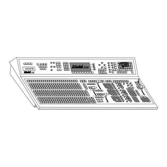
System Overview Introduction This section presents a general description of the Grass Valley Group Model 4000 Series Switching Systems, their basic architecture, and a list of video specifications. System Description The Model 4000 Series of digital production switchers includes the Model 4000-2A, the Model 4000-2B and the Model 4000-3. - Page 16 Section 1 — System Overview SPLIT SPLIT SPLIT Figure 1-1. Model 4000-2A Control Panel The Model 4000-2B switcher shown in Figure 1-2 provides 2 mix/effects systems with a Program/Preset mixer with Dual Downstream Keyer which can access up to 32 direct video/key sources at a time. Split Split Split...
- Page 17 System Description The Model 4000-3 switcher shown in Figure 1-3 provides 3 mix/effects systems with a Program/Preset mixer with Dual Downstream Keyer which can access up to 48 direct video/key sources at a time. Figure 1-3. Model 4000-3 Control Panel...
- Page 18 Section 1 — System Overview Modularity extends throughout the switching system, providing simple configuration and expansion to meet your present and future needs. The basic system consists of a Signal Processor Frame, Signal Processor Frame Power Supply, and a Control Panel, as shown in Figure 1-4.
-
Page 19: Available Options
Available Options Available Options This section provides brief descriptions of available options for the Model 4000 Series switchers. Input Modules The input formats may be a mix of component analog and component serial digital. A total of 64 inputs may be installed. A total of 12 optional input modules, 8 Component Analog Input Modules and 4 Component Serial Digital Input Modules can be installed. -
Page 20: Serial Outputs
Section 1 — System Overview Serial Outputs Serial Output Modules include the following outputs: Serial Output 1 (Slot D6) (All Models) Mask Switched Preview DSK Program Video DSK Program Key M/E 1 Program Video M/E 1 Program Key/Clean Feed Video (switchable) M/E 2 Program Video M/E 2 Program Key/Clean Feed Video (switchable) Serial Output 2 (Slot D5) (Model 4000-2A/B shipped before 1/96) -
Page 21: Timed Aux Outputs
Available Options Serial Output 4 (SlotD3) (All Models) Aux Bus 5a Video/Key Aux Bus 5b Video/Key Aux Bus 6a Video/Key Aux Bus 6b Video/Key Aux Bus 7a Video/Key Aux Bus 7b Video/Key Aux Bus 8a Video/Key Aux Bus 8b Video/Key Serial Output 5 (Slot D2) (All Models shipped after 1/96) Frame Store Video Frame Store Key... -
Page 22: Secondary Wipe Generators
Section 1 — System Overview Secondary Wipe Generators An optional Secondary Wipe Generator for each Mix/Effects provides a second wipe pattern for each of the M/E systems. With this option installed, two independent wipe patterns are allowed within each M/E. The output from the Secondary Wipe Generator can be mixed or non-additively mixed with the output from the primary wipe generator to create novel wipe patterns. -
Page 23: Borderline Key Edge Generation
Available Options BORDERLINE Key Edge Generation BORDERLINE® Key Edge Generators are optional for each keyer in the switcher. The BORDERLINE option is added by plugging a small sub-module onto the Keyer module of an M/E or the DSK. One sub-module can be installed for each of the two keyers in each M/E and one in each of the two keyers of the Down Stream Keyer (DSK) module. -
Page 24: Extender Modules
Section 1 — System Overview Extender Modules Two module extenders are supplied for use in troubleshooting Signal Processor Frame modules to the module level only. The longer extender is for the modules in front bays A (top) and B (bottom). The shorter one is for the input and output modules in rear bays C (top) and D (bottom). -
Page 25: Power Supplies
Available Options Power Supplies The Model 4000 is powered by two power supply assemblies. One assembly supplies the Control Panel. It is located inside the Control Panel tub. The Signal Processor Frame is powered by a single 19" standard rack mounted power supply assembly. -
Page 26: Physical Description
Section 1 — System Overview Physical Description Model 4000 Series electronic circuitry is contained on circuit modules in the Signal Processor Frame and Control Panel. Control circuitry is located in the Control Panel and in the top bay of the Signal Processor Frame. - Page 27 Physical Description Impeller Fan — Air flows up through the frame Outlets (Both sides & rear) Front Door Control and Signal Processing Modules (Front Bay A) Input and Output Modules and Options (Rear Bays C and D) Signal Processing and Option Modules (Front Bay B) Air Filter...
-
Page 28: System Specifications
Section 1 — System Overview System Specifications Specifications for the Model 4000 Systems are listed on the following pages. Refer to Section 2, Installation and Configuration, for information on the mechanical characteristics of the system. Specifications are provided for the following: Table 1-1—Power Specifications Table... - Page 29 System Specifications Table 1-2. Analog Input Video Requirements Characteristic Requirement Video Amplitude (Luminance channel) for 0.714 mV with/without setup or Primary Inputs 0.700 mV without setup (with or without sync) Maximum luminance Excursion +108 IRE peak positive Relative To Black level - 6 IRE peak negative (before clipping) Video Amplitude For Color...
- Page 30 Section 1 — System Overview Table 1-3. Serial Digital Input Video Requirements Characteristic Requirement Channel Coding Conforms to SMPTE RP-259M Aux Data Auxiliary data is blanked Connector 75 Ω Input Impedance Return Loss > 15dB 5 MHz to 270 MHz Autotiming Range ±18 µS Maximum Cable Length Equalized...
- Page 31 System Specifications Table 1-5. Serial Digital Output Specifications Characteristic Specifications Rise and Fall Times Between 400 pSec and 1.5 nSec across 75 Ω termination (Between 20% and 80% amplitude points) Jitter Timing of rising edges of data signal shall be within ±0.25 nSec of average timing of rising edges over a period of 1 line Channel Coding Conforms to SMPTE RP-259M...
- Page 32 Section 1 — System Overview Table 1-6. Video System Specifications (Analog In to Analog Out) Characteristic Specifications ≤ ± 0.2 dB to 5MHz, -18 at 6.75 MHz Frequency Response ≤ ± 8 nS to 5 MHz Group Delay error Field Rate Tilt <...
- Page 33 System Specifications Table 1-8. Environmental Specifications Characteristic Specifications Operating Ambient Temperature Range 0 - 40° C (32 - 104° F) Ambient Temperature for Specifications 20 - 30° C (68 - 86° F) Relative Humidity (Operating) 95% Maximum (Non-Condensing) 1-19...
- Page 34 Section 1 — System Overview 1-20...
-
Page 35: Section 2 - Installation
Installation Introduction This section describes the installation and setup of the Model 4000 Digital Switchers. The process of installing the Model 4000 is discussed in the following major areas: Unpacking Installing the Control Panel Installing the Signal Processor Frame in the rack Option Installation Cabling the equipment Power Connections... -
Page 36: Pre-Installation Procedures
Section 2 — Installation Pre-installation Procedures Before you physically install the Model 4000, there are certain considerations such as tools required, physical specifications, safety and power requirements you should be aware of. These considerations are covered in the following headings. Items Required but not Supplied The following is a list of items required for installation: Medium flat bladed screwdriver... -
Page 37: Power Requirements
Pre-installation Procedures Power Requirements Power requirements for the Model 4000 Control Panel and Signal Processing Frames are listed in Figure 2-2. The Frame is shipped from the factory configured for 220 VAC operation. Table 2-2. Power Requirements Component Power Voltage Frequency Control Panel 300 Watts (max) - Page 38 Section 2 — Installation WARNING The Model 4000 Digital Signal Processor Frame weighs approximately 300 lbs (136 Kg) when fully configured. Provide appropriate equipment to support the Frame during installation. Do not lift the Control Panel, by the lid. The lid could open causing the unit to fall creating a hazard to personnel and/or damage to the equipment.
-
Page 39: Installation
Installation Installation The following procedures contain the instructions necessary to install the Control Panel, Signal Processor Frame, and Frame power supply. Procedures are also included for optional modules and cable installation. Before proceeding, read and understand all precautions and notes. Model 4000-2A/B Control Panel Installation This installation does not require countersunk or beveled edges. -
Page 40: Model 4000-2A Cutout Dimensions
Section 2 — Installation Model 4000-2A Cutout Dimensions Using the dimensions shown in Figure 2-2, make cutouts in the console to accommodate the Model 4000-2A Control Panel. Carefully place the Control Panel into the cutout and mark the pilot hole locations for the six anchor screws. -
Page 41: Model 4000-2B Cutout Dimensions
Installation Model 4000-2B Cutout Dimensions Using the dimensions shown in Figure 2-3, make cutouts in the console to accommodate the Model 4000-2B Control Panel. Carefully place the Control Panel into the cutout and mark the pilot hole locations for the six anchor screws. Note that the ends of the panel tub have been designed to grasp for removal. -
Page 42: Model 4000-2 Rear Cable Clearance
Section 2 — Installation Model 4000-2 Rear Cable Clearance Using the dimensions shown in Figure 2-4, make cutouts in the rear of the console platform appropriate for your switcher model. Panel Connectors- Leave This Area Clear For Cables (Model 4000-2A) Mounting Surface Redundant... -
Page 43: Model 4000-3 Control Panel Installation
Installation Model 4000-3 Control Panel Installation A full flush-mount installation requires countersunk edges. The Panel enclosures (upper and lower tubs) slip into the cutout from the top, are fitted into the routed openings, and secured by 27 screws inserted through overhanging flanges at the front, rear, and sides of the tubs. -
Page 44: Model 4000-3 Control Panel Console Dimensions
Section 2 — Installation 0.375" (1.0 cm) 0.50" (1.25 cm) 9.50" (24.1 cm) 10.2 " (25.9 cm) 0.375" (1.0 cm) 0.2" (0.5 cm) 6.50" (16.5 cm) 3.625" 4.157" 0.375" 0.22" (9.2 cm) (10.6 cm) (1.0 cm) (0.5 cm) 17° 8.625" (21.9 cm) 0.50"... - Page 45 Installation 53.125" (134.8 cm) .5" by .375" Notch .5" by .375" Notch (1.25 by 1.0 cm) (1.25 by 1.0 cm) Rear 0.375" 0.375" (1.0 cm) (1.0 cm) Limits of Upper Control Panel Cutout 9.625" Area (23.5 cm) 0.188" (0.5 cm) Front .4"...
- Page 46 Section 2 — Installation 4. Carefully place the Upper Control Panel into the cutout (do not lift the control panel by the lever or transition arms) and mark pilot hole locations for the 12 anchor screws. Optional Interconnect Interconnect Cable Area Cable Area 2.0"...
-
Page 47: Inserting The Model 4000-3 Panel
Installation WARNING Clearance required between the hinge edge of both Control Panel tubs and the finished edge of the console increases as the panel lid is opened (full flush installation). Before marking the pilot holes, carefully open the lid on both panels and observe that sufficient clearance is allowed. -
Page 48: Pushbutton Lens Chip Installation
Section 2 — Installation Pushbutton Lens Chip Installation The primary crosspoint pushbuttons on the control panel are designed so lens chips can be inserted to label the inputs assigned to each crosspoint. An envelope containing a set of printed lens chips is shipped with the control panel. Make sure not to throw away the lens chips inadvertently. -
Page 49: Control Panel Option Installation
Installation Control Panel Option Installation These instructions are provided for installing the Redundant Control Panel Power Supply and the Model 4000-3 Input Readout Display if these options have been ordered after your original switcher installation. If you ordered either option with your original switcher, the options have already been installed and you may skip these steps. - Page 50 Section 2 — Installation NOTE: You may choose to install the redundant supply power into a different ac source than the primary power supply; however, doing this is not required. 11. Reinstall the ac power cord for the primary supply into its ac source. 12.
-
Page 51: Model 4000-3 Redundant Control Panel Power Supply
Installation Model 4000-3 Redundant Control Panel Power Supply To install the redundant Control Panel power supply in a Model 4000-3 control panel proceed as follows: Open the lower Control Panel tub and turn the AC power switch on the front of the primary supply to the OFF (Ø) position. - Page 52 Section 2 — Installation Line up the holes in the redundant supply case with the holes in the back of the panel and install the supply with the screws provided. Attach the control cable from the redundant supply to the vacant connector (J12) on the Distribution Board (068986) mounted to the right of the supply.
-
Page 53: Model 4000-3 Input Readout Display Panel
Installation Model 4000-3 Input Readout Display Panel The Input Readout Display option consists of three Readout Display circuit boards attached to three bracket assemblies; each providing eight 4-character readouts. The bracket assemblies attach to the inside of the accessory panel above the readout windows at the lower left of the Model 4000-3 upper accessory panel. - Page 54 Section 2 — Installation Three different length ribbon cables are provided for connecting the readout display circuit boards to the Control Panel CPU Board (Assembly Number 068985) mounted on the inside of the upper accessory panel. Install the following cables from the Readout Display circuit boards to the indicated connectors on the CPU board as shown in Figure 2-13 and described below.
-
Page 55: Signal Processor Frame Installation
Installation Signal Processor Frame Installation NOTE: The Signal Processor Frame must be installed before either of the power supplies. When planning your installation, ensure that the Frame will be installed high enough in the equipment rack to allow 7 rack units for the installation of the Frame Primary Power Supply (and another 7 rack units for the optional redundant Power Supply, if purchased) below it. - Page 56 Section 2 — Installation NOTE: The Frame is shipped with a protective metal plate on the bottom. Leave the plate in place to protect the power cables until the Frame is mounted in the rack. 1. Ensure that all packing foam, strapping, and tape is removed from the Frame before installing the Frame in the rack.
- Page 57 Installation Signal Processor Frame front Note: Front Door not shown for clarity Secure bolts through Frame (8 each side) into Rack Install Standard Power Supply Assembly and Optional Redundant Power Supply after Signal Processor Frame is installed in Rack (ensure shipping plate has been removed from bottom of Signal Processor Frame)
-
Page 58: Signal Processor Frame Power Supply Installation
Section 2 — Installation Signal Processor Frame Power Supply Installation The Primary Power Supply must be mounted immediately below the Signal Processor Frame in the rack. If you are installing an optional Redundant Power Supply, it must be located immediately below the Primary Power Supply. Verify that you have allowed enough rack space (7 rack units for each supply) before proceeding. -
Page 59: Model 4000-2A/B Only-Determining 110V Or 220V Ac Operation
Installation Before installing your power supply, you will need to determine the type of supply units you have. To do this: Locate the assembly number sticker on the back of the power supply frame. Systems with Pioneer power units will have power supply frames numbered 098901-00 or -01. - Page 60 Section 2 — Installation In the center section, disconnect the incoming AC power wires from the left and right sides of the terminal block (see Figure 2-15). Remove 10 AWG Remove Power Cord Nut and (3 wires) and Jumper Hardware Wire Brown Blue...
- Page 61 Installation must be in compliance with the National Electrical Code and any applicable local codes. Install 3-Wire Install Cable or 6 AWG Cable Flexible Conduit With 6 AWG Wire "Line" Directly From "Safety Ground" Circuit Breaker "Neutral" Install 3/4 In. Conduit Fitting in Cable Hole Brown...
-
Page 62: Frame Fan Jumper Settings
Section 2 — Installation Frame Fan Jumper Settings There is a jumper on a small circuit board (064851) in the fan assembly at the top of the Signal Processor Frame in each Model 4000 Switcher. This jumper must be in the correct position for proper operation of these power supplies. If your switcher has been shipped directly from the factory, this jumper setting will be correct. - Page 63 Installation Mount the rack sections of the slides to the front and back of the rack and secure them in place with the appropriate screws as illustrated in Figure 2-17. The mounting ears at the front of the slides should mount to the inside surface of the rack rail.
- Page 64 Section 2 — Installation Secure the front of the Power Supply assembly to the rails by installing the appropriate 1/4” (6.4 mm) length rack screws. (Use optional [not supplied] flat nylon washers with the rack screws to protect the equipment finish.) The finished power supply installation will appear as illustrated in Figure 2-14.
- Page 65 Installation 12. Refer to Figure 2-19. Connect the two large black cables running down from the right rear of the Signal Processor Frame to the right (Pioneer) or bottom (Todd) stud. If you are only installing a primary supply, secure with the nut and lock-washer removed previously.
-
Page 66: Redundant Frame Power Supplyinstallation
Section 2 — Installation CAUTION Do not power up until you reach the “Power Up” section later in this procedure. 16. If you are only installing a primary power supply at this time, skip the Redundant Frame Power Supply Installation section below. Redundant Frame Power SupplyInstallation The following procedure is provided for installing a redundant power supply during an initial switcher installation and also for adding a redundant power... - Page 67 Installation WARNING To reduce the risk of electric shock, do not perform any servicing other than that contained in the operating instructions unless you are qualified to do so. Perform the following procedure to install the Redundant Power Supply. Ensure that the Primary and Redundant Power Supplies are disconnected from all power sources.
- Page 68 Section 2 — Installation Primary Power Supply Signal Processor Red Cables from Processor Primary Power Supply Lock Black Cables Washers Nuts from Processor If Present, Remove Lock Washers Connector Cover Plate Stand-offs From Primary If Present, Power Supply Remove Slot Cover Plate From Primary Power Supply...
- Page 69 Installation Signal Processor Red Cables from Processor Lock Primary Washers Power Supply Nuts Black Cables from Processor If Present, Remove Lock Washers Connector Studs Cover Plate If Present, From Primary Power Supply Remove Slot Cover Plate From Primary Power Supply Route Cables Down Through Slot in Top of...
- Page 70 Section 2 — Installation 10. Secure the cables by placing a lock-washer and hex nut (removed earlier) over each end of the cables. 11. Similarly, place the pair of new red cables over the right studs in the Primary and Redundant Power Supplies and secure the cables with lockwashers and hex nuts.
-
Page 71: Frame Module Installation
Installation Frame Module Installation The Model 4000 switcher is shipped fully configured with all the standard and ordered optional modules already installed in the Signal Processor Frame. The Frame is divided into four “bays”, labeled Bay A (top front), Bay B (bottom front), Bay C (top rear) and Bay D (bottom rear). - Page 72 Section 2 — Installation The modules in the rear C and D Bays are removed by first removing the two screws at the top and bottom of each module, then pulling up on the upper and lower metal ejectors to release the module. Pull the module out slowly. Refer to Figure 2-23.
-
Page 73: Frame Module Locations
Installation Frame Module Locations On the following pages refer to the figures listed below for the module locations in each bay. NOTE: There are two versions of Model 4000 Signal Processor Frames covered in this manual; frames shipped before January, 1996 for all model switchers (Matrix 094800-00) and those modified for the Model 4000-3 (Matrix 094803-00). - Page 74 Section 2 — Installation B16 B17 B10 B11 B12 B13 B14 B15 4000-2A/B — Bottom Card-Cage Bay B Figure 2-25. Lower Front Bay B Modules —4000-2A/B Before January, 1996 B16 B17 B10 B11 B12 B13 B14 B15 Model 4000-3 — Bottom Card-Cage Bay B Figure 2-26.
- Page 75 Installation EXPANDED SERIAL SERIAL SERIAL SERIAL ANALOG SERIAL SERIAL SERIAL SERIAL INPUT INPUT INPUT OUTPUT INPUT INPUT INPUT INPUT INPUT (9-16) (17-24) (25-32) (1-8) (33-40) (41-48) (49-56) (57-64) TALLY SERIAL SERIAL CONTROL REENTRY REENTRY (4000-3) PROGRAM GPI INPUTS GPI OUTPUTS ANALOG REF IN PREVIEW...
- Page 76 Section 2 — Installation SERIAL SERIAL SERIAL SERIAL SERIAL OUTPUT OUTPUT OUTPUT OUTPUT OUTPUT GAIN GAIN GAIN GAIN GAIN GAIN GAIN GAIN GAIN GAIN GAIN TALLY CONTROL (Matrix 094800-00) GAIN GAIN GAIN GAIN GAIN GAIN GAIN GAIN GAIN GAIN GAIN Serial Output Option For Frame Store...
-
Page 77: Optional Frame Module Installation
Installation Optional Frame Module Installation These instructions are provided for installing the Model 4000 Signal Frame options if they have been ordered after your original switcher installation. If you ordered any options with your original switcher, the options have already been installed and you may skip these steps. - Page 78 Section 2 — Installation NOTE: If you are installing Analog Input Modules in addition to Serial Input Modules, the use of Serial Reentry Modules is required. The Serial Reentry Modules install in the slots designated for the optional Serial Digital Input Modules at locations C8, C10, C11 and C12.
- Page 79 Installation Refer to Table 2-5 below and Figure 2-28. for the correct module installation locations. The Analog Input Modules are installed into Slots D-10 through D-17 of the D Bay. The Serial Reentry Modules are installed into cells C8, and C10–C12 of the C Bay where the optional Serial Input Modules would normally be installed.
- Page 80 Section 2 — Installation Chroma Key Input Modules— The Dual Analog Component Chroma Key Input option includes up to three Chroma Key Input Modules (064817) with mezzanine boards (064837), each with two full bandwidth component analog inputs that can be routed to any Chroma Keyer in the system. The Chroma Key Input Modules reside in the lower rear D Bay in slots D7, D8, and D9.
-
Page 81: Serial Output Module Options
Installation Serial Output Module Options Each Serial Output Module (064821) option has eight different output signals (2 BNCs per output for a total of 16 BNCs on each module). The cell locations and the output signals available for each optional module are given below and shown in Figure 2-28. -
Page 82: Effects Send Option
Section 2 — Installation Serial Output 4 (SlotD3) (All Models) Aux Bus 5a Video/Key Aux Bus 5b Video/Key Aux Bus 6a Video/Key Aux Bus 6b Video/Key Aux Bus 7a Video/Key Aux Bus 7b Video/Key Aux Bus 8a Video/Key Aux Bus 8b Video/Key Serial Output 5 (Slot D2) (All Models shipped after 1/96) Frame Store Video Frame Store Key... -
Page 83: Borderline Key Edge Generator Option
Installation The parameters for various Chroma Keying functions must be defined in the main menu panel. These menus appear under the Chr Key button. Refer to the Model 4000 User’s Guide (TP0790) and Operation Reference (TP0764) Manuals for detailed information. BORDERLINE Key Edge Generator Option The BORDERLINE option consists of one mezzanine module (064909) for each keyer. -
Page 84: Secondary Wipe Pattern Generator Options
Section 2 — Installation Secondary Wipe Pattern Generator Options There are two Secondary Wipe Pattern Generator options for the Model 4000 series: The Secondary Wipe Pattern Generator for the Mix/Effects systems Secondary Wipe Pattern Generator for the Program/Preset Mixer and the DSK (Model 4000-2A only). -
Page 85: Look Ahead Preview Option
Installation SECONDARY WIPE MEZZANINE PRIMARY WIPE MEZZANINE LOOK-AHEAD PREVIEW MEZZANINE Figure 2-30. Secondary Wipe and Look Ahead Preview Option Installation The parameters for Secondary Wipes must be set in the main menu panel. These menus appear under the main Wipe pushbutton. Refer to the Model 4000 User’s Guide (TP0790) and Operation Reference (TP0764) Manuals for detailed information. -
Page 86: Tally Control Module Option
Section 2 — Installation Tally Control Module Option The Tally Control Module Option provides relay closures for on-air outputs for each of the mix/effects buses in the Model 4000 (64 tally relay outputs). There are also tally outputs for the M/E 1, M/E 2, and M/E 3 (4000-3 only) reentries. - Page 87 Installation GVG® 064808– TALLY CONTROL REMOVE JUMPER TO ISOLATE TALLY COMMON A AND TALLY COMMON B Figure 2-31. Tally Output Module Switch and Jumper Location When Mode 4 (Individual Bus Iso Tally) is selected, the remaining six banks of switches on the board (Switches S2–S7) select the switcher’s internal buses to be used as tally sources (see Table 2-8).
- Page 88 Section 2 — Installation Table 2-8. Individual Bus Enable Switch Settings Switch Switch Switch Function Switch Function PGM Video Bus M/E 3 Key 1 Video Bus PGM Key Bus M/E 3 Key 1 Key Bus* PST Video Bus M/E 3 Key 2 Video Bus* PST Key Bus M/E 3 Key 2 Key Bus* DSK 1 Video Bus...
-
Page 89: Timed Aux Output Option
Installation After setting the Tally Control Module switches, install the module by following the steps listed below: Remove the blank plate, if installed, and slide the Tally Control Module into Slot D1 of the lower rear D Bay for switchers shipped before January, 1996 (Matrix 094800-00) or Slot C5 of the upper rear C Bay for switchers shipped after January, 1996 (Matrix 094803-00). -
Page 90: Remote Aux Panel Option
Section 2 — Installation Remote Aux Panel Option The Remote Aux Control Panel Option allows you to control the Model 4000’s aux buses from a remote location. As many as 32 Remote Aux Panels can be daisy- chained to the switcher (see Cabling Information later in this section). There are three Remote Aux Panel configurations available, identified by the number of rack units (RUs) each occupies in the equipment rack. - Page 91 Installation Setting Rear Panel Switches — The Remote Aux rear panel includes a number of switches that control operating modes, such as address, bus enable, delegate enable, and test mode. Settings of these switches are explained below (Figure 2-33). FORCE HIGH TALLY PANEL ADDRESSES BUS TO BE CONTROLLED * Panel Addresses 32 and...
- Page 92 Section 2 — Installation Address Switches— Set the address of the Remote Aux Panel (0 through 31) using the switches marked PANEL ADDRESS on the right rear of the panel (see Figure 2-33). The seven switches have 128 possible combinations; however, only five of the switches may be used (1-16).
-
Page 93: Frame Store
Installation Delegate Logic Switch —On the 3-RU panel, the DEL LOGIC switch controls the functioning of the aux buses that are not selected: DEL LOGIC Switch OFF: If a BUS ENABLE switch is OFF, the associated Delegate button on the panel can be selected and the source button selected for that bus will light but cannot be changed. -
Page 94: Mask Draw Tablet Option
Section 2 — Installation Mask Draw Tablet Option The following WACOM graphics tablet models are supported (Grass Valley does not supply the tablet): KT-0405-R “ART PAD” (PC compatible version) UD—XXXX—R (Any PC-compatible UD-series tablet) UD-608-R “ART Z” (PC compatible version) SD series (these tablets are now obsolete;... -
Page 95: Installing Sd Series Tablet
Installation Installing SD Series Tablet Connect the graphics tablet to the input port on the back of POINTING DEVICE the switcher Control Panel. The Control Panel CPU Board RS-232 jumper blocks must be set to the “DTE” position. Model 4000-2: Open the Control Panel lid and locate the Control Panel CPU Board. -
Page 96: Cable Connections
Section 2 — Installation Cable Connections This section describes the cabling of the Model 4000 system components. You need not follow the specific sequence of steps presented here; however the procedures do provide a reference for ensuring that all connections are properly made. Cabling is described in the following sequence: Control Panel Connections Connection of the control cables from the Control Panel to the Frame... -
Page 97: Control Panel Connections
Cable Connections Control Panel Connections The control panel communicates with the Signal Processor Frame over RS-422 data lines–one per M/E plus a flip/flop mix data link. All of the links are contained in a single RP125 parallel digital cable that may be up to 300 meters (985 feet) long. -
Page 98: Model 4000-2A/B Control Cable
Section 2 — Installation Model 4000-2A/B Control Cable Connect the interconnect control cable to the connector marked J1 on the rear of the Control Panel as shown in Figure 2-35. Connect the other end of the interconnect control cable to J1 (PANEL) on the COM I/O Module in the top rear bay (Slot C3) of the Signal Processor Frame illustrated in Figure... - Page 99 Cable Connections Connect the other end of the Frame Communication cable to J1 (PANEL) on the COM I/O Module in the top rear bay (Slot C3) of the Signal Processor Frame illustrated in Figure 2-36. This cable length may be extended to a maximum of 300 meters.
-
Page 100: Status Terminal Connections
Section 2 — Installation Status Terminal Connections The Status Terminal connector (labeled “MAINTENANCE”) on the rear of the Control Panel allows the connection of a VT-100 (type) terminal to be connected to the Model 4000. The terminal is used to monitor system status and for maintenance purposes. -
Page 101: Frame Signal Connections
Cable Connections Frame Signal Connections Analog Reference Connection Connect an analog signal such as color black or any other stable analog signal to either J5 or J6, ANALOG REF IN, on the Com I/O Module in Slot C3. Terminate any unused BNC connectors. Input Signal Connections (Video and Key) The Model 4000 allows up to 64 video/key inputs to be connected. -
Page 102: Output Signal Connections
Section 2 — Installation Analog Input Connections— There are two types of optional analog inputs: component analog inputs (video and key) and external chroma key inputs. Formats accepted by the system for the analog inputs include the following: RGB (50 or 60 Hz, Setup or No Setup) Beta MII (50 or 60 Hz) EBU/SMPTE... - Page 103 Cable Connections Table 2-9. Analog Output Module Setting J5, J6, J9, J11 Format J4 (Y) J8 (R-Y) J10 (B-Y) DAC Mezz. Selection Analog Module DAC Mezz. DAC Mezz. DAC Mezz. Color Diff. EBU/SMPTE No Setup RGB .714 v No Setup b &...
- Page 104 Section 2 — Installation Coarse adjustment of the format voltage levels are set by jumper selection; however, you may need to fine tune these levels using the gain adjustments on the DAC Mezzanines. Place the Analog Output Module on the I/O Module Extender (064834), and select 100% Color Bars as the Program and Preview switcher output.
- Page 105 Cable Connections COLOR DIFFERENCE FORMATS –– –– –– –– -300 -300 –– -286 -300 –– -300 R–Y: -350 -467 -467 -467 -350 -324 -324 B–Y: -350 -467 -467 -467 -350 -324 -324 –– –– –– –– –– Y with –– ––...
- Page 106 Section 2 — Installation RGB FORMATS -286 -300 -286 -286 -300 -286 -286 -300 -286 NOTE: All voltage levels are in millivolts. Figure 2-38. RGB Format Chart 2-72...
- Page 107 Cable Connections Timed Aux Output Connections— The Timed Aux Output module allows eight connections from the Model 4000 to your Krystal or other digital effects device BNC input connectors. These inputs may be independent video or video/key pairs. Connectors J1, J5, J9, and J13 are video outputs. Connectors J3, J7, J11, and J15 may be used as video or key outputs.
- Page 108 Section 2 — Installation Serial Digital Output Connections— Serial Digital Output Modules allow connection to the serial digital output signals from the Model 4000. The signal type of each output is hardwired according to the slot ID and is listed on the designation strip on the back of the Signal Frame (above the C Bay).
- Page 109 Cable Connections SERIAL OUT 2 SERIAL OUT 1 SERIAL OUT 3 SERIAL OUT 4 NOT USED SERIAL OUT 5 CELL D5 CELL D6 CELL D4 CELL D3 CELL D2 CELL D1 ME3 PGM AUX 1A F/STORE AUX 5A MASK VIDEO F/STORE AUX 5B AUX 1B...
-
Page 110: Frame Communications Panel Connections
Section 2 — Installation Frame Communications Panel Connections You can connect external devices such as Video Production Editors, Digital Effects Systems such as GVP’s Krystal, Kaleidoscope, and DPM-700, GPI connections, Tally Expansion, and a maintenance terminal to the Model 4000 switcher. These are connected to the switcher via the Communications I/O Module, GPI Module, and the Expanded Communications Module, located at the C Bay of the Frame as shown in... -
Page 111: Video Production Editor Connections
Cable Connections Video Production Editor Connections The Model 4000 may be connected to video editors such as GVP’s VPE or Sabre series of editors. Attach the signal cable from the editor to the EDITOR port (J3) located on the Communications I/O Module in Slot C3 as shown in Figure 2-42. - Page 112 Section 2 — Installation Editor Port Jumper Settings— There are two sets of EDITOR port jumpers which are located on the Control Processor II module (064806) as shown in Figure 2-43. Jumper J15 sets the communication standard (RS-232 or RS-422); Jumpers J16, J17, and J18 set the EDITOR port termination (terminated or not terminated).
-
Page 113: Connecting To A Krystal Digital Effects System
Cable Connections Connecting to A Krystal Digital Effects System A typical Model 4000 and Krystal Digital Effects System connection is illustrated Figure 2-44. The Model 4000’s Timed Aux Bus video and key outputs are connected to the Krystal’s video and key inputs. (There is also an optional mask connection available with a Krystal option.) The Krystal’s modified outputs can then be connected to any of the Model 4000 physical inputs (1 to 64). -
Page 114: Connecting To Kaleidoscope
Section 2 — Installation Connecting to Kaleidoscope The Kaleidoscope Controller connects to the Model 4000 through an adapter cable (151022-00) and the Model 4000 RS-422 control cable (054602-16). See Figure 2-45. The Model 4000’s Aux Bus video and key outputs (numbered 1 thru 5) are connected to the Kaleidoscope Channel video and key inputs. -
Page 115: Connecting To A Dpm-700
Cable Connections NOTE: Standard length of the RS-422 cable is 16 meters (The cable length is indicated by the dash number on the end of the part number.) The maximum combined length of the adapter and RS-422 cables should not exceed 300 meters. The adapter cable connects between J17 at the rear of the Kaleidoscope Controller chassis, and the 9-pin D-type connector on the end of the RS-422 control cable. - Page 116 Section 2 — Installation Model 4000 Signal Processor Frame DPM-700 Peripheral Comm. Control Cable Port A3 Port Panel RS-422 (054602-XX) VIDEO 1 Channel 1 VIDEO 2 Aux Bus Outputs KEY 1 Channel 2 KEY 2 Any Video & Key Inputs VIDEO Figure 2-46.
-
Page 117: Gpi Connections
Cable Connections GPI Connections The four GPI connectors on the rear panel of the Signal Processor Frame provide eight input and eight output GPI connections. See Figure 2-42. These connections provide a variety of user-assignable GPI applications such as remote control of Auto Transitions, DSK mix, Fade-to-Black Transitions and other selected functions. - Page 118 Section 2 — Installation GPI INPUTS EXTERNAL CONTACT CLOSURE Twisted Pair from remote switch or relay contacts GPI OUTPUTS TO BE CONTROLLED Insert stripped end of wires in connector slot and tighten screws on side of connector as shown to ensure good connection Twisted Pair to Device to be Activated Figure 2-48.
-
Page 119: Remote Aux Connections
Cable Connections Remote Aux Connections The Remote Aux Control Panel consists of three parts: Remote Aux Panel Assembly Power supply with power cord Communications bus cable connector NOTE: Due to limited access at the rear of the Remote Aux Panel after it is installed in the rack, it is recommended that the communications cable and power supply cord be connected and the DIP switches on the rear of the panel be set before the panel assembly is installed in the rack. - Page 120 Section 2 — Installation To Pin 9 of To Pins 3 and 7 of D Connector D Connector (+) (SHIELD) To Pins 2 and 8 of D Connector (–) To Next Panel From Switcher or (If Any) Previous Panel Figure 2-49. Remote Aux Panels Connection If you are building your own cable, use a shielded twisted pair such as Belden 8451 and refer to Table...
- Page 121 Cable Connections Joystick Override Cable Installation— A user fabricated cable, external switches, and a 9-pin subminiature D connector with 4-40 jackscrews are required to implement the joystick override. The cable needs to be shielded, with the shield connected to the metal connector shell (see Figure 2-50).
- Page 122 Section 2 — Installation Remote Aux Panel Installation Turn OFF the power to the Model 4000. Attach the Communications Bus Cable(s) and the Power Supply cable to the connectors on the rear of the Remote Aux Panel. Using standard rack-mounting screws and washers (not supplied), install the Remote Aux Panel in the equipment rack.
-
Page 123: Tally Control Module Connections
Cable Connections Tally Control Module Connections The pinouts for each Tally connector are shown in Figure 2-52 (shown side-by-side for clarity). You will need to supply two 37-pin D type connectors. Each tally relay is rated at 1 A, 30V. Each connector is fused separately with a 5A fuse. Input 33 Tally Input 1 Tally Input 52 Tally... -
Page 124: Maintenance Terminal Connections
Section 2 — Installation Maintenance Terminal Connections The Maintenance port allows a text-only monitor to be connected to the Model 4000. The monitor is normally used for maintenance purposes only. Connect a cable from the input port of a RS-232 terminal to J1 (MAINTENANCE port) on the GPI Module in Slot C4. - Page 125 Cable Connections Frame Power Supply Connections Ensure that the power switch located on the front of the Frame power supply is in the OFF position. Connect the power cable from the rear of the Frame Power Supply to an appropriate source of 220VAC power. Refer to Table 2-2 for power requirements.
-
Page 126: System Startup
Section 2 — Installation System Startup This section describes how to turn on and perform the initial startup of the Model 4000 Switcher. It is designed to assist you in verifying proper operation of the system, as well as allowing you to reconfigure the preset (default) definitions of video sources and other system parameters. -
Page 127: Power Up
System Startup Power Up Raise the Control Panel and set the power supply switch to ON. Verify the green RUN LED on the CPU Board (located in the middle of the tub) is lit. Set the power switches on the Signal Processor Frame Power Supply to the ON position. Verify that the power supply voltage LEDs on the front of the Frame Power Supply are lighted and the fan is on. -
Page 128: Primary And Redundant Power Supply Voltage Adjustments
Section 2 — Installation Primary and Redundant Power Supply Voltage Adjustments If you ordered a redundant Frame Power Supply with the Model 4000, it was tested and adjusted with the system before leaving the factory. In this case, it is not necessary to perform the following procedure. - Page 129 System Startup Detail Do Not Voltage Adjust! Adjustments -5.2 Vdc +13 Vdc -13 Vdc +5 Vdc Trimpot +48 Vdc Figure 2-54. Voltage Adjustments for Pioneer Power Supply Units Test Points (-5.2V) –5V +13V –13V +48V High Current +5V ADJ +48V –5.2V –13V +13V...
-
Page 130: System Configuration
Section 2 — Installation System Configuration Follow the Software Setup procedures described in the Startup section of your User’s Guide (TP0790) to configure the 4000 system to your installation. In addition to assigning sources, the process includes setting configuring inputs, output levels, external interfaces, and system parameters. - Page 131 System Startup The timing window is positioned by setting of controls on the Sync Pulse Generator. You are given control over the offset between the incoming reference and the position of the autotiming window by adjustment of three rotary switches on the front of the 064801 Sync Generator Module located in Slot A9 in the top of the front A Bay of the switcher frame.
-
Page 132: Procedure For Checking Input Timing
Section 2 — Installation Procedure for Checking Input Timing For this procedure, you will need a Serial Digital to Analog Converter (DAC) with known fixed delay and an oscilloscope triggered on the switcher analog reference. The output of the converter should have sync on the green (or Y) output. Make a note of the settings of the rotary switches on your switcher. -
Page 133: Analog Input Timing
System Startup Analog Input Timing Analog Primary Sources —Optional analog and chroma key external inputs are not autotimed. Therefore it is necessary to time them to the switcher analog reference. The timing diagrams show that the required arrival time of these inputs is dependent upon the setting of the Sync Generator rotary switches. - Page 134 Section 2 — Installation Switcher sync generator set to FFF -1 line Switcher 21 us reference Switcher sync generator 4000-2 Switcher Autotime Window set to 800 -1 line Switcher -17 us 27 us reference 5 us analog inputs Switcher sync generator 4000-2 Switcher Autotime Window set to 6ED -1 line...
- Page 135 System Startup 4000-2 Switcher Autotime Window +2 line +1 line 65 us 123 us 43 us 117 us Switcher Analog analog inputs Switcher Digital Outputs Outputs +1 line +2 line 85 us 79 us Switcher Analog Switcher Digital Outputs Outputs +1 line +2 line 80 us...
- Page 136 Section 2 — Installation Switcher sync generator set to FFF -1 line Switcher reference Switcher sync generator 4000-3 Switcher Autotime Window set to 800 -1 line Switcher -8 us 18 us reference 5 us analog inputs Switcher sync generator 4000-3 Switcher Autotime Window set to 6ED -1 line Switcher...
- Page 137 System Startup 4000-3 Switcher Autotime Window +2 line +1 line 43 us 133 us 30 us 56 us 127 us analog inputs Switcher Analog Switcher Digital Outputs Outputs +1 line +2 line 95 us 89 us Switcher Analog Switcher Digital Outputs Outputs +1 line...
- Page 138 Section 2 — Installation 2-104...
-
Page 139: Section 3 - Functional Description
Functional Description Introduction This section introduces the various hardware modules and their functions and interactions within the Model 4000 system. This section and Section 5 (Diagnostics and Troubleshooting) can be used to isolate module problems in the switcher. To do this there is a description of each module in the system with all of the associated inputs, outputs and control signals. -
Page 140: System Overview
Section 3 — Functional Description System Overview The Standard Model 4000 system consists of a Signal Processor Frame, a Frame Power Supply, a Control Panel and interconnecting cables. Signal Processor Frame The Signal Processor frame houses the video and control circuitry for the Model 4000. -
Page 141: Control Panel
System Overview Control Panel The control panels for the Model 4000 systems contain circuit boards for controlling the panel functions. Input Voltages: 120 to 240 volts nominal (auto-ranging) Operating voltages: +5V and +14V Signal Paths The video takes one of the following paths (See Figure 3-1): The normal path is:... - Page 142 Section 3 — Functional Description Color Black, Backgrounds, Test Signals and clipped mask Preview Bus, Mask Bus M/E 1 KEYER 1 Video and Key BKGND A Bkgnd KEYER Reentry and Key 1 Modules Video and Key KEY 1 BORDERLINE KEYER Direct Chroma Chroma...
-
Page 143: System Overview
System Overview Mask PREVIEW MODULE Safe Title Previews to Output Modules M/E and DSK preview Video MIXER INTERFACE Mixer MODULE Modules Video Video Video From M/E 1 MIXER MODULE from M/E 1 preview Effects Effects Keyers Send Send WIPE MEZZANINE M/E 1 M/E 1 Video and... - Page 144 Section 3 — Functional Description Color Black, Backgrounds, Test Signals and clipped mask Preview Bus, Mask Bus M/E 1 KEYER 1 Video and Key BKGND A Bkgnd KEYER Reentry and Key 1 Modules Video and Key KEY 1 BORDERLINE KEYER Direct Chroma Chroma...
- Page 145 System Overview Mask PREVIEW MODULE Safe Title Previews to Output Modules M/E and DSK preview Video MIXER INTERFACE Mixer MODULE Modules Video Video Video From M/E 1 MIXER MODULE M/E 1 preview from Effects Effects M/E Keyers Send Send WIPE MEZZANINE M/E 1 M/E 1 Video and...
-
Page 146: Signal Processor Frame
Section 3 — Functional Description Signal Processor Frame This section begins with a general description of each frame module and board type. The section to follow continues with full functional descriptions of each module or board. In general, “module” refers to a circuit board that plugs into a slot in the frame into the main motherboard. - Page 147 Signal Processor Frame A10 A11 A12 A13 A14 A15 A16 A17 Top Card-Cage Bay A Figure 3-3. Upper Front Bay A Module Locations (All Models) Bottom Card Cage Bay B (4000-2A/B) B10 B11 B12 B13 B14 B15 B16 B17 FRONT VIEW Figure 3-4.
- Page 148 Section 3 — Functional Description Bottom Card Cage Bay B (4000-3) B10 B11 B12 B13 B14 B15 B16 B17 FRONT VIEW Figure 3-5. Lower Front Bay B Modules—All Models After January, 1996 EXPANDED SERIAL SERIAL SERIAL SERIAL SERIAL SERIAL ANALOG SERIAL SERIAL INPUT...
- Page 149 Signal Processor Frame SERIAL SERIAL SERIAL SERIAL SERIAL OUTPUT OUTPUT OUTPUT OUTPUT OUTPUT GAIN GAIN GAIN GAIN GAIN GAIN GAIN GAIN GAIN GAIN GAIN TALLY CONTROL (Matrix 094800-00) GAIN GAIN GAIN GAIN GAIN GAIN GAIN GAIN GAIN GAIN GAIN Serial Output Option For Frame Store GAIN...
-
Page 150: Frame Module Descriptions
Section 3 — Functional Description Frame Module Descriptions Input Modules There are four types of input modules available: Serial Digital Input, Component Analog Input, Serial Reentry Input, and Chroma Key Input modules. Any combination of inputs can be chosen to mix Serial and Analog sources for up to 64 video or key inputs. - Page 151 Signal Processor Frame Serial Re-entry Input Module (064822) The Serial Re-entry Input Modules are used in conjunction with the Component Analog Input Modules. Refer to Section 2, Option Module Installation, Analog Input Module Options, for more information. Processes converted analog component signals Routes analog component signals to switcher crosspoints Chroma Key Input Module (064817-Matrix 094800-00, 064f856-Matrix 094803-00) This module converts from analog component video to digital component video.
-
Page 152: Output Modules
Section 3 — Functional Description Output Modules The output modules available are described below: Serial (Digital) Output Modules (064821) The Serial Output Modules convert the output signals from balanced (differential) to unbalanced (coax) mode. Table 3-1 (Matrix 094800-00) and Table 3-2 (Matrix 094803-00) summarize the outputs of each of the Serial Output Modules. - Page 153 Signal Processor Frame Table 3-2. Serial Output Modules (Matrix 094803-00) OUTPUT SER. OUT 1 (D6) SER. OUT 2 (D5) SER. OUT 3 (D4) SER. OUT 4 (D3) SER. OUT 5 (D2) J1/J2 Mask M/E 3 PGM Aux 1 Video Aux 5A Frame Store J3/J4 SW PVW...
-
Page 154: Serial Reentry Module (064822)
Section 3 — Functional Description Serial Reentry Module (064822) There are two Serial Reentry Modules (SRE). The SRE Modules are used to reenter M/E and DSK switcher outputs back into the switcher. Reentered signals are then sent to the crosspoint module. The reentered signals are treated the same as any other video or key. -
Page 155: Crosspoint Module (064800)
Signal Processor Frame Crosspoint Module (064800) The Crosspoint Modules distribute the video input signals in serial digital mode to all the buses in the system. After going through the Input Modules, the video is sent to all Crosspoint Modules, M/E 1, M/E 2, M/E 3 and DSK. The Crosspoint Modules have a series of 16 input X 8 output crosspoint ICs which create an 80 X 16 output matrix form each module. -
Page 156: M/E 3 Crosspoint Module (Slot B2) (Buses 49-64)
Section 3 — Functional Description M/E 3 Crosspoint Module (Slot B2) (Buses 49–64) Function of the module: This module takes all of the video inputs to the switcher including the ones generated by the switcher and distributes them as video and keys to the M/E 3 Program and Preset buses. -
Page 157: M/E 1 Crosspoint Module (Slot A5) (Buses 1-16)
Signal Processor Frame M/E 1 Crosspoint Module (Slot A5) (Buses 1–16) Function of the module: This module takes all of the video inputs to the switcher including the ones generated by the switcher and distributes them as video and keys to the M/E1 Program and Preset buses and Aux Buses 5A through 6B. -
Page 158: M/E Key 1 Keyer Carrier Module
Section 3 — Functional Description Serial video from the Crosspoint Modules: One background video and its key source One key and its video fill Parallel video from the Keyer Mezzanine Board: A clipped, gained and masked key and a shaped video for the background A clipped, gained and masked key and a shaped video for the key The incoming video and keys from the Crosspoint Module are first converted from serial to parallel. -
Page 159: M/E Key 2 Keyer Carrier Module
Signal Processor Frame M/E Key 2 Keyer Carrier Module Function of the module: This module (along with its submodules) generates key signals for M/E B Background and Key 2. Inputs: M/E Background B Video and Background B Key source M/E Key 2 Video and Key 2 source Chroma key video and key Outputs: Shaped M/E Background B Video Fill... -
Page 160: Dsk Key 2 Keyer Carrier Module (Slot A15)
Section 3 — Functional Description DSK Key 2 Keyer Carrier Module (Slot A15) Function of the module: This module (along with its submodules) generates key signals for the DSK Preset and Key 2. Inputs: DSK Program Preview Video and Preview Background Key source DSK Key 2 Video and Key 2 source Chroma key video and key Outputs:... -
Page 161: Keyer Mezzanine Board (064826)
Signal Processor Frame Keyer Mezzanine Board (064826) The standard system has two Keyer Mezzanine Boards on each of the Key Carrier Modules. One Keyer Mezzanine is for a background layer and the second Keyer Mezzanine is for the key layer. Backgrounds can be used as keys in the “Layered Mode.”... -
Page 162: M/E A Background Mezzanine Board
Section 3 — Functional Description M/E A Background Mezzanine Board Function of the board: This Mezzanine Board shapes the key fill signal for M/E 1 A Background. Inputs: M/E Background A Video and Background A Key source Outputs: Shaped M/E Background A Video Fill Clipped and gained M/E Background A Key Processors Used: M/E Processor... -
Page 163: M/E Key 2 Mezzanine Board
Signal Processor Frame M/E Key 2 Mezzanine Board Function of the board: This Mezzanine Board shapes the key fill signal for M/E 1 Key 2. Inputs: M/E Key 2 Video and M/E1 Key 2 source Outputs: Shaped M/E Key 2 Video Fill Clipped and gained M/E Key 2 Processors Used: M/E Processor... -
Page 164: Dsk B Background Mezzanine Board
Section 3 — Functional Description DSK B Background Mezzanine Board Function of the board: This Mezzanine Board shapes the key fill signal for DSK Preset Background. Inputs: DSK Preset Background Video and Preset Background Key source Outputs: Shaped DSK Preset Background Video Fill Clipped and gained DSK Preset Background Key Processors Used: HOS Processor... -
Page 165: Borderline Mezzanine (067909)
Signal Processor Frame BORDERLINE Mezzanine (067909) A BORDERLINE option can be mounted on each of the Keyer Carrier Modules. The BORDERLINE Mezzanine Board is next in the key path. If it is installed, the BORDERLINE Mezzanine Board can shift the timing of the key and insert a border around the key. -
Page 166: Mixer Interface Module (064813)
Section 3 — Functional Description Mixer Interface Module (064813) The Mixer Interface Module: Interfaces the Keyer Modules to the Mix/Wipe Modules and the optional Effects Send Modules The module in slot B 8 or B11 routes the video signals (key fill). The module in slot B 12 or B14 routes the key signals. - Page 167 Signal Processor Frame Inputs: The inputs to the Mixer Interface Module can be separated into two groups: The first group is all 24 primary video and key buses from the Key Carrier Modules. If the system is in the normal (not effects send) mode these signals are passed along to the Mix/Wipe Modules.
- Page 168 Section 3 — Functional Description Table 3-5. Mixer Interface Module Inputs (Matrix 094803-00) Video Path (Slot B 11) Key Path (Slot B 14) Aux 1 video return from Effects Send Module Aux 1 key return from Effects Send Module Aux 2 video return from Effects Send Module Aux 2 key return from Effects Send Module Aux 3 video return from Effects Send Module Aux 3 key return from Effects Send Module...
- Page 169 Signal Processor Frame Outputs: The output signals going to the Effects Send Module come from the Keyer Carrier Module. The Output signals going to the Mix/Wipe Module can come from either the Keyer Carrier Module or the Effects Send Module. The output signals are given below in Table 3-6:...
- Page 170 Section 3 — Functional Description Processors Used: Both modules use the HOS processor Table 3-7. Mixer Interface Module Outputs (Matrix 094803-00) Video Path (Slot B 11) Key Path (Slot B 14) Aux 1 video to Effects Send Module Aux 1 key to Effects Send Module Aux 2 video to Effects Send Module Aux 2 key to Effects Send Module Aux 3 video to Effects Send Module...
-
Page 171: Effects Send Modules (064809)
Signal Processor Frame Effects Send Modules (064809) There are two Effects Send Modules in the Model 4000. Both of which receive video and key signals from the Mixer Interface Modules. Each Effects Send Module can send two keys and two video signals (key fill) onto aux buses. -
Page 172: Chroma Keyer Carrier Module (064807)
Section 3 — Functional Description Chroma Keyer Carrier Module (064807) Each M/E can have a Chroma Keyer option. Each module can create two chroma keys and key fills (one for each keyer in the M/E) from any primary inputs or optional external chroma key inputs. -
Page 173: Mix/Wipe Module (064803)
Signal Processor Frame Mix/Wipe Module (064803) A Mix/Wipe Module is provided for each of the M/Es, and one for the DSK (program/preset) bus. The Mix/Wipe Module uses the resultant video signals, key signals and the wipe control signals to create a video output with all the requested elements. -
Page 174: Preview Mezzanine Board (064829)
Section 3 — Functional Description Preview Mezzanine Board (064829) The Preview Mezzanine generates: Look ahead preview for that M/E Key Preview for that M/E Clean feed for that M/E SECONDARY PRIMARY PREVIEW Figure 3-10. Mix/Wipe Mezzanine Locations The function, inputs, outputs and processor used on each Mix/Wipe Module are given below. -
Page 175: Dsk Mix/Wipe Module Set (Slot A16)
Signal Processor Frame DSK Mix/Wipe Module Set (Slot A16) Generates the Wipes, Mix, Program Output and preview for the DSK. Inputs: DSK Program Video and Key DSK Preset Video and Key DSK K1 Video and Key DSK K2 Video and Key Outputs: DSK Program Video and Key DSK Clean Feed or program key... -
Page 176: Frame Store Module (064814)
Section 3 — Functional Description Switches: Clock Frequency (13.5 MHz or 18 MHz select) Field Rate 50 Hz or 60 Hz select Tally Control Module reset Horizontal timing (three switches) LEDs: +5V present Video present (reference video) Lock (this indicates only that the first phase lock loop is locked; it does not indicate that the entire system is locked Rear module power LEDs Tally Control Module CPU running... -
Page 177: Timed Aux Output Module (064852) (Slot D3)
Control Module Description Timed Aux Output Module (064852) (Slot D3) The basic function of the Timed Aux Output Module (TAO) is to provide four sets of aux video/key outputs in time with the program output to feed an external DVE. These signal can then be manipulated in the DVE and sent back to the switcher. -
Page 178: Control Processor 1 Module (064805) (Slot A1)
Section 3 — Functional Description DSK control is handled by the Head of State (HOS) Mezzanine Board (068919) installed on Control Processor 1 (064805). The HOS processor has overall control of the system. Strobe: There is a strobe from the processor modules to each of the other modules to select that module. - Page 179 Control Module Description M/E 1 Processor Mezzanine Board Controls M/E 1 operations Communicates with panel The function, inputs, outputs and processor used on the Control Processor 1 Module are given below. Input signals: Vertical sync from the Sync Generator Module Clock from the Sync Generator Module 4X3/16X9 signal from the Sync Generator Module 50Hz/60Hz from the Sync Generator Module...
-
Page 180: Control Processor 2 Module (064806) (Slot A2)
Section 3 — Functional Description Control Processor 2 Module (064806) (Slot A2) The Control Processor 2 Module has up to three processors, one on the processor module and the others on the mezzanine boards. This module contains the global RAM that all the processors use. This is the primary method used for the various processors to communicate with each other. -
Page 181: Communications I/O Module (064823) (Slot C3)
Control Module Description Communications I/O Module (064823) (Slot C3) This module has several connectors which transfer signals between the external circuits and the Model 4000. Connectors for the tally relays on Control Processor 2 Module Connector for the Control Panel Connector for editor Connector for remote aux control Connector for modem... -
Page 182: Control Panel Description
Section 3 — Functional Description Control Panel Description The Model 4000 has three Control Panels available. The smaller size of the Model 4000-2A (24 inputs) and 4000-2B (16 inputs) panel is achieved through greater use of shared subpanels that are delegated to the M/Es. The Model 4000-3 is more appropriate for live operation by having independent panel functions, separate Key buses, and more inputs available. - Page 183 Control Panel Description Top plate components include the following: Upper Control Panel PuP (peripheral utility processor) circuit module: monitors and controls actions on the Upper Right Switch module, Soft Button Switch module, and Upper Left Switch module. It also controls the display of all lamps on the upper panel.
- Page 184 Section 3 — Functional Description Soft Button Lower Left Lower Center Lower Control Lower Right Positioner Switch Board Switch Board Switch Board Panel PuP Switch Board Joystick (2A & 2B = (2A = 064840) (2A = 064841) (2A = 064844) (2A = 064842) (073890) Upper Left...
-
Page 185: Model 4000-3 Control Panel
Control Panel Description Model 4000-3 Control Panel The Upper Control Panel components include the following items: Control panel CPU module: handles communications with the frame, floppy disk drive and flat display, responds to Upper and Lower PuP communications, and coordinates diagnostic activity and software loading. Upper Left Switch Assembly: contains pushbutton switches, shaft encoders and knobs for the External Interfaces sub-panel, Frame Store sub-panel and Menu buttons area. - Page 186 Section 3 — Functional Description The Lower Control Panel components include the following items: One Power Supply: provides +5V dc and +14V dc power to the Control Panel tubs. A redundant Power supply option is available for the Control Panel. Power ON/OFF and fuse access are accessible on the front of the power supply cover.
- Page 187 Control Panel Description Jumper Board 16 Input FF Mix Control Panel FF Mix/DSK PuP Board Main Panel Swtich Board M/E Processor Swtich Board 8 Input (068989) (068970) (068977) (068976) (068974) Switch Board (068971) Typical 4 places. E-MEM Switch (068975) M/E3 Right Lever Swtich (068972) M/E2 Left...
- Page 188 Section 3 — Functional Description Upper Panel Control Panel Distribution Board Jumper Board (068987) (068990) (068985) Aux Delegate Switch Board (068984) 8 Input Bus Switch Aux Board 16 Input Aux Floppy Upper Left Upper Upper Right Flat Panel Soft Button (068983) Switch Board Disk Drive...
-
Page 189: Control Panel Functional Operation
Control Panel Description Control Panel Functional Operation The following pages discuss the functions of the circuits in the Model 4000 Control Panels. Model 4000-2A/B Communication between the frame and the Control Panel is over a single cable containing five sets of serial lines as follows: M/E 1 data link (serial port) transfers data to and from M/E 1 communications processor in the signal frame. - Page 190 Section 3 — Functional Description External Connections RS-422 Control Panel Async Serial M/E 1 Data Link CPU Board Interface To Frame Buttons, RS-422 Async Serial Upper Control Dual Port Lamps, LEDs, M/E 2 Data Link Interface Panel PuP To Frame and Displays Lever Arms, RS-422...
-
Page 191: Model 4000-3
Control Panel Description Model 4000-3 Communication between the frame and the Control Panel is over a single cable containing five sets of serial lines as follows: M/E 1 data link (serial port) transfers data to and from M/E 1 communications processor in the signal frame. - Page 192 Section 3 — Functional Description External Connections Status Terminal Model 4000-3 Link To Frame Control Panel Upper Control Panel Async Serial CPU Board Status Terminal Interface Connector on Control Panel Buttons, Upper Control Dual Port Lamps, LEDs, Panel PuP and Displays RS-232 Async Serial Bitpad or...
-
Page 193: Peripheral Utility Processor (Pup) Functional Operation
Control Panel Description Peripheral Utility Processor (PuP) Functional Operation The PuPs are used to handle low-level scanning of operator pushbutton switches, shaft encoders (rotation sensing devices), and lever arms. PuPs also drive the lamps inside the pushbutton switches and control segmented LED displays and status indicator LEDs. -
Page 194: Power Supply Description
Section 3 — Functional Description Power Supply Description Power to the Control Panel and Signal Processing Frame is supplied by separate power supplies. Control Panel In a non-redundant configuration, the Control Panel contains one power supply that converts 110 VAC or 220 VAC (auto-ranging) to the internal DC voltages required. -
Page 195: Remote Aux Panel
Power Supply Description Remote Aux Panel Each of the Remote Aux Control Panels contains two printed circuit modules. The Switch Module, which is different for each Remote Aux system, and the CPU Module, which is identical in each system. 068965 a one rack unit Remote Aux Switch Module 068963 a two rack unit Remote Aux Switch Module 068964 a three rack unit Remote Aux Switch Module 068966 a Remote Aux CPU Module... - Page 196 Section 3 — Functional Description 3-58...
-
Page 197: Section 4 - Maintenance
Maintenance Introduction This section provides maintenance and safety information for servicing the Model 4000 Signal Processor Frame, Control Panel, and Frame Power Supplies. Refer to the Diagnostics and Troubleshooting section (Section 5 of this manual) for procedures to be used to isolate and resolve specific problems. NOTE: Torx-head screws are used in the manufacture of many mechanical components on this equipment. -
Page 198: Servicing Precautions
Section 4 — Maintenance Servicing Precautions CAUTION Do not operate the signal processor frame with its doors open for an extended period of time. Failure to observe this precaution may result in improper air flow and cause overheating of components. Draining the Control Processor RAM If, after installing a software update, your floppy disk drive does not respond, you need to drain the Control Processor RAM. -
Page 199: Powering Down
Servicing Precautions Powering Down WARNING Unless specifically directed to do otherwise by a maintenance procedure, turn power off before removing or repairing any circuit module or assembly in this system. Before working on any power supply assembly, turn off the power and disconnect the power cord from the AC power source. -
Page 200: Servicing Circuit Boards And Modules
Section 4 — Maintenance Servicing Circuit Boards and Modules All of the video processing and control processing in the system takes place on circuit modules in the Signal Processor Frame and Control Panel. CAUTION When removing circuit modules place them on a flat non-conductive surface. Failure to follow this precaution can result in loss of SRAM data due to battery discharge or component damage due to electro-static discharge. -
Page 201: Signal Processor Frame Servicing
Signal Processor Frame Servicing Signal Processor Frame Servicing The following section covers maintenance of the Signal Processor frame in the areas listed below. Signal Processor Frame Module Precautions Removing Modules From the Frame Servicing Frame Power Supplies Frame Air Filter Cleaning Signal Processor Frame Module Precautions WARNING When Signal Processor Frame power is turned off, current switcher state... -
Page 202: Removing Modules From The Frame
Section 4 — Maintenance Removing Modules From the Frame There are two types of modules or circuit boards in the Signal Processor Frame. The frame modules are slide-in units that can be removed for servicing or replacement. Smaller submodules called mezzanines mount on the frame modules. - Page 203 Signal Processor Frame Servicing To reinstall modules in the A and B Bays of the Signal Processor Frame, do the following: Place the module in the correct slot. Align the module in the guides and gently slide it in as far as it will easily travel. Secure the module by moving the locking levers into the locked position, thereby seating the edge connector.
- Page 204 Section 4 — Maintenance To reinstall modules in the rear C and D Bays of the Signal Processor Frame, do the following: CAUTION The EMI fingers may interfere with components located on adjoining boards. Caution must be used when replacing the boards in the Signal Processing Frame to prevent damage to the EMI shield.
-
Page 205: Servicing Frame Power Supplies
Servicing Frame Power Supplies Servicing Frame Power Supplies Field repair of Model 4000 power supply internal power units is not supported or recommended. Failed power supply units should be replaced. WARNING Remove all rings and other jewelry when you are working on equipment that is powered up. - Page 206 Section 4 — Maintenance It is important to know what type of power units you have for the reasons listed below: Because of differences in the electronic design, it is not possible to operate Pioneer and Todd power units of the same type in a redundant power supply configuration.
-
Page 207: Frame Power Supply Replacement
Servicing Frame Power Supplies Frame Power Supply Replacement To replace the entire Frame power supply chassis proceed as follows: 1. Turn the main power switch on the front of the supply to the OFF position. The five green DC output LEDs on the front panel will extinguish. See Figure 4-3. - Page 208 Section 4 — Maintenance NOTE: Pioneer power supply units are shown in Figure 4-4. In the Todd power supply units, the lugs are diagonal. Locate and release the four captive slotted screws behind the top lip of the right and left hand openings in the chassis (Two screws on each side). Figure 4-4.
- Page 209 Servicing Frame Power Supplies WARNING If the equipment rack is not securely bolted down to the floor, do not extend it on its mounting rails. The weight of the power supply chassis, when extended on the mounting rails, is enough to topple the equipment rack if it is not bolted down or otherwise supported.
-
Page 210: Replacement Of Individual Power Supply Assemblies
Section 4 — Maintenance Replacement of Individual Power Supply Assemblies If it is necessary to replace an individual power supply in the Signal Processor Frame Power Supply, it is important for you to be aware of the following information: Two types of power supplies are used in the Signal Processor Frame Power Supply for the 4000 Switchers—a Multi-Output supply and a high-current +5 Volt supply. -
Page 211: Replacement Of Multi-Output Power Supply Assembly
Servicing Frame Power Supplies Replacement of Multi-Output Power Supply Assembly NOTE: In order to replace a Pioneer Multi-Output supply with a Todd Multi-Output supply, you will need to have the installation kit that is part of Field Modification Note FM2025. To replace a Pioneer Multi-Output assembly with a Todd Multi-Output assembly, proceed as follows: On the front panel of the main Signal Processor Frame Power Supply, turn off... - Page 212 Section 4 — Maintenance At the upper right of the compartment, on the rear of the power supply unit, remove the terminal block cover (if present) and disconnect the blue and brown wires from the terminal block. The green/yellow wire may be left in place.
-
Page 213: Installation Of Todd Multi-Output Supply
Servicing Frame Power Supplies Installation of Todd Multi-Output Supply Installation of the replacement supply is not a simple reversal of the removal procedure. The reason for this is that the AC power connection on the Todd supply is at the upper left corner of the unit, whereas the connection on the Pioneer supply is at the upper right. -
Page 214: Install Assembly In Frame
Section 4 — Maintenance Install Assembly in Frame To install the replacement supply in the frame, slide it into place from the front of the frame, secure it with the two screws previously removed, and close the front door. Disconnect the wide connector from the circuit board. (It’s still connected in the Todd frame, even though you removed it in the Pioneer frame.) At the terminal block you just installed on the Todd power unit, connect the blue and brown AC power wires you previously disconnected from the... -
Page 215: Replacement Of +5 Volt Power Supply Assembly
Servicing Frame Power Supplies At the top of the circuit board containing the indicator LEDs, reconnect the multiwire connector that you previously disconnected. Reconnect the two plugs to the jacks at the top of the compartment. If this is the upper power supply in a redundant system, connect the corresponding plugs in the lower supply to their mates in the bottom of this supply. - Page 216 Section 4 — Maintenance At the rear of the equipment rack, disconnect AC power from the Signal Processor Frame Power Supply by unplugging the cable from the AC power source. If there is a redundant Signal Processor Frame Power Supply, also disconnect it from the AC power source.
-
Page 217: Installation Of Todd +5 Volt Supply
Servicing Frame Power Supplies 7. At the right side of the compartment, on the rear of the +5 Volt supply, remove the terminal block cover (if present) and disconnect the blue and brown AC power wires from the terminal block. The green/yellow wire may be left in place. - Page 218 Section 4 — Maintenance 8. Connect the heavy red wire to the left stud. 9. Connect the heavy black wire to the right stud. 10. Replace the lockwashers and nuts and torque to 80 inch pounds. WARNING Insufficient torquing of the nuts may cause overheating of the terminals which could result in fire.
- Page 219 Servicing Frame Power Supplies NOTE: Refer to Figure 4-10 when performing the following step. 12. If this is the upper +5 volt supply in a redundant system: Place the wiring from the signal processor frame over the power supply studs (red to the left; black to the right), install the lockwashers and second set of studs, and torque these studs to 80 inch pounds.
- Page 220 Section 4 — Maintenance Signal Processor Red Cables from Processor Lock Primary Washers Power Supply Nuts Black Cables from Processor If Present, Remove Lock Washers Connector Studs Cover Plate From Primary If Present, Remove Slot Power Supply Cover Plate From Primary Power Supply Route Cables Down Through...
-
Page 221: Frame Air Filter Cleaning
Servicing Frame Power Supplies Frame Air Filter Cleaning The air filter at the bottom of the Signal Processor Frame reduces the accumulation of dust in the electronic circuitry. The filter should be checked and cleaned regularly. See Figure 4-11 for filter removal. Cooling Fan Exhaust Outlets Bay A (Front):... - Page 222 Section 4 — Maintenance To clean or replace the air filter in the Signal Processor Frame, refer to Figure 4-12 and proceed as follows: Release the quarter turn captive screws on the front door of the Signal Processor Frame and open the door. At the bottom of the frame card bay assembly locate the square air filter access hole.
-
Page 223: Frame Power Supply Air Filter Cleaning
Servicing Frame Power Supplies Frame Power Supply Air Filter Cleaning The frame power supply has three small air filters located in the top of the chassis. Figure 4-13. These filters should be inspected regularly and cleaned as necessary. Clogged filters can cause overheating and failure of the power supplies. To replace the frame power supply air filters proceed as follows: Power Supply Filter Inserts (3) Frame Air Filter... -
Page 224: Control Panel Servicing
Section 4 — Maintenance Control Panel Servicing The following section covers maintenance of the Control Panel in the areas listed below. Control Panel Servicing Precautions Control Panel Circuit Board Locations Replacing Control Panel Power Supplies Control Panel Servicing Precautions The following servicing procedures provide general precautions and procedures for removal and replacement of typical types of components and assemblies in either the Model 4000-2 or Model 4000-3 control panels. -
Page 225: Model 4000-3 Control Panel Board Locations
Control Panel Servicing Model 4000-3 Control Panel Board Locations The Model 4000-3 Control Panel is housed in two tubs referred to as the Upper Control Panel and Lower Control Panel. The location of the components in these two tubs are illustrated in Figure 4-14 Figure 4-15. - Page 226 Section 4 — Maintenance Jumper Board 16 Input FF Mix Control Panel FF Mix/DSK Main Panel Swtich Board PuP Board M/E Processor Swtich Board 8 Input (068977) (068989) (068970) (068976) (068974) Switch Board (068971) Typical 4 places. E-MEM Switch (068975) M/E3 Right Lever Swtich (068972)
-
Page 227: Model 4000-2A/B Control Panel Board Locations
Control Panel Servicing Model 4000-2A/B Control Panel Board Locations The Model 4000-2A/B Control Panel is divided into two main areas, referred to as the Upper Panel and the Lower Panel. The location of the components in these two areas are illustrated in Figure 4-16. -
Page 228: Removing Control Panel Circuit Boards
Section 4 — Maintenance Removing Control Panel Circuit Boards To remove a circuit board assembly from the Control Panel, proceed as follows: Turn off the AC power at the switch located on the left end of the power supply enclosure inside the Control Panel. Unplug the AC line cord from the AC source. -
Page 229: Replacement Of Control Panel Power Supplies
Control Panel Servicing CAUTION Use caution when handling or removing circuit boards. Due to their size and weight and because of their surface-mount components and multilayer construction they may be damaged by improper handling. When removed from their mounting, circuit boards should be placed on a flat, non-conductive, and non-static surface. - Page 230 Section 4 — Maintenance Power Supply Power Supply (Standard) (Redundant) Power ON/OFF Switch Fuse Control Panel Optional CPU Board Redundant Control Panel Power Switch Power Supply & Fuse Cover Figure 4-18. Model 4000-2 Control Panel AC Power Switch Location. At the rear of the Control Panel, disconnect the power cord from the AC source.
- Page 231 Control Panel Servicing Power Supply Access Cover (secured by 6 screws) Control Panel Standard Redundant I/O Board Filter Supply Supply (068949) Control Panel CPU Board Exhaust Power ON/OFF Switch Fuse Power ON/OFF Fuse Switch (Redundant) (Redundant) Figure 4-19. Model 4000-2 Control Panel Power Standard Supply Removal Remove the ten screws securing the flat mounting plate supporting the supply(s).
-
Page 232: Replacement Of Model 4000-3 Control Panel Power Supplies
Section 4 — Maintenance Replacement of Model 4000-3 Control Panel Power Supplies To replace the primary or redundant Control Panel power supply proceed as follows: Open the lower Control Panel tub and turn the AC power switch on the front of each supply to the OFF (Ø) position. - Page 233 Control Panel Servicing Figure 4-21. Model 4000-3 Control Panel Power Supply Removal To reinstall or replace either of the standard power supplies, reverse the previous steps. 4-37...
-
Page 234: Pushbutton Lamp Replacement
Section 4 — Maintenance Pushbutton Lamp Replacement During normal operation, the buttons on the Control Panel light up to indicate their activated state. If a lamp in any button fails to light when it should, it should be replaced. The lamp bulb (#7382) is removed by carefully pulling the button cap up out of the panel, then pulling the bulb out of the button cap. -
Page 235: Section 5 - Troubleshooting And Diagnostics
Troubleshooting and Diagnostics Introduction This section of the manual provides information to assist you in isolating faults that may occur in the Control Panel and Signal Processing Frame. For safety, service should only be performed by qualified personnel. The information is organized to allow for quick diagnosis and isolation of system faults to a circuit module level only. -
Page 236: System 4000 Service Philosophy
Section 5 — Troubleshooting and Diagnostics System 4000 Service Philosophy The service philosophy presented throughout this manual is aimed at rapidly isolating system problems to the circuit board or “ black-box” level only. This approach is necessitated by circuit complexity, the use of multi-layer boards, surface mount technology (SMT), ASICs, and hybrid circuits. -
Page 237: Drawing And Parts Lists Manuals
Introduction Drawing and Parts Lists Manuals A Drawings Manual and a Parts Lists Manual are included in the main manual set for each switcher. Many schematics include well-documented block diagrams within them that can be of help pinpointing problems. These manuals are tools for troubleshooting purposes only. Individual components should not be changed due to the nature of the circuit board technology as mentioned earlier. -
Page 238: Troubleshooting
Section 5 — Troubleshooting and Diagnostics Troubleshooting The Model 4000 troubleshooting section is divided into four basic sections: Overall System Troubleshooting Individual Module Troubleshooting Control Panel Troubleshooting Power Supply Troubleshooting Overall System Troubleshooting After power-up or reset check for the following indicators throughout the switcher: The following indicators should be on to show the switcher Control Panel is functioning properly:... - Page 239 Troubleshooting Individual Module Troubleshooting As mentioned earlier, the service philosophy for the Model 4000 is to troubleshoot switcher problems down to the module or assembly level and replace that module or assembly with a spare or a board exchange from the nearest GVP Customer Service facility.
- Page 240 Section 5 — Troubleshooting and Diagnostics Table 5-1. Subpanel References SUBPANEL and/or FUNCTION MODULE NUMBER and NAME CELL # FIGURE # Aux Bus Crosspoint Inputs Is the problem common to the M/E bus input selection also? If so, go to Serial Crosspoint Inputs section first. Figure 5-3 Does the problem involve the Aux 064800 Serial Crosspoint Module...
-
Page 241: Troubleshooting
Troubleshooting Table 5-1. Subpanel References - (continued) SUBPANEL and/or FUNCTION MODULE NUMBER and NAME CELL # FIGURE # External Interface Subpanel Table Does the problem involve the disk? See the Disk Operation in Figure 5-5 Does the problem involve the edit 064823 Communications I/O Module Figure 5-5 interface? - Page 242 Section 5 — Troubleshooting and Diagnostics Table 5-1. Subpanel References - (continued) SUBPANEL and/or FUNCTION MODULE NUMBER and NAME CELL # FIGURE # Figure 5-7 Keyer Subpanel 064804 Keyer Carrier Module A6- ME1K1 A7- ME1K2 A11- ME2K1 A12- ME2K2 A14- DSK K1 A15- DSK K2 Figure 5-12 064813 Mixer Interface Module...
- Page 243 Troubleshooting Table 5-2. Menu References CELL FIGURE MENU NAME and /or PROBLEM MODULE NUMBER and NAME NUMBER Analog Outputs 068919 HOS Processor Mezzanine on Figure 5-5 064805 Control Processor 1 Figure 5-6 Is the problem at the PGM 064803 Mix/Wipe M/E 1 Module A8- ME1 output? A13- ME2...
- Page 244 Section 5 — Troubleshooting and Diagnostics Table 5-2. Menu References - (continued) CELL FIGURE MENU NAME and /or PROBLEM MODULE NUMBER and NAME NUMBER Is the problem in the Inputs menu? (Configuration continued) Figure 5-5 Does it involve selecting test 064802 Preview Module Figure 5-19 signal patterns?
- Page 245 Troubleshooting Table 5-2. Menu References - (continued) CELL FIGURE MENU NAME and /or PROBLEM MODULE NUMBER and NAME NUMBER Control Panel See the Control Panel troubleshooting procedure. Figure 5-5 Disk 064805 Control Processor 1 Also troubleshoot the Control Panel. Figure 5-5 Disk Operation 064805 Control Processor 1 Also troubleshoot the Control Panel.
- Page 246 Section 5 — Troubleshooting and Diagnostics Table 5-2. Menu References - (continued) CELL FIGURE MENU NAME and /or PROBLEM MODULE NUMBER and NAME NUMBER Figure 5-18 Serial Outputs 064821 Serial Output Module D2 - D6 Also troubleshoot the most appropriate one: Figure 5-5 064802 Preview Module Figure 5-7...
- Page 247 Troubleshooting Table 5-3. Common Video and Timing Problems VIDEO OR TIMING PROBLEM CAUSE and MODULE NUMBER/NAME CELL# Snow (no video) Improper deserializing on Serial Input Module (064820) No input connected - check Map Inputs in Config menu Magenta video Open Video lines Video lines are high Check for unplugged module Dark green video...
- Page 248 Section 5 — Troubleshooting and Diagnostics A10 A11 A12 A13 A14 A15 A16 A17 Top Card-Cage Bay A B10 B11 B12 B13 B14 B15 B16 B17 Model 4000-3 — Bottom Card-Cage Bay B Figure 5-1. A and B Bay Module Locations 5-14...
- Page 249 Troubleshooting C17 C16 C15 C14 C13 C12 C11 C10 Top Card-Cage Bay C D17 D16 D15 D14 D13 D12 D11 D10 Bottom Card-Cage Bay D Figure 5-2. C and D Bay Module Locations 5-15...
-
Page 250: Module Troubleshooting Trees
Section 5 — Troubleshooting and Diagnostics Module Troubleshooting Trees 064800 - Serial Crosspoint Module 1. Check the Operator’s Guide for any operation, configuration or menu setups to verify correct usage of the function that appears broken. 2. Verify the function in question is supported by the current software release. 3. -
Page 251: Sync Generator Module
Troubleshooting 064801 - Sync Generator Module 1. Check the Operator’s Guide to verify correct usage of the function that appears broken. 2. Verify the function in question is supported by the current software release. 3. Is +5V LED at front edge of module lit? If not, check fuse. 4. -
Page 252: Preview Module
Section 5 — Troubleshooting and Diagnostics 064802 - Preview Module 1. Check the Operator’s Guide to verify correct usage of the function that appears broken. 2. Verify the function in question is supported by the current software release. 3. Is the +5 LED at front edge of module lit? If not, check fuse 4. -
Page 253: Mix/Wipe Module
Troubleshooting 064803 - Mix/Wipe Module 1. Check the Operator’s Guide to verify correct usage of the function that appears broken. 2. Verify the function in question is supported by the current software release. 3. Is +5V LED at front edge of module lit? If not, check fuse. 4. -
Page 254: Keyer Carrier Module
Section 5 — Troubleshooting and Diagnostics 064804 - Keyer Carrier Module 1. Check the Operator’s Guide to verify correct usage of the function that appears broken. 2. Verify the function in question is supported by the current software release. 3. Are the +5V and -5V LEDs at front edge of module lit? If not, check fuse. Swap the module in question with any other Keyer module in the Frame. - Page 255 Troubleshooting 064805/064806 - Control Processors I & II Modules System will not boot or operates erratically Check fuse on Control Processor 1 and Control Processor 2 Module Press RESET on Frame. RESET the Control Panel (on Control Panel CPU 068960) Reset Control Panal CPU Module - LEDs blink momentarily indicating communication links between Control Panel and Signal Processing Frame.
- Page 256 Section 5 — Troubleshooting and Diagnostics 064807 - Chroma Key Input Module 1. Check the Operator’s Guide to verify correct usage of the function that appears broken. 2. Verify the function in question is supported by the current software release. 3.
-
Page 257: Tally Control Module
Troubleshooting 064808 -Tally Control Module 1. Check the Operator’s Guide to verify correct usage of the function that appears broken. 2. Verify the function in question is supported by the current software release. 3. Is the +5V LEDs at front edge of module lit? If not, check fuse. No Video at Output Confirm correct input assignment on... - Page 258 Section 5 — Troubleshooting and Diagnostics The µprocessor software contains some self-diagnostic routines. If the µprocessor is not totally broken, the diagnostics can identify a faulty part. To use the “DIAG” test point, connect oscilloscope to TP1, “DIAG”, and view repeated 5V logic pulses. The meaning of the error codes are given in the following table: # Of Error...
-
Page 259: Mixer Interface Module
Troubleshooting 064813 - Mixer Interface Module 1. Check the Operator’s Guide to verify correct usage of the function that appears broken. 2. Verify the function in question is supported by the current software release. 3. Is the +5V LEDs at front edge of module lit? If not, check fuse. Swap the Mixer Interface module in question with other Mixer Interface module in the Frame. - Page 260 Section 5 — Troubleshooting and Diagnostics 064817 - Chroma Key Input Module 1. Check the Operator’s Guide to verify correct usage of the function that appears broken. This especially applies to selection of input format for analog inputs, and setting switcher input timing (this determines clamp timing of analog inputs).
-
Page 261: Analog Input Module
Troubleshooting 064818 - Analog Input Module 1. Check the Operator’s Guide to verify correct usage of the function that appears broken. This especially applies to selection of input format for analog inputs, and setting switcher input timing (this determines clamp timing of analog inputs). 2. -
Page 262: Analog Output Module
Section 5 — Troubleshooting and Diagnostics 064819 - Analog Output Module 1. Check the Operator’s Guide to verify correct usage of the function that appears broken. 2. Verify the function in question is supported by the current software release. If spare Analog Output Module is available, replace suspected module with spare Problem remains... - Page 263 Troubleshooting 064819 - Analog Output Module (Continued) Power Digital Sync, Setup Clock Supply Video & Clamp Pulse Inputs Externally trigger 27 MHz at DAC J1 Pins 21 & 22 = +5V Send a ramp signal to Oscilloscope on color mezzanine input J1 Pin 35 = -5.2V output in question.
- Page 264 Section 5 — Troubleshooting and Diagnostics 064820 - Serial Input Module 1. Check the Operator’s Guide to verify correct usage of the function that appears broken. 2. Verify the function in question is supported by the current software release. 3. Is the LED at front edge of the Sync Generator module lit? If not, check fuse on the Serial Input Module.
-
Page 265: Serial Output Module
Troubleshooting 064821 - Serial Output Module 1. Check the Operator’s Guide to verify correct usage of the function that appears broken. 2. Verify the function in question is supported by the current software release. 3. Is the LED at front edge of the Sync Generator module lit? If not, check fuse on the Serial Reentry Module. -
Page 266: Serial Reentry Module
Section 5 — Troubleshooting and Diagnostics 064822 - Serial Reentry Module 1. Check the Operator’s Guide to verify correct usage of the function that appears broken. 2. Verify the function in question is supported by the current software release. 3. Is the LED at front edge of the Sync Generator module lit? If not, check fuse on the Serial Reentry Module. - Page 267 Troubleshooting 064823 - Communications I/O Module 1. Check the Operator’s Guide to verify correct usage of the function that appears broken. 2. Verify the function in question is supported by the current software release. Replace the suspected module (as identified above) with another module in the frame.
- Page 268 Section 5 — Troubleshooting and Diagnostics 064824 - Expanded Communications Module 1. Check the Operator’s Guide to verify correct usage of the function that appears broken. 2. Verify the function in question is supported by the current software release. If problem occurs with Ethernet™ of DPM communications: Verify the mezzanine board is properly seated,...
- Page 269 Troubleshooting 064825 - GPI Interface Module 1. Check the Operator’s Guide to verify correct usage of the function that appears broken. 2. Verify the function in question is supported by the current software release. 3. Is the +5V LEDs at front edge of module lit? If not, check fuse. A 30 Amp fuse on the +5V line prevents catastrophic failure.
-
Page 270: Control Panel Troubleshooting
Section 5 — Troubleshooting and Diagnostics Control Panel Troubleshooting Control Panel 1. Verify the A/C fuse (at the On/Off switch) is operational on the main power supply and the optional redundant power supply. 2. Verify the fuse located on the individual power supplies is operational. Specific switch or soft knob adjustment on Control Panel is not responding. -
Page 271: Appendix A - Jetta Power Supply Information
Appendix A — Jetta Power Supply Information NOTE: This Addendum applies ONLY to the Model 4000-3 Switcher, which uses a different frame power supply than all other Model 4000 Switchers. Introduction The purpose of this Addendum is twofold: To describe replacement of Todd +5 Volt power supply units with Jeta +5 Volt power supply units in Model 4000-3 Switchers To provide maintenance information for Model 4000-3 Switchers that have Jeta +5 Volt power supply units... -
Page 272: Power Supply Configurations
Appendix A — Jetta Power Supply Information Power Supply Configurations Each Signal Processor Frame Power Supply assembly for a Model 4000-3 Switcher consists of a rack-mounted frame containing a Multi-Output Power Supply unit and a high-current +5 Volt Power Supply unit. These power supply assemblies can be mounted in either a non-redundant configuration (1 frame with the two power supply units) or a redundant configuration (2 frames;... -
Page 273: Installation Information
Installation Information Installation Information Changes to the Installation section of the Model 4000 Installation & Service manual are as follows: Initial Installation of the Model 4000-3 Refer to the Section 2 of this manual for initial installation of the Model 4000-3, with the following exceptions: Ignore the references to connecting the power supply for 110-volt operation. -
Page 274: Replacement Of Jeta +5 Volt Supply
Appendix A — Jetta Power Supply Information Replacement of Jeta +5 Volt Supply 1. To install the replacement supply, slide it into place and install the front mounting screws. 2. Feed the small multi-wire cable from the new power supply through the hole at the top left of the +5 Volt supply compartment (see Figure A-1), and on... - Page 275 Installation Information 5. Connect the blue AC power wire to the center screw on the AC power terminal block. 6. Connect the brown AC power wire to the right screw on the AC power terminal block. 7. If this is the +5 volt supply in a non-redundant power system or the lower +5 volt supply in a redundant power system, perform the following steps: a.
- Page 276 Appendix A — Jetta Power Supply Information If this is the upper +5 volt supply in a redundant system: Place the two heavy black cables from the signal processor frame over the LEFT power supply stud. b. Place the two heavy red cables from the signal processor frame over the RIGHT power supply stud.
- Page 277 Installation Information Redundant Supply Cabling for Model 4000-3 Only with Jeta +5 Volt Power Supply units Signal Processor Black Cables from Processor Lock Primary Washers Nuts Power Supply Red Cables from Processor Lock Washers Studs Route Cables Down Through Slot in Top of Lower Chassis NOTE: Always Insert Black Cables...
-
Page 278: Maintenance Information
Appendix A — Jetta Power Supply Information Maintenance Information Changes to the Maintenance section of the Model 4000 Installation & Service manual are as follows: Replacement of Individual Power Supply Units Replacement of a Jeta +5 Volt Power Supply The removal of Pioneer and Todd +5 Volt supplies described in the Model 4000 Installation &... -
Page 279: Adjusting Single Power Supply System
Maintenance Information Adjusting Single Power Supply System 1. Remove the left and right rear access panels of the power supply if they have not previously been removed. NOTE: The –5.2V supply is labeled –5V. 2. Measure each of the supply voltages (+5, –5.2, +13, –13, and +48 Vdc), between the COM test point and the respective power supply test point. -
Page 280: Adjusting Redundant Power Supply System
Appendix A — Jetta Power Supply Information Adjusting Redundant Power Supply System Remove the left and right rear access panels of both power supply frames if they have not previously been removed. NOTE: The –5.2V supply is labeled –5V. With the primary (upper) supply ON, and the redundant (lower) supply OFF, measure each supply voltage (+5, –5.2, –13, +13, +48 Vdc) between the COM test point and the respective power supply test point on the primary supply. -
Page 281: Index
Index Carrier Module 3-42 I/O Module 3-42 Analog Input Module 2-44 Processor 2 3-41 Overview 3-12 Connections, Frame Power Supply 2-31 Troubleshooting 5-27 Control Modules 3-38 Video Requirement Specs 1-15 Control Panel Analog Output Module 2-68 Board Locations Installation 2-47 Model 4000-2 4-31 Overview... - Page 282 Index Module 3-42 Outputs 2-83 DPM–700 connections 2-81 Troubleshoting, Interface Module 5-35 Draining the Control Processor RAM Drawings Crosspoint Module 3-16 Input Modules Key 1 Keyer Carrier Module 3-20 general description 3-12 Key 1 Mezzanine 3-24 Installation 2-43 Key 2 Keyer Carrier Module 3-21 Overview Mix/Wipe Module...
- Page 283 Index Model 4000 to DPM 100/700 Cabling 2-82 Model 4000-2 Control Panel Func. Desc. 3-50 Look Ahead Preview Model 4000-3 Control Panel Func. Desc. 3-52 Option 2-51 Module Installation 2-51 Analog Input Troubleshooting 5-27 Overview Analog Output Troubleshooting 5-28 Chroma Key Input Troubleshooting 5-22 Chroma Keyer Carrier 3-33...
- Page 284 Index Redundant Frame Power Supply Installation 2-32 Options Jetta Analog Input Modules 2-44 voltage adjustments 2-94 BORDERLINE 2-49 Reference Signals Required Chroma Key Input Module 2-46 Remote Aux Control Panel Chroma Keyer 2-48 connections 2-85 Frame Store 2-59 installation 2-88 Look Ahead Preview 2-51 Power Supply Installation...
- Page 285 Index Power Distribution Control Panel 5-36 Power Supply Control Processor Module 5-21 Func. Desc. 3-55 Expanded Comm Module 5-34 Installation 2-24 Individual Module Model 4000-3 Keyer Carrier Module 5-20 Specifications 1-14 Mix/Wipe Module 5-19 Physical Mixer Interface Module 5-25 Status Terminal, Connections 2-65 Preview Module 5-18...
- Page 286 Index Index-6...
Need help?
Do you have a question about the Grass Valley 4000 and is the answer not in the manual?
Questions and answers