Sign In
Upload
Manuals
Brands
Tektronix Manuals
Switch
Grass Valley 4000
Tektronix Grass Valley 4000 Manuals
Manuals and User Guides for Tektronix Grass Valley 4000. We have
1
Tektronix Grass Valley 4000 manual available for free PDF download: Installation And Service
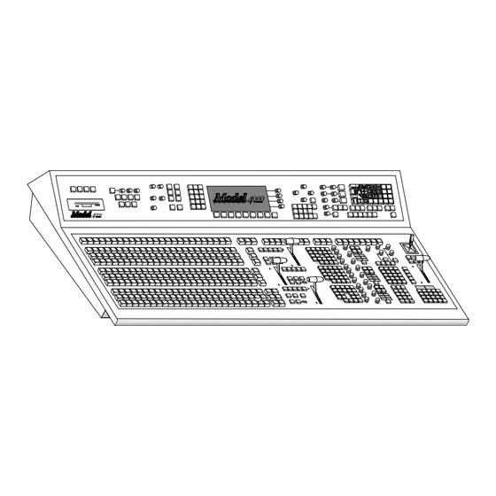
Tektronix Grass Valley 4000 Installation And Service (286 pages)
Digital Production Switcher
Brand:
Tektronix
| Category:
Switch
| Size: 2 MB
Table of Contents
Customer Support
2
Table of Contents
5
Important Safety Information
11
Regulatory Notices
11
Symbols and Their Meaning in this Manual
11
Danger
12
Warnings
12
Cautions
13
Power Cord Notices
13
North American Power Supply Cords
13
International Power Supply Cord
13
EMC Regulatory Notice
14
Section 1 - System Overview
15
Introduction
15
System Description
15
Available Options
19
Input Modules
19
Output Modules
19
Analog Outputs
19
Serial Outputs
20
Timed aux Outputs
21
Effects Send Matrix
21
Secondary Wipe Generators
22
Dual Chromatte Advanced Chroma Keyer
22
BORDERLINE Key Edge Generation
23
Tally Output
23
Look-Ahead Preview
23
Extender Modules
24
Frame Store Option
24
Power Supplies
25
Control Panel Power Supplies
25
Frame Power Supplies
25
Physical Description
26
Control Panel
26
Signal Processor Frame
26
System Specifications
28
Section 2 - Installation
35
Introduction
35
Unpacking
35
Pre-Installation Procedures
36
Items Required but Not Supplied
36
Physical Specifications and Installation Requirements
36
Environmental Characteristics
37
Power Requirements
37
Safety Requirements
37
Installation
39
Model 4000-2A/B Control Panel Installation
39
Model 4000-2A Cutout Dimensions
40
Model 4000-2B Cutout Dimensions
41
Inserting the 4000-2 Panel
42
Model 4000-2 Rear Cable Clearance
42
Model 4000-3 Control Panel Installation
43
Model 4000-3 Control Panel Console Dimensions
44
Inserting the Model 4000-3 Panel
47
Pushbutton Lens Chip Installation
48
Control Panel Option Installation
49
Model 4000-2 Redundant Control Panel Power Supply
49
Model 4000-3 Redundant Control Panel Power Supply
51
Model 4000-3 Input Readout Display Panel
53
Signal Processor Frame Installation
55
Signal Processor Frame Power Supply Installation
58
Frame Power Supply Assemblies
58
Model 4000-2A/B Only-Determining 110V or 220V AC Operation
59
Frame Fan Jumper Settings
62
Primary Frame Power Supply Installation
62
Redundant Frame Power Supplyinstallation
66
Frame Module Installation
71
Module Installation and Removal
71
Frame Module Locations
73
Optional Frame Module Installation
77
Input Modules
77
Serial Output Module Options
81
Chromatte Advanced Chroma Keyer
82
Effects Send Option
82
BORDERLINE Key Edge Generator Option
83
Secondary Wipe Pattern Generator Options
84
Look Ahead Preview Option
85
Tally Control Module Option
86
Timed aux Output Option
89
Remote aux Panel Option
90
Frame Store
93
Mask Draw Tablet Option
94
Installing UD and KT Series Tablets
94
Installing SD Series Tablet
95
Cable Connections
96
Control Panel Connections
97
Model 4000-2A/B Control Cable
98
Model 4000-3 Control Cable
98
Status Terminal Connections
100
Frame Signal Connections
101
Analog Reference Connection
101
Input Signal Connections (Video and Key)
101
Output Signal Connections
102
Frame Communications Panel Connections
110
Video Production Editor Connections
111
Connecting to a Krystal Digital Effects System
113
Connecting to Kaleidoscope
114
Connecting to a DPM-700
115
GPI Connections
117
Remote aux Connections
119
Tally Control Module Connections
123
Maintenance Terminal Connections
124
Power Connections to Control Panel and Frame
124
System Startup
126
Preliminary Steps
126
Power up
127
Primary and Redundant Power Supply Voltage Adjustments
128
System Configuration
130
System Timing
130
Autotiming
130
Procedure for Checking Input Timing
132
Analog Input Timing
133
Section 3 - Functional Description
139
Introduction
139
System Overview
140
Signal Processor Frame
140
Power Distribution
140
Control Panel
141
Signal Paths
141
System Overview
143
Signal Processor Frame
146
Frame Module Locations
146
Frame Module Descriptions
150
Input Modules
150
Output Modules
152
Serial Reentry Module (064822)
154
Crosspoint Module (064800)
155
DSK Crosspoint Module (Slot A3) (Buses 33-48)
155
M/E 2 Crosspoint Module (Slot A4) (Buses 17-32)
156
M/E 3 Crosspoint Module (Slot B2) (Buses 49-64)
156
M/E 1 Crosspoint Module (Slot A5) (Buses 1-16)
157
Keyer Carrier Module (064804)
157
M/E Key 1 Keyer Carrier Module
158
M/E Key 2 Keyer Carrier Module
159
DSK Key 1 Keyer Carrier Module
159
DSK Key 2 Keyer Carrier Module (Slot A15)
160
Keyer Mezzanine Board (064826)
161
M/E a Background Mezzanine Board
162
M/E B Background Mezzanine Board
162
M/E Key 1 Mezzanine Board
162
DSK Key 1 Mezzanine Board
163
DSK Program Background Mezzanine Board
163
M/E Key 2 Mezzanine Board
163
DSK B Background Mezzanine Board
164
DSK Key 2 Mezzanine Board
164
BORDERLINE Mezzanine (067909)
165
Mixer Interface Module (064813)
166
Effects Send Modules (064809)
171
Chroma Keyer Carrier Module (064807)
172
Chroma Key Mezzanine Board (064831)
172
M/E Chroma Keyer Module Set
172
MIX/Wipe Module (064803)
173
Wipe Mezzanine Board (064828)
173
Preview Mezzanine Board (064829)
174
M/E MIX/Wipe Module Set
174
DSK MIX/Wipe Module Set (Slot A16)
175
Sync Generator Module (064801) (Slot A9)
175
Frame Store Module (064814)
176
Timed aux Output Module (064852) (Slot D3)
177
Control Module Description
177
Control Processor 1 Module (064805) (Slot A1)
178
Communications Processor 2
180
Control Processor 2 Module (064806) (Slot A2)
180
M/E 2 Processor Mezzanine
180
M/E 3 Processor Mezzanine (4000-3 Only)
180
Communications I/O Module (064823) (Slot C3)
181
Expanded Communications Carrier Module (064824) (Slot C1)
181
GPI Module (064825) (Slot C4)
181
Tally Control Module (064808)
181
Control Panel Description
182
Control Panel Components
182
Model 4000-2A/B Control Panels
182
Model 4000-3 Control Panel
185
Control Panel Functional Operation
189
Model 4000-2A/B
189
Model 4000-3
191
Peripheral Utility Processor (Pup) Functional Operation
193
Power Supply Description
194
Control Panel
194
Signal Processing Frame
194
Remote aux Panel
195
Section 4 - Maintenance
197
Introduction
197
Servicing Precautions
198
Draining the Control Processor RAM
198
Powering down
199
Servicing Circuit Boards and Modules
200
Repairing Circuit Modules
200
Signal Processor Frame Servicing
201
Signal Processor Frame Module Precautions
201
Removing Modules from the Frame
202
Servicing Frame Power Supplies
205
Model 4000 Power Supply Configurations
205
Frame Power Supply Assemblies
205
Frame Power Supply Replacement
207
Replacement of Individual Power Supply Assemblies
210
Configurations
210
Procedures
210
Removal of Pioneer Multi-Output Supply
211
Replacement of Multi-Output Power Supply Assembly
211
Installation of Todd Multi-Output Supply
213
Mount Terminal Block
213
Install Assembly in Frame
214
Replacement of +5 Volt Power Supply Assembly
215
Removal of Pioneer +5 Volt Supply
215
Installation of Todd +5 Volt Supply
217
Frame Air Filter Cleaning
221
Frame Power Supply Air Filter Cleaning
223
Control Panel Servicing
224
Control Panel Servicing Precautions
224
Model 4000-3 Control Panel Board Locations
225
Model 4000-2A/B Control Panel Board Locations
227
Removing Control Panel Circuit Boards
228
Replacement of Control Panel Power Supplies
229
Model 4000-2 Control Panel Power Supplies
229
Replacement of Model 4000-3 Control Panel Power Supplies
232
Pushbutton Lamp Replacement
234
Section 5 - Troubleshooting and Diagnostics
235
Introduction
235
System 4000 Service Philosophy
236
Static Precautions
236
Module Extenders
236
Drawing and Parts Lists Manuals
237
Recommended Test Equipment
237
Required Reference Signals
237
Troubleshooting
238
Overall System Troubleshooting
238
Individual Module Troubleshooting
238
Troubleshooting
241
Module Troubleshooting Trees
250
Sync Generator Module
251
Preview Module
252
MIX/Wipe Module
253
Keyer Carrier Module
254
Tally Control Module
257
Mixer Interface Module
259
Analog Input Module
261
Analog Output Module
262
Serial Output Module
265
Serial Reentry Module
266
Control Panel Troubleshooting
270
Appendix A - Jetta Power Supply Information
271
Introduction
271
Power Supply Configurations
272
Installation Information
273
Initial Installation of the Model 4000-3
273
Replacement of Jeta +5 Volt Supply
274
Maintenance Information
278
Replacement of Individual Power Supply Units
278
Replacement of a Jeta +5 Volt Power Supply
278
Power Supply Voltage Adjustments
278
Adjusting Single Power Supply System
279
Adjusting Redundant Power Supply System
280
Wiring Diagrams
280
Index
281
Advertisement
Advertisement
Related Products
Tektronix GeoProbe G10
Tektronix GTS1063
Tektronix GTS1250
Tektronix 261
Tektronix 4000-3
Tektronix 7B92
Tektronix ECO 422
Tektronix Grass Valley 3000
Tektronix KEITHLEY 2750
Tektronix KEITHLEY 2750/E
Tektronix Categories
Test Equipment
Measuring Instruments
Amplifier
Portable Generator
Printer
More Tektronix Manuals
Login
Sign In
OR
Sign in with Facebook
Sign in with Google
Upload manual
Upload from disk
Upload from URL