Table of Contents
Advertisement
Quick Links
VoIP MultiPath/Gateway
This unit contains new hardware, which requires newer software. This software was installed
on the unit prior to leaving the factory.
If you must downgrade the software in this unit, please visit
rohs/
for a list of latest software patches that support this new hardware. Loading unsup-
ported software will render this unit inoperable and will require physical access to this unit for
recovery.
Tenor and Quintum are registered trademarks. PacketSaver, Quintum Technologies, Inc., Risk Free VoIP, VoIP
Made Easy, SelectNet, and SelectNet Technology are trademarks of Quintum Technologies, Inc.
VoIPon www.voipon.co.uk sales@voipon.co.uk Tel: +44 (0)1245 808195 Fax: +44 (0)1245 808299
Tenor AX
®
Switch
NEW HARDWARE SUPPORT
http://ae.quintum.com/support/
Advertisement
Table of Contents

Subscribe to Our Youtube Channel
Related Manuals for Quintum Tenor AX


Summary of Contents for Quintum Tenor AX
- Page 1 Tenor and Quintum are registered trademarks. PacketSaver, Quintum Technologies, Inc., Risk Free VoIP, VoIP Made Easy, SelectNet, and SelectNet Technology are trademarks of Quintum Technologies, Inc.
-
Page 2: Table Of Contents
What is the Tenor AX?........ - Page 3 Cables ..............2-6 50-Pin Cable .
- Page 4 If you need Additional Help ..........4-11 GLOSSARY INDEX Warranty/Approvals...
-
Page 5: About This Guide
bout this Guide P/N 480-0062-00-14 Preface-1 VoIPon www.voipon.co.uk sales@voipon.co.uk Tel: +44 (0)1245 808195 Fax: +44 (0)1245 808299... -
Page 6: What's Included
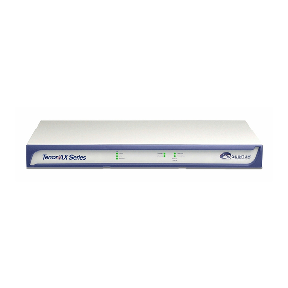
• Chapter 1: Overview. Includes a general overview of the product, including a description of the Tenor AX’s features and capabilities. • Chapter 2: Hardware Components. Hardware description, including the front and rear panels, as well as LEDs and required cables. -
Page 7: Typographical Conventions
About this Guide Typographical Conventions Product Guide Conventions Certain typographical conventions are used throughout this product guide. See below. • All commands you enter via keystrokes appear in bold (e.g., Press Enter or Press Ctrl-I). • All text commands you enter via Telnet session or command line typing appear in italics (e.g., type active). -
Page 8: Finding Help/More Information
Extensive configuration help is available via the Tenor Configuration Manager/Tenor Monitor User Guide or the Command Line Interface User Guide. Both documents are on the CDR ROM you received with the unit or you can download the latest documentation from www.quintum.com. Preface-4 P/N 480-0062-00-14... -
Page 9: Chapter 1: Overview
1: Overview This chapter gives you a general overview of the Tenor AX including feature descriptions and capa- bilities. Specifically, the following topics are covered: A description of Tenor AX Features Capabilities Call Paths Advanced Features/Capabilities P/N 480-0062-00-14 VoIPon www.voipon.co.uk sales@voipon.co.uk Tel: +44 (0)1245 808195 Fax: +44 (0)1245 808299... -
Page 10: What Is The Tenor Ax
Chapter 1: Overview What is the Tenor AX? The Tenor AX is a high-density VoiP (Voice over Internet Protocol) H.323/SIP switch that com- presses and packetizes voice, fax, and modem data and transmits it over the IP network. Designed for Enterprises and Service Providers, the Tenor AX gives large businesses with analog voice infra- structure an easy, cost-effective way to capitalize on the power of Voice over IP (VoIP). - Page 11 The MultiPath version’s architecture enables the Tenor AX to intelligently route calls between the FXS, FXO, and the VoIP network to achieve the best combination of cost and quality. The Tenor AX also routes calls over IP to reduce costs, and then transparently “hop off” to the PSTN, to reach off- net locations.
-
Page 12: Features
The Tenor AX’s specific features are explained below. Unique Design Tenor AX packs powerful VoIP features into one compact unit. The Tenor can be installed without upgrades to the existing voice or data network. You can install the unit anywhere, without affecting the network infrastructure you already have in place. -
Page 13: Capabilities
(A traditional tie trunk is a PBX-configured direct connection between two PBXs in separate locations. The tie trunk bypasses the PSTN network, which results in considerable savings.) Your PBX does not need any additional configuration. The Tenor AX treats all trunks the same with- out compromising voice quality. -
Page 14: Snmp Support
Call Detail Recording Through the Call Detail Record (CDR) feature, the Tenor AX generates a call record at the comple- tion of each call, typically for accounting purposes. A CDR is a string of data that contains call information such as call date and time, call duration, calling party, and called party. -
Page 15: Dynamic Call Routing
Tenor AX will first identify the call origination site—Line/FXO, Phone/FXS, or IP routing group — and then route the call according to the parameters you have configured in the routing database. -
Page 16: Tenor Ax Call Paths
VoIP call, a Line Circuit, or trunk typically for connection to a termination device on the user’s premises such as a PBX. The routing decision made by the Tenor AX is based upon your configuration and the dialed number. See... - Page 17 Chapter 1: Overview IP Network Calls. Calls coming from the IP network data can be routed to the Line/FXO or Phone/ FXS interfaces. The Tenor will route calls based upon the dialed number. If the number is config- ured as a local phone number, the call will be sent to a Phone/FXS circuit for termination, otherwise the call is considered a “Hop-Off call”...
-
Page 18: Tenor Axt Trunking Voip Gateway (Axt800, Axt1600, Axt2400, Axt4800) Configuration
Chapter 1: Overview Tenor AXT Trunking VoIP Gateway (AXT800, AXT1600, AXT2400, AXT4800) Configu- ration The Tenor AXT Trunking VoIP Gateway Configuration is used for trunk side PSTN (Line/FXO port) to VoIP connections; calls coming from the Line/FXO interface (i.e.PSTN) may be switched to the data network as a VoIP call. - Page 19 Chapter 1: Overview Tenor AXE Enterprise VoIP Gateway (AXE800, AXE1600, AXE2400) Configuration The Tenor AXE Enterprise VoIP Gateway is mainly intended for applications interfacing between the PBX and the VoIP network, but it also includes two FXO ports for autoswitching PSTN back-up and 911 service provision.
-
Page 20: Advanced Features/Capabilities
For example, you may want to configure 911 as a “bypass number”, which means that all 911 calls coming into Tenor AX from the line circuit will be routed directly to a Trunk circuit presumably con- nected to a PSTN. Bypass calls are never routed over IP. -
Page 21: H.323 Gatekeeper Services
Tenor AX supports those hop-off PBX calls where the destination Tenor AX is programmed to route the call to the PSTN. The destination Tenor AX unit is configured with the phone numbers to be “supported” for this feature. - Page 22 In addition, if you are using more than one Tenor unit, you can configure one of the border elements for that zone. The Tenor AX unit can use two border elements: primary and secondary. These work together as one entity to provide redundancy and fault tolerance; there are no hierarchal differences.
-
Page 23: Sip User Agent
Chapter 1: Overview network access and protects the integrity of the network using Admissions Request (ARQ), Admis- sions Confirmation (ACF) and Admissions Reject (ARJ) messages. SIP User Agent SIP (Session Initiation Protocol) is a signaling protocol used to establish a session on an IP network for voice control and management;... -
Page 24: Chapter 2: Hardware Components
hapter 2: Hardware Components This chapter tells you what is contained in your hardware package. A description of each component is also included. Specifically, the following topics are covered: Hardware Description Cables Specifications P/N 480-0062-00-14 VoIPon www.voipon.co.uk sales@voipon.co.uk Tel: +44 (0)1245 808195 Fax: +44 (0)1245 808299... -
Page 25: Front Panel Connections And Reset Options
Chapter 2: Hardware Components Hardware Description The Tenor AX is a stackable device which provides Phone/FXS and Line/FXO connections as well as connections to the Ethernet LAN and a PC. The unit’s front panel includes LEDs; the back panel includes connection jacks, a diagnostics option, a reset button, and an on/off power switch. - Page 26 Chapter 2: Hardware Components Label LED Color Description 100Mb Green On: The advertised link rate is 100Mb if the link is not connected, or the actual link rate is 100b if the link is connected. Off: The advertised link rate is 10Mb if the link is not connected, or the actual link rate is 10Mb if the link is connected.
-
Page 27: Back Panel
Chapter 2: Hardware Components Back Panel Console Port Power Switch Phone/FXS port Reset Line/FXO port Power LAN port Diag Receptacle For AXT4800 only, For AXT4800 only, this is labeled this is labeled LINE/FXO(1-24) LINE/FXO(25-48) • Phone/FXS port. Provides a 50 Pin Telco connector which supports up to 24 Phone/FXS con- nections for connecting to the PBX, Keyphone or phones. - Page 28 Chapter 2: Hardware Components Pin # Signal Definition Color RSVD Reserved Blue RSVD Reserved White w/blue RX - Receive Data Green RSVD Reserved White w/Brown RSVD Reserved Brown • Console port. This RS-232 connector is used for connection to a PC’s serial port via DB-9 serial cable at 38400 BPS 8N1, without flow control.
-
Page 29: Cables
Chapter 2: Hardware Components Cables The cables listed in Table 2-4 are required to connect a Tenor AX to various interfaces. Contact Quintum for ordering information, if necessary. Table 2-4 Cables Supported Cable Usage 50-Pin Telco Connector Connection to FXO/Line... -
Page 30: 50-Pin Cable
Chapter 2: Hardware Components 50-Pin Cable The 50-pin Telco shielded cable connection pinouts and wire colors are given in this section to help you identify the proper specifications for connection to the FXO/Line and FXS/Phone ports. For the 50-pin Telco cable, terminate only one end with a Female, AMP 50-pin Telco Connector with 180 degree entry. - Page 31 Chapter 2: Hardware Components Figure 2-4 50-Pin Cable Connector Specifications Connector Wire Color Wire Band DSO #'s Pin #'s Tip wire Ring wire Pin # Color w/ Color Blue / White 1 & 26 Slot 1 line 1 Orange / White 2 &...
- Page 32 Figure 2-5 RJ-45 Pin Order Side View Top View An RJ-45 (10/100BaseT) straight through cable is used to connect Tenor AX to an Ethernet LAN. Cable pinouts are listed in Figure 2-6. Color specifications are applicable to the RJ-45 cable pro- vided.
-
Page 33: Db-9 Serial Rs-232 Cable
DB-9 Serial RS-232 Cable The Serial RS-232 9-pin cable with a DB-9 male connector (with RS-232 interface) is used to con- nect the Tenor AX to your PC’s asynchronous serial port. The pin order for DB-9 male and female connectors are shown in... -
Page 34: Specifications
Chapter 2: Hardware Components Specifications Voice/Fax Call Routing: FXO/FXS/IP Voice Algorithms: G.723.1A (5.3, 6.3 Kbps), G.726 (16, 24, 32, 40 Kbps), G.729A, G711 Fax Support: Group III at 2.4, 4.8, 7.2, 9.6, 12, 14.4 Kbps Automatic Call Detection:Voice/Modem/Fax PSTN/PBX Connections Interface: Analog, FXO Interface (PSTN side), FXS Interface (PBX side) Connector:... -
Page 35: Installation
3: Installation/Basic Troubleshooting This chapter gives you installation instructions, as well as how to position the Tenor AX successfully within your network. In addition, basic troubleshooting techniques are included. Specifically, the following topics are covered: Installation Connect to Phone/FXS... -
Page 36: Pre-Installation Guidelines
• Ensure there is clearance between the fan intake/exhaust on the side of the unit to avoid airflow being blocked. Inspect Package Contents Before you install the hardware, ensure the following components are included in our shipment: • Tenor AX and Mounting Hardware • 1 AC Power Cable • 1 DB-9 RS-232 Serial Cable • RJ-45 Cable •... -
Page 37: Rack Install
Chapter 3: Installation/Basic Troubleshooting Rack Install Locate the Tenor AX unit within the same area as your PBX, Ethernet hub, switch, router, and/or PSTN patch panel. The unit is intended to be installed in a 19” rack. Mounting brackets are attached to the chassis; the rack is not included with your system. Included with the unit are the screws below. - Page 38 Chapter 3: Installation/Basic Troubleshooting Attach the unit to the wall as follows: 1. Determine the wall area to mount the unit. With chalk or a soft pencil, mark the install area according to Figure 3-1. NOTE: Ensure the unit is level. Figure 3-1 Wall Mounting Dimensions 3/16”...
- Page 39 Chapter 3: Installation/Basic Troubleshooting Preparing the Single-ended or Double-ended Telco Cable Depending on your order, you will have received either a double-ended or a single-ended 50-pin Telco cable. Follow these steps for preparing and installing the cables. Single-ended 50-pin Cable If you have ordered a single-ended shielded 50-pin Telco cable, you must prepare it for use with your specific application.
-
Page 40: Connect To Phone/Fxs Interface
Since there are many different PBX devices, key systems, fax machines and phones you can connect to the Tenor AX, the instructions which follow explain the general procedure for connecting an external device to the Phone/FXS port through the 50-pin Telco connector. Use the phone/FXS ports for on-premise wiring only. - Page 41 Chapter 3: Installation/Basic Troubleshooting 2. Insert the other end of the 50-pin Telco cable into the appropriate port on the PBX, key system, or another device that connects interfaces, such as a break out box. For the PBX connection, see your PBX documentation port requirements for connection specifics.
-
Page 42: Connect To Line/Fxo Interface
Chapter 3: Installation/Basic Troubleshooting Connect to Line/FXO Interface For the AXT4800 product only, the Line/FXO interface is labeled “LINE/FXO (25-48)”. NOTE: To connect to the Line/FXO port, you must first connect the analog phone lines to another piece of equipment that houses your telephone lines running to the PSTN, such as the patch panel, punch down block or wire wrap blocks. -
Page 43: Connect To Ethernet Lan
Connect to Ethernet LAN You can use these instructions for general connection purposes only. The Ethernet hub/switch manu- facturer’s documentation should provide specific instructions for connection to another device, such as the Tenor AX. Figure 3-6 Connect to Ethernet Hub/Switch RJ-45 Cable... -
Page 44: Connect To Pc Console
Chapter 3: Installation/Basic Troubleshooting Connect to PC Console You will need to connect the Tenor AX to your workstation’s serial port via RS-232 connection. (This connection will be used when you assign an IP address to the unit.) For the instructions below, it is assumed you are connecting to a Windows PC. -
Page 45: Power Up The System
Chapter 3: Installation/Basic Troubleshooting Power up the System Once you have all cables connected properly, you are ready to turn the system on as follows: 1. Plug in the power cord to an AC outlet. 2. Locate the on/off switch on the back of the unit and click the switch to On. The unit will power up and the LEDs will flash and turn off;... -
Page 46: Assign Ip Address
Assign IP address Before you can configure the Tenor AX, you need to assign a valid IP address. An IP address is a 32 bit (up to 12 numeric characters) address used to identify each network device in the TCP/IP net- work. -
Page 47: Change Ip Address
2. Click on Start> Programs> Accessories> Communications>HyperTerminal> Run. The Connec- tion Description window will be displayed. 3. Enter a connection name (i.e., name for each unit such as Tenor AX New Jersey). 4. Click Ok. 5. Choose the serial port on your PC from the Connect Using drop down list box (i.e., Direct to Com 1). - Page 48 9. From the Stop bits drop down list box, choose 1. 10.From the Flow control drop down list box, choose None. 11. Press the Tenor AX power switch to On. After the bootup sequence, the login prompt will appear. 12.Enter a login name. The default login name is admin.
- Page 49 Once the IP information is set, you are ready to configure the unit. See the Tenor Configuration Manager/Tenor Monitor User’s Guide and Command Line Interface (CLI) User Guide for specifics. Both documents are on the CDR ROM you received with the unit or you can download the latest documentation from www.quintum.com. P/N 480-0062-00-14 3-15...
-
Page 50: Getting Started With Configuration/Making The First Call
When configuring a firewall, set up a DMZ (this makes the firewall act as a switch so that all incoming IP traffic for the firewall’s WAN IP will be routed directly to the Tenor AX). If you are using a cable modem with No firewall, specific configuration options are also included. - Page 51 7. At the VoIP Configuration> H323 Signaling Group screen, set the Primary Gatekeeper IP (i.e., 208.226.140.40 for Quintum’s test unit) Click on Confirm/OK. Allows the unit to get the information it needs to route your phone call to a specific IP address.
-
Page 52: Load Software Upgrade
Chapter 3: Installation/Basic Troubleshooting 12.Pick up the phone and hear dial tone. Dial 7324609000. The call should route to Quintum’s test unit and you should hear a recorded message. dial 7324609000 (ten-digits), your unit (the Gateway) consults the Gate- When you keeper's table of phone number to IP translations (the Gatekeeper is an application or function inside the test Gateway at 12.176.187.080), and sends the appropriate data to... -
Page 53: Common Symptoms/Problems
Network issues may cause a number of problems. Contact the Central Office to perform test procedures. Communication with Command Line Inter- The IP address of the Tenor AX unit may be incorrect. face (CLI) cannot be established using Tel- Check Ethernet cable. - Page 54 Description/Solution Communication between computer’s COM Verify DB-9 cable is firmly placed in the unit’s console port port and Tenor AX serial port cannot be and your PC’s serial port. established. Verify Terminal port settings at 38400 BPS 8N1 No Flow Control.
-
Page 55: Monitor Leds
hapter 4: Advanced Topic: Diagnostics/ Maintenance This chapter explains the advanced topics for monitoring alarms and performing maintenance/diag- nostic procedures. Monitor LEDs Monitor Alarms Verify Unit Provisioning Perform Maintenance Procedures Finding Additional Help P/N 480-0062-00-14 VoIPon www.voipon.co.uk sales@voipon.co.uk Tel: +44 (0)1245 808195 Fax: +44 (0)1245 808299... -
Page 56: How To Read Alarms
Tenor Monitor. Alarms are brief text messages that appear on your workstation when the Tenor AX unit encounters a problem, such as a failed interface, disconnected call, etc. There are two ways to view alarms for the Tenor AX unit: through the Command Line Interface (CLI) or through Tenor Monitor. - Page 57 Chapter 4: Advanced Topic: Diagnostics/Maintenance Field Definition Valid Entry Severity Level or alarm severity. 1 = Critical (complete system is affected). 2 = Major (major problem is detected). 3 = Minor (minor problem is detected). 4 = Info (Information about a minor problem).
-
Page 58: Valid Alarms
Critical Critical Software Error A software error has occurred that affects the operability of the complete system. Critical Tenor AX Chassis reset The unit has reset. Critical Configuration Data Missing Configuration via CLI is missing. Check the configura- tion data and add the necessary information. - Page 59 Chapter 4: Advanced Topic: Diagnostics/Maintenance Severity Alarm Description (appears as Definition part of severity (text appears in desc field) field) Major Major Software Error A software error has occurred that affects system signal- ing, interfaces, or other major operation. Major File Missing in the File Server This alarm will be reported to the system when a partic- ular voice prompt file is not found in the IVR Prompt...
-
Page 60: Display All Alarms
Chapter 4: Advanced Topic: Diagnostics/Maintenance Severity Alarm Description (appears as Definition part of severity (text appears in desc field) field) Informational Glare occurred An incoming and outgoing call went through at the same time, and the remote end call did not back off, but the situation was corrected. -
Page 61: Display Active Alarms
Chapter 4: Advanced Topic: Diagnostics/Maintenance Display Active Alarms You are able to display all active alarms as follows: 1. Through CLI, access the Monitor prompt. 2. Type alarm a. The active alarms will be listed. See section Valid Alarms for field definitions. If you enter alarm without a command following it, both active alarms and the alarm history will be displayed. -
Page 62: Verify Unit Provisioning
Chapter 4: Advanced Topic: Diagnostics/Maintenance Verify Unit Provisioning An error with Tenor AX‘s provisioning may cause a number of problems. It may be a simple error, such as an incorrect IP address or telephone number. See the Command Line Interface (CLI) guide or the Tenor Configuration Manager/Tenor Monitor User’s Guide for provisioning information. -
Page 63: Maintenance Procedures
The Reset system feature enables you to reset the system, including hardware and software. You can reset the system through the unit’s Back Panel or through the Command Line Interface (CLI). Back Panel. Use a blunt, thin object to press in the Reset button, located on Tenor AX’s front panel. The system will reset. -
Page 64: Change Password
Chapter 4: Advanced Topic: Diagnostics/Maintenance 3. Type reset. You will be asked if you are sure you want to set the unit back to factory defaults. 4. Type yes to confirm (type no to cancel the restore). Change Password For security purposes, you may want to change the password. You can change the password via Command Line Interface (CLI) as follows: 1. - Page 65 Chapter 4: Advanced Topic: Diagnostics/Maintenance If you need Additional Help If you suspect the problem to be on the network end, contact your Central Office to verify proper operation. After completing all troubleshooting/maintenance procedures and reviewing the Common Symp- toms/Problems section, you can contact the Customer Service Department at the following: 4-11 P/N 480-0062-00-14 VoIPon www.voipon.co.uk sales@voipon.co.uk Tel: +44 (0)1245 808195 Fax: +44 (0)1245 808299...
- Page 66 Alarm. A brief message that appears on your screen when the Tenor AX encounters a problem (i.e., failed Ethernet port. A port on the Tenor AX which provides interface). Alarms can be viewed through CLI (see RJ-45 jacks for connection to a 10/100 Ethernet LAN Command Line Interface) or a Telnet connection.
- Page 67 LAN in New York, a LAN in Tokyo, and a LAN in Los Angeles. When these sites connect together over RJ-45. A CAT 5 cable used to connect the Tenor AX to the data network or the public network, it is consid- an Ethernet.
- Page 68 INDEX 2-10 DB-9 factory defaults Numerics restore 50-pin cable Features prepare double ended 1-12 advanced prepare single ended easy connect GUI and network management IVR/RADIUS About this guide PacketSaver Alarms SelectNet display via CLI system monitoring field definitions unique design list of 3-16 First Call...
- Page 69 IP Network Calls Tenor AX description LEDs product types monitor What is Tenor AX? Troubleshoot common problems Maintenance unit provisioning 4-10 change date/time typographical conventions 4-10 change password reset system 1-12 restore factory defaults UPDP NATAccess Virtual Tie Trunk...
- Page 70 Customers are responsible for shipping and insurance charges to return the defective product. Quintum shall pay for shipping and insurance charges for the part being sent to the customer.
- Page 71 PLEASE NOTE: All shipments require an authorized RMA number. If the Customer does not comply with this procedure as set out above, Quintum reserves the right to charge Customer for the cost of the replace- ment Product and/or freight (including duties and taxes) from Quintum regardless of the reason for the return. Quintum also reserves the right to invoice the Customer for a replacement Product at the same time as the replacement is cross-shipped.
-
Page 72: Documentation Notice
Documentation Notice Information in this document is subject to change without notice and does not represent a commitment on the part of Quintum Technologies, Inc. The recipient of this document has a personal, non-exclusive and non-transferable license to use the information contained within solely with Quintum Tech- nologies, Inc. -
Page 73: Fcc Warnings
FCC WARNINGS This equipment has been tested and found to comply with the limits for Class A digital device, pursuant to Part 15 of the FCC Rules. These limits are designed to provide reasonable protection against harmful interfer- ence in a residential installation. This equipment generates, uses and can radiate radio frequency energy and, if not installed and used in accordance with the instructions, may cause harmful interference to radio commu- nications. - Page 74 Support insert for repair information and the warranty section of this Product Manual for warranty informa- tion. In the event of device malfunction, all repairs should be performed by Quintum Technologies, Inc. or an authorized agent. It is the responsibility of users requiring service to report the need for service to our com- pany or to one of our authorized agents.
- Page 75 Canadian Notice The Industry Canada label identifies certified equipment. This certification means that the equipment meets certain telecommunications network protective, operation, and safety requirements. The Department does not guarantee the equipment will operate to the users' satisfaction. Before installing this equipment, users should ensure that it is permissible to be connected to the facilities of the local Telecommunications Company.
- Page 76 Agency Approvals EMI/EMC Standards FCC Part 15 Class A ICES-003 EN55022:98 EN55024:98 EN61000-3-2 :95 EN61000-3-3:95 AS/NZS 3548:1995 Safety Standards UL60950-1 CSA C22.2 No.60950-1 EN60950:99 TS001:1970 Telecom Standards FCC Part 68 CS-03 AS/NZ 3260:1997 AS/ACIFS002:2001 AS/ACIF S003:2001 European Directives EMC Directive, 89/336/EEC Low Voltage Directive, 73/23/EEC R&TTE Directive, 99/5/EC VoIPon www.voipon.co.uk sales@voipon.co.uk Tel: +44 (0)1245 808195 Fax: +44 (0)1245 808299...
- Page 77 RoHS Compliance EU Directive on Restriction of Hazardous Substances (RoHS) All Quintum products with Part Numbers in the series 501-1XXX- XX are fully compliant with the requirements set forth in the Euro- pean Union (EU) Directive 2002/95/EC on the Restriction of use of certain Hazardous Substances in electrical and electronic equipment (RoHS).
-
Page 78: Declaration Of Conformity
Taiwan, R.O.C Analog VoIP Gateway Type of Equipment: Model Number: Tenor AX Series We, the undersigned, hereby declare that the equipment specified above conforms to the above Directive(s) and standard(s) as of this date. Place: Eatontown, NJ, USA Date: 8/29/2005 Karl V.
Need help?
Do you have a question about the Tenor AX and is the answer not in the manual?
Questions and answers