Table of Contents
Advertisement
This unit contains new hardware, which requires newer software. This software was installed
on the unit prior to leaving the factory.
If you must downgrade the software in this unit, please visit
rohs/
for a list of latest software patches that support this new hardware. Loading unsup-
ported software will render this unit inoperable and will require physical access to this unit
for recovery.
The current release of the Tenor Monitor does not support the Tenor AF
NOTE:
Series.
Tenor and Quintum are registered trademarks. Quintum Technologies, Inc., PacketSaver, Risk Free VoIP,
The Perfect Fit, are trademarks of Quintum Technologies, Inc.
Tenor AF
VoIP Switch
NEW HARDWARE SUPPORT
®
http://ae.quintum.com/support/
Advertisement
Table of Contents

Related Manuals for Quintum Tenor AF


Summary of Contents for Quintum Tenor AF
-
Page 1: New Hardware Support
Loading unsup- ported software will render this unit inoperable and will require physical access to this unit for recovery. The current release of the Tenor Monitor does not support the Tenor AF NOTE: Series. -
Page 2: Table Of Contents
What is the Tenor AF?........ - Page 3 Online/Offline Mode - AFE400/AFE600 only ....... . 2-6 Cables..............2-7 RJ-11 Cables .
- Page 4 Quintum Limited Warranty ........
-
Page 5: About This Guide
bout this Guide P/N 480-0084-00-12 Preface-1 VoIPon www.voipon.co.uk sales@voipon.co.uk Tel: +44 (0)1245 808195 Fax: +44 (0)1245 808299... -
Page 6: What's Included
• Chapter 2: Hardware Components. Hardware description, including the front and rear panels, as well as LEDs and required cables. • Chapter 3: Installation. Describes how to install the Tenor AF unit, including how to connect and power up the system. -
Page 7: Typographical Conventions
About this Guide Typographical Conventions Product Guide Conventions Certain typographical conventions are used throughout this product guide. See below. • All commands you enter via keystrokes appear in bold (e.g., Press Enter or Press Ctrl-I). • All text commands you enter via Telnet session or command line typing appear in italics (e.g., type active). -
Page 8: Finding Help
Extensive configuration help is available from the Tenor Configuration Manager User Guide or the Command Line Interface User Guide. Both documents are on the CDR ROM you received with unit, or you can download the latest documentation from http://www.quintum.com/support. P/N 480-0084-00-12 Preface-4 VoIPon www.voipon.co.uk sales@voipon.co.uk Tel: +44 (0)1245 808195 Fax: +44 (0)1245 808299... -
Page 9: Chapter 1: Overview
1: Overview This chapter gives you a general overview of the Tenor AF, including feature descriptions and capa- bilities. Specifically, the following topics are covered: A description of Tenor AF Features Capabilities Call Paths Advanced Features/Capabilities P/N 480-0084-00-12 VoIPon www.voipon.co.uk sales@voipon.co.uk Tel: +44 (0)1245 808195 Fax: +44 (0)1245 808299... -
Page 10: What Is The Tenor Af
The Tenor AF is a VoIP (Voice over Internet Protocol) H.323/SIP switch that digitizes voice, fax, and modem data, and transmits it over the IP network. Designed as a SOHO product, the Tenor AF gives small to medium sized businesses with analog voice infrastructure an easy, cost-effective way to capitalize on the power of Voice over IP (VoIP). - Page 11 Chapter 1: Overview Table 1-1 Tenor AF Configuration Types Series Configuration FXS Ports FXO Ports VoIP Ports AFG200 AFG VoIP Switch AFG400 AFG800 AFT200 AFT VoIP Switch AFT400 AFT800 AFM200 AFM MultiPath Switch AFM400 AFE400 AFE Enterprise VoIP Gateway AFE600...
-
Page 12: Features
The Tenor AF’s specific features are explained below. Unique Design The Tenor AF packs powerful VoIP features into one compact unit. The Tenor can be installed with- out upgrades to the existing voice or data network. You can install the unit in a home or office envi- ronment, without affecting the network infrastructure you already have in place. -
Page 13: Capabilities
Tenor, are instead routed via VoIP to the remote Tenor. SNMP Support The Tenor AF supports Simple Network Management Protocol (SNMP), the standard protocol used to exchange network information between different types of networks. -
Page 14: Call Detail Recording
Handbook available on the CD you received with the unit, or at http://www.quintum.com/support. IVR/RADIUS Support Interactive Voice Response (IVR) is a feature of the Tenor AF that enables you to offer services to your customers, such as Pre-paid calling cards and Post-paid accounts. -
Page 15: Dynamic Call Routing
Chapter 1: Overview Dynamic Call Routing The Tenor AF’s intelligent call routing capabilities are state-of-the-art. The unit automatically detects and supports three call types: voice, fax, and modem. The Tenor will first identify the call origination site—Line/FXO or Phone/FXS—and then route the call according to the parameters you have configured in the routing database. -
Page 16: Tenor Af Call Paths
Chapter 1: Overview Tenor AF Call Paths Tenor VoIP Switch (AFG200, AFG400, AFG800) Configuration The Tenor VoIP Switch configuration is used for Phone/FXS ports connecting to the VoIP Network. The number of VoIP ports is equal to the number of FXS ports. Calls coming from the Phone/FXS interface (e.g., PBX) may be switched to the data network as a VoIP call. -
Page 17: Tenor Voip Switch (Aft200, Aft400, Aft800) Configuration
Chapter 1: Overview Tenor VoIP Switch (AFT200, AFT400, AFT800) Configuration The Tenor VoIP Switch configuration is used for trunk side PSTN (Line/FXO port) to VoIP connec- tions. Calls coming from the Line/FXO interface (i.e., PSTN) may be switched to the data network as a VoIP call. - Page 18 VoIP call, a Line Circuit, or trunk typically for connection to a termination device on the user’s premises such as a PBX. The routing decision made by the Tenor AF is based upon your configuration and the dialed number. See...
-
Page 19: Tenor Voip Switch (Tenor Afe400, Afe600)
Chapter 1: Overview Tenor VoIP Switch (Tenor AFE400, AFE600) The Tenor AFE Enterprise VoIP Gateway is mainly intended for applications interfacing between the PBX and the VoIP network, but it also includes two FXO ports for autoswitching PSTN back-up and 911 service provisioning. The number of VoIP ports is equal to the number of FXS ports. Calls can be routed in any direction between any of the ports. -
Page 20: Advanced Features/Capabilities
For example, you may want to configure 911 as a “bypass number”, which means that all 911 calls coming into Tenor AF from a telephone or PBX will be routed directly to a Trunk circuit pre- sumably connected to a PSTN. Bypass calls are never routed over IP. -
Page 21: H.323 Gatekeeper Services
Tenor AF supports those hop-off PBX calls where the destination Tenor AF is programmed to route the call to the PSTN. The destination Tenor AF unit is configured with the phone numbers to be “supported” for this feature. -
Page 22: Sip User Agent
In addition, if you are using more than one Tenor unit, you can configure one of the border elements for that zone. The Tenor AF unit can use two border elements: primary and secondary. These work together to provide redundancy and fault tolerance. - Page 23 Chapter 1: Overview able to gateway calls to and from the IP network, and Customer Premise Equipment (CPE) such as phones, PBX's, and FAX machines, or the Public Switched Telephone Network (PSTN). The Tenor SIP User Agent will work in conjunction with an external SIP proxy or redirect server to route and connect calls over SIP based networks.
-
Page 24: Chapter 2: Hardware Components
hapter 2: Hardware Components This chapter tells you what is contained in your hardware package. A description of each component is also included. Specifically, the following topics are covered: Hardware Description Cables Specifications P/N 480-0084-00-12 VoIPon www.voipon.co.uk sales@voipon.co.uk Tel: +44 (0)1245 808195 Fax: +44 (0)1245 808299... -
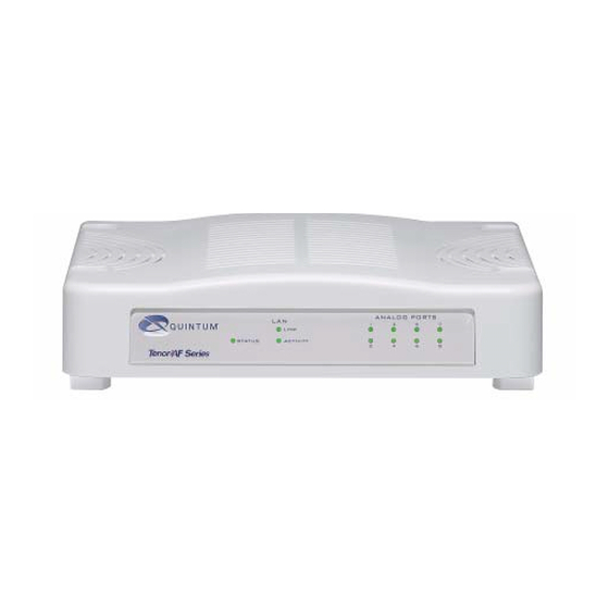
Page 25: Front Panel Leds
Chapter 2: Hardware Components Hardware Description The Tenor AF is a stackable device which provides Phone/FXS and Line/FXO connections as well as connections to the Ethernet LAN and a PC. The unit’s front panel includes LEDs; the back panel includes connection jacks, a diagnostics but- ton, and a power adapter jack. -
Page 26: Back Panel
1, 2 3, 4...8 Green On: Indicates the Line/FXO or Phone/FXS port is in use. Off: Indicates the Line/FXO or Phone/FXS port is not in use. Back Panel Figure 2-2 Tenor AF Back Panel DIAG CONSOLE LAN port port Power Adapter jack... - Page 27 Chapter 2: Hardware Components Table 2-2 Serial RS232 DB-9 Connector Pinouts Pin # Function Description Data Terminal Ready Transmit Data Receive Data Carrier Detect Signal Ground N.C. No Connect N.C. No Connect N.C. No Connect N.C. No Connect • LAN port. 10/100 Base-T Ethernet port. This port provides an RJ-45 jack for an individual connection to a 10/100 Ethernet LAN switch or hub via RJ-45 cable;...
- Page 28 Chapter 2: Hardware Components • Port Label (Phone/FXS or Line/FXO ports). For Phone/FXS, provides an RJ-11 jack for connection to a PBX, Keyphone or analog phone. For Line/FXO, enables connection to another piece of equipment that houses your telephone lines running to the PSTN, such as the patch panel.
-
Page 29: Online/Offline Mode - Afe400/Afe600 Only
If the FXS has a matching FXO port, the FXS will have online/offline capability. If the FXS goes offline, it will automatically connect to the corresponding port shown in 2-7. For detailed Figure information about online/offline capability, see the Command Reference Guide available at http:// www.quintum.com/support. Figure 2-7 Online/Offline Capability AFE400 Ports AFE600 Ports P/N 480-0084-00-12 VoIPon www.voipon.co.uk sales@voipon.co.uk Tel: +44 (0)1245 808195 Fax: +44 (0)1245 808299... -
Page 30: Rj-11 Cables
RJ-11 Cables An RJ-11 to RJ-11 cable is used to connect the Tenor AF to an FXO or FXS external device. The RJ- 11 cable connector pinouts are given in this section to help you identify the proper connector to accommodate your specific networking requirements. -
Page 31: Ethernet Cable (10/100)
Coloring. The pin order is shown in Figure 2-10. An RJ-45 (10/100 Base-T) straight through shielded cable is used to connect Tenor AF to an Ether- net LAN. Cable pinouts are listed in 2-6. Color specifications are applicable to the RJ-45 cable Table provided. -
Page 32: Db-9 Serial Rs-232 Cable
DB-9 Serial RS-232 Cable The Serial RS-232 9-pin cable with a DB-9 male connector (with RS-232 interface) is used to con- nect the Tenor AF to your PC’s asynchronous serial port. The pin order for DB-9 male and female connectors are shown in... -
Page 33: Specifications
Chapter 2: Hardware Components Specifications Voice/Fax Call Routing: FXO/FXS Coding: A-law , mu-law Voice Algorithms: G.723.1A (5.3, 6.3 Kbps), G.726 (16, 24, 32, 40 Kbps), G.729A, G711 Fax Support: Group III at 2.4, 4.8, 7.2, 9.6, 12, 14.4 Kbps Automatic Call Detection:Voice/Modem/Fax PSTN/PBX Connections Interface: Analog, FXO Interface (PSTN side), FXS Interface (PBX side) -
Page 34: Chapter 3: Installation
3: Installation This chapter gives you installation instructions, as well as how to position the Tenor AF successfully within your network. Specifically, the following topics are covered: Installation Power up the System Login Without PC’s COM Port/Obtain IP Address from Ethernet Login Through PC’s COM Port... -
Page 35: Pre-Installation Guidelines
Chapter 3: Installation Installation Before you begin the actual installation, review the pre-installation guidelines which follow and inspect the package contents. Pre-Installation Guidelines • Do not make connections from the Tenor to your public phone lines during any kind of electri- cal storm. - Page 36 Chapter 3: Installation The Tenor AF has two wall-mount slots, which are located on the bottom of the unit. Attach the unit to the wall as follows: 1. Determine the wall area to mount the unit. With chalk or a soft pencil, mark the install area...
- Page 37 Chapter 3: Installation Figure 3-2 Engage Wall Mount Slots over Screws in Wall 4.6” (116.84 mm) Engage the wall mount slot over the screws inserted in the wall. Unit Bottom P/N 480-0084-00-12 VoIPon www.voipon.co.uk sales@voipon.co.uk Tel: +44 (0)1245 808195 Fax: +44 (0)1245 808299...
-
Page 38: Connect To Phone/Fxs Interface
Since there are many different PBX devices, key systems, fax machines and phones you can connect to the Tenor AF, the instructions which follow explain the general procedure for connecting an RJ- 11 cable (included in your package) between the Phone/FXS port and an external device. Use the phone/FXS ports for on-premise wiring only. -
Page 39: Connect To Line/Fxo Interface
Chapter 3: Installation Connect to Line/FXO Interface To connect to the Line/FXO port, you can first connect the analog phone lines to another piece of equipment that houses your telephone lines running to the PSTN, such as the patch panel. If you are unsure of the installation procedures, contact the network administrator or review the documentation you received with the PBX. -
Page 40: Connect To Ethernet Lan
Connect to Ethernet LAN You can use these instructions for general connection purposes only. The Ethernet hub/switch manu- facturer’s documentation should provide specific instructions for connection to another device, such as the Tenor AF. Figure 3-5 Connect to Ethernet Hub/Switch RJ-45... -
Page 41: Connect To Pc Console (If Required, See Note)
Static IP address. You will need to connect the Tenor AF to your workstation’s serial port through the RS-232 connec- tion (This connection will be used when you assign an IP address to the unit). For the following instructions, it is assumed you are connecting to a Windows PC. -
Page 42: Power Up The System
COM port. Through the LAN port on the Tenor AF, you can connect to a port on a router that is capable of pro- viding DHCP. You can then look at the active lease table of the firewall to get an IP address. If there is no DHCP service available when you turn the unit on, the Tenor gets an IP address of 169.254.xx.xx, where xx and yy are the last two bytes of the serial number (in decimal), which... -
Page 43: Login Through The Pc's Com Port (If Required, See Note)
Description window is displayed. 2. Enter a connection name (i.e., name for the unit such as Tenor AF NJ). Click OK. 3. Choose the serial port on your PC from the Connect Using drop down list box (i.e., Direct to Com 1). - Page 44 Chapter 3: Installation • Flow control: None 5. Click OK. 6. Power up the unit via System. A connection to the Tenor will establish. Information Power up the about the unit will scroll on the screen, followed by a message, "WITHIN 4 SECONDS, PRESS 'r' FOR FACTORY DEFAULTS or 'i' to SET STATIC IP".
-
Page 45: Chapter 4: Diagnostics/Maintenance
hapter 4: Diagnostics/Maintenance This chapter explains the advanced topics for diagnosing problems with the unit, viewing system alarms, and performing maintenance procedures, such as upgrading the software. Common Symptoms/Problems Monitor LEDs Monitor Alarms Verify Unit Provisioning Perform Maintenance Find Additional Help P/N 480-0084-00-12 VoIPon www.voipon.co.uk sales@voipon.co.uk Tel: +44 (0)1245 808195 Fax: +44 (0)1245 808299... - Page 46 Network issues may cause a number of problems. Contact the Central Office to perform test procedures. Verify that the unit is online. Communication with Command Line The IP address of the Tenor AF unit may be incorrect. Interface (CLI) cannot be established using Telnet. Check Ethernet Cable.
- Page 47 Verify RJ-45 cable is firmly installed in the LAN port. switch cannot be established. Check MDI/MDIX configuration. Verify the mode setting on the Tenor AF matches the mode setting on the hub/switch. Check duplex setting on the switch in which they were connected and the speed of 10 Mb/ sec or 100 Mb/sec.
-
Page 48: Monitor Leds
AC power source to ensure power is being supplied to the unit. Monitor Alarms Alarms are brief text messages that appear on your workstation when the Tenor AF unit encounters a problem, such as a failed interface, disconnected call, etc. Alarms help you identify where a specific problem is occurring with the Tenor AF unit. - Page 49 Chapter 4: Diagnostics/Maintenance Field Definition Valid Entry Type (displays only if you The type of alarm generated. ALR = Alarm. Exceptional generate an Alarm History) condition which may be a crit- ical, major, or minor condition which impacts the ability to make calls.
- Page 50 Chapter 4: Diagnostics/Maintenance Field Definition Valid Entry Date/Time Date/time the event occurred Day of week: name of day. Month: Jan, Feb, March, etc. Day of month: 1 or 2 digits. Time: 6 digits (hour minutes seconds based on a 24-hour clock).
-
Page 51: Valid Alarms
Critical Critical Software Error A software error has occurred that affects the oper- ability of the complete system. Critical Tenor AF Chassis reset The chassis has reset. Critical Configuration Data Missing Configuration is missing. Check the configuration data and add the necessary information. - Page 52 Chapter 4: Diagnostics/Maintenance Severity Alarm Description (appears as Definition (text appears in desc field) part of severity field) Critical RADIUS Server Not Responding Appears when none of the configured RADIUS servers respond. This alarm is cleared when any of the RADIUS servers responds or the RADIUS server is disabled via CLI.
-
Page 53: Display All Alarms
Chapter 4: Diagnostics/Maintenance Severity Alarm Description (appears as Definition (text appears in desc field) part of severity field) Minor Log RADIUS server error Displayed when the RADIUS server fails to send required data or the data sent by the RADIUS server has improper values. -
Page 54: Display Active Alarms
Chapter 4: Diagnostics/Maintenance Display Active Alarms You are able to display all active alarms as follows: 1. Through CLI, access the Monitor prompt. 2. Type alarm a. The active alarms will be listed. See section for field defini- How to Read Alarms tions. -
Page 55: Verify Unit Provisioning
Chapter 4: Diagnostics/Maintenance Verify Unit Provisioning An error with provisioning the Tenor AF may cause a number of problems. It may be a simple error, such as an incorrect IP address or telephone number. See the Command Line Interface (CLI) guide or the Tenor Configuration Manager Product Guide for configuration information. -
Page 56: Reset System
Description window is displayed. 2. Enter a connection name (i.e., name for the unit such as Tenor AF NJ). Click OK. 3. Choose the serial port on your PC from the Connect Using drop down list box (i.e., Direct to COM 1). -
Page 57: Change Password
Chapter 4: Diagnostics/Maintenance Change Password For security purposes, you may want to change the password. You can change the password through the Command Line Interface (CLI) as follows: 1. Access the CLI through a Telnet session. See the Command Line Interface (CLI) guide for more information. -
Page 58: If You Need Additional Help
If you suspect the problem to be on the network end, contact your Central Office to verify proper operation. After completing all troubleshooting/maintenance procedures and reviewing the Common Symp- toms/Problems section, you can contact the Technical Support Department at the following: Quintum Technologies, Inc. 71 James Way Eatontown, NJ 07724 For domestic calls: (877) 435-7553 For international calls: (732) 460-9399 email: service-ticket@quintum.com... -
Page 59: Glossary
10 automatically switch the call to the PSTN. to 100 Mbps. Ethernet port. A port on the Tenor AF which pro- Border Element. Provides access into or out of an vides RJ-45 jacks for connection to a 10/100 administrative domain. - Page 60 Switching facility. Zone. A group of endpoints (e.g, gateways, termi- nals, etc.) in one corporate site. RJ-11. A cable used to connect the Tenor AF to an FXO or FXS interface. RADIUS. When using IVR, the RADIUS (Remote Authentication Dial-In User Service) is used for authenticating and authorizing user access to the VoIP network.
-
Page 61: Index
IVR/RADIUS INDEX PacketSaver system monitoring unique design Front panel ports 1-8 About this guide reset Alarms FXO Calls 1-10 active 4-10 FXS Calls display display via CLI field definitions H.323 1-13 history 4-10 border element 1-13 list of call registration 1-13 monitor call services... - Page 62 2-10 physical 2-10 PSTN/PBX 2-10 voice/fax 2-10 Static Routes 1-12 System AC power up reset 4-12 Tenor AF Tenor AS description What is Tenor AS? Troubleshoot unit provisioning 4-11 verify unit provisioning 4-11 typographical conventions UPDP 1-12 Wall mount 480-0084-00-12 Index-2 VoIPon www.voipon.co.uk sales@voipon.co.uk Tel: +44 (0)1245 808195 Fax: +44 (0)1245 808299...
-
Page 63: Warranty/Approvals
Customers are responsible for shipping and insurance charges to return the defective product. Quintum shall pay for shipping and insurance charges for the part being sent to the customer. - Page 64 If the Customer does not comply with this procedure as set out above, Qui ntum reserves the right to charge Customer for the cos t of the replace- ment Product and/or freight (including duties and taxes) from Quintum regardless of the reason for the return. Quintum also reserves the right to invoice the Customer for a r eplacement Product at the same time as the replacement is cross-shipped.
-
Page 65: Documentation Notice
Documentation Notice Information in this document is subject to change without notice and does not represent a commitment on the part of Quintum Technologies, Inc. The recipient of this document has a personal, non-exclusive and non-transferable license to use the information contained within solely with Quintum Tech- nologies, Inc. -
Page 66: Agency Approvals
Agency Approvals EMI/EMC Standards FCC Part 15 Class B ICES-003 EN55022:98 Class B EN55024:98 EN61000-3-2:95 EN61000-3-3:95 AS/NZS 3548:1995 Safety Standards UL60950-1 CSA C22.2 No.60950-1 EN60950:99 TS001:1970 Telecom Standards FCC Part 68 CS-03 AS/NZ 3260:1997 AS/ACIFS002:2001 AS/ACIF S003:2001 European Directives EMC Directive, 89/336/EEC Low Voltage Directive, 73/23/EEC R&TTE Directive, 99/5/EC VoIPon www.voipon.co.uk sales@voipon.co.uk Tel: +44 (0)1245 808195 Fax: +44 (0)1245 808299... -
Page 67: Fcc Warnings
FCC WARNINGS This equipment has been tested and found to comply with the limits for Class B digital device, pursuant to Part 15 of the FCC Rules. These limits are designed to provide reasonable protection against harmful interference in a residential installation. This equipment generates, uses and can radiate radio frequency energy, and, if not installed and used in accordance with the instructions, may cause harmful interference to radio communica- tions. - Page 68 In the event of device malfunction, all repairs should be performed by Quintum Technologies, Inc. or an authorized agent. It is the responsibility of users requiring service to report the need for service to Quintum Technologies or to one of our authorized agents. In the event service is required, refer to the Technical Support insert for information.
-
Page 69: Canadian Notice
Canadian Notice The Industry Canada label identifies certified equipment. This certification means that the equipment meets certain telecommunications network protective, operation, and safety requirements. The Department does not guarantee the equipment will operate to the users' satisfaction. Before installing this equipment, users should ensure that it is permissible to be connected to the facilities of the local Telecommunications Company. - Page 70 RoHS Compliance EU Directive on Restriction of Hazardous Substances (RoHS) All Quintum products with Part Numbers in the series 501-1XXX-XX are fully compliant with the requirements set forth in the European Union (EU) Directive 2002/95/EC on the Restriction of use of certain Hazardous Sub- stances in electrical and electronic equipment (RoHS).
Need help?
Do you have a question about the Tenor AF and is the answer not in the manual?
Questions and answers