
Related Manuals for EverFocus EMS200S


Summary of Contents for EverFocus EMS200S
- Page 1 User Manual...
-
Page 2: User Manual
All rights reserved. No part of the contents of this manual may be reproduced or transmitted in any form or by any means without written permission from the Everfocus Electronics Corporation. Release Date: September, 2012 QuickTime is a registered trademark of Apple Computer, Inc. -
Page 3: Safety Precautions
SAFETY PRECAUTIONS Ventilation Slots: Do not block the ventilation openings or slots on the cover. Limits for Temperature, Humidity and Power: Do not operate the device beyond its specified temperature, humidity or power source ratings. Do not use the device in environments with very high temperature or humidity. - Page 4 This Product is RoHS compliant. WEEE Your EverFocus product is designed and manufactured with high quality materials and components which can be recycled and reused. This symbol means that electrical and electronic equipment, at their end-of-life, should be disposed of separately from your household waste. Please, dispose of this equipment at your local community waste collection/recycling centre.
-
Page 5: Table Of Contents
TABLE OF CONTENTS PRODUCT OVERVIEW ..........................1 FEATURES ............................1 PACKAGE CONTENTS ........................2 SPECIFICATIONS ..........................3 FRONT PANEL ............................. 5 REAR PANEL ............................6 CONNECTION DIAGRAM ........................7 REAR PANEL CONNECTORS / D-S ..................8 ABLE INSTALLATION PROCEDURE ......................10 VIDEO I/O REQUIREMENTS ...................... - Page 6 5.1.3 Camera Settings – Alarm ............................30 RECORD ............................. 31 ALARM/GPS ............................32 5.3.1 Alarm – Alarm Settings ............................32 5.3.2 Alarm – Event Settings ............................33 5.3.3 Alarm – Video Loss .............................35 5.3.4 Alarm – G Sensor Settings ..........................36 5.3.5 Alarm – GPS (Speed)............................37 5.3.6 Alarm –...
- Page 7 7.2.2 Enabling ActiveX Controls ...........................73 REMOTE LIVE VIEW ......................... 76 REMOTE PLAYBACK ........................78 EVERFOCUS DDNS SETUP ........................79 LINKSYS & D-LINK PORT FORWARDING ................... 80 TYPICAL LINKSYS PORT FORWARDING ..................80 TYPICAL D-LINK PORT FORWARDING ..................82 TROUBLESHOOTING ..........................84 APPENDIX A: TIMING OF ALARM MODES ....................
-
Page 8: Product Overview
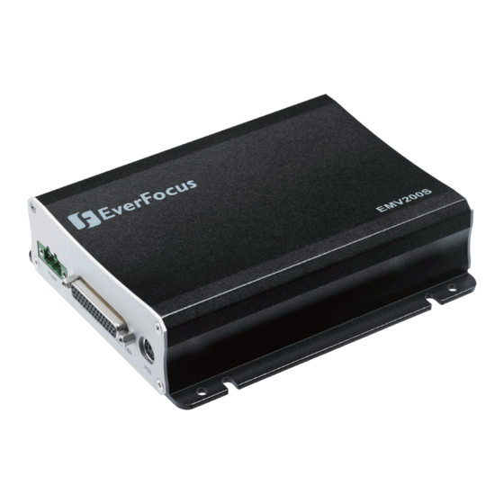
1 PRODUCT OVERVIEW Full-feature video surveillance in the palm of your hand: The EverFocus EMV200S/EMV400S digital video recorder features a built-in 3-axis G-sensor, an external plug- in GPS module for location tracking, and H.264 compression for efficient recording and fast network transmission of recorded data. -
Page 9: Package Contents
Plug-and-play recording on a shockproof SD card that comes with a security cover (only the 32GB SD cards from Transcend and Sandisk have been tested) The user can simply take out the full SD card and insert an empty one, or export video through two ... -
Page 10: Specifications
1.3 SPECIFICATIONS EMV200S - 2CH Mobile DVR EMV400S - 4CH Mobile DVR Video Format NTSC/PAL (auto-detected by system) Operating System Embedded Linux with special small-monitor-friendly GUI Video Input 2 channels (via a vibration-resistant, screw-locked 4 channels (via a vibration-resistant, screw- D-Sub harness adapter with BNC-F interface locked D-Sub harness adapter with BNC-F connectors) - Page 11 Playback Rate NTSC : D1 = 60fps NTSC : D1 = 120fps PAL : D1 = 50fps PAL : D1 = 100fps Playback Search Time/Date and Event search Video Loss Detection Event Alarms SD card error, SD card temperature, SD card full, SD card missing, power loss, network loss, GPS loss, GPS speed, GPS fencing Email Alerts Multiple email notifications in response to selectable alarms and events...
-
Page 12: Front Panel
1.4 FRONT PANEL Your primary interaction with your new DVR will be through the Front Panel buttons/ports and their corresponding buttons on the included IR Remote Control. Take a moment to learn where these features are as the remainder of the manual will refer to them often. -
Page 13: Rear Panel
1.5 REAR PANEL During initial setup you will be connecting your DVR to multiple input and output devices. This is done through the rear panel. Rear Panel: Power Input D-Sub Harness Adapter Port PS2 Port Power Input: Connect to a 10VDC~32VDC power source. D-Sub Harness: Plug the supplied D-Sub harness adapter in here. -
Page 14: Connection Diagram
1.6 CONNECTION DIAGRAM Note: This usage scenario shows possible usage of the DVR. All peripheral devices must be purchased separately. See page 2 for package contents. -
Page 15: Rear Panel Connectors / D-Sub Cable
1.7 REAR PANEL CONNECTORS / D-Sub Cable Rear Panel Connectors Power Video / Audio / Alarm / RS232 / DB9 Video / Audio PIN No. Description Vedio_in1 Vedio_in2 Vedio_in3 Vedio_in4 Vedio_out Audio_in1 Audio_in2 Audio_in3 Audio_in4 Audio_out PIN No. Description Cable Tab VIN1 VIN2 VIN3... - Page 16 D-Sub Cable EMV200s D-Sub Connector RS-232 2 Alarm In / 1 Alarm Out Audio In (1 ~ 2) / Audio Out Video In (1 ~ 2) / Video Out EMV400s D-Sub Connector RS-232 4 Alarm In / 1 Alarm Out Video In (1 ~ 4) / Video Out Audio In (1 ~ 4) / Audio Out...
-
Page 17: Installation Procedure
1.8 INSTALLATION PROCEDURE Unpack Everything • Make sure you have everything you need before you begin the installation. Equipment Required • The following tools may help you to complete the installation: •Drill •Screwdrivers •Wire cutters Choosing the Installation Location • Choose a location that: •Provides convenient access (and leaves enough room) for installing or removing the hard drive •Allows air to flow around the DVR’s fan vents. - Page 18 Possible Installation Locations Inside a Truck • Glove box (inside or underneath) Driver’s seat (between the seat and the back panel) or underneath the Passenger seat The diagram below shows the wiring on the wiring harness that connects to the electrical system. •...
- Page 19 The diagram below shows the wiring on the wiring harness that connects to the electrical system. • Note: 1. If the car is without an ignition key, please connect the IGN (yellow) wire directly or via a switch to the vehicle battery.
- Page 20 Installing the Camera(s) and Monitor • The DVR is typically connected to one camera that is installed inside the car. Other cameras can also be installed in different locations in the car (for example, use a waterproof camera on the outside of the vehicle). A typical monitor’s power supply would usually connect to the car’s cigarette-plug adapter.
-
Page 21: Video I/O Requirements
1.9 VIDEO I/O REQUIREMENTS Cameras and CCTV monitors attached to this DVR must use copper-based 75 Ohm video cable (e.g. RG-59, RG- 6, or RG-11) with BNC connectors (preferably male, or female via a female-female adapter). Due to the possibility of impedance mismatch and undesired loss/reflections, 50 Ohm coax cable (e.g. RG-58) and 75 ohm foil shield antenna cable and other types of coaxial cable are not compatible. -
Page 22: Alarm Contacts Installation
1.11 ALARM CONTACTS INSTALLATION The 2/4 alarm inputs can be used to trigger recordings or to adjust recording rates. These inputs can also trigger alarms that cause the feed of the connected camera to be displayed on the surveillance monitor, or they can trigger buzzers, e-mail alerts and network alarms. -
Page 23: Network Connection
1.13 NETWORK CONNECTION This section only describes physical connections to an Ethernet network. This step must be completed before the DVR can connect to the network. There are two basic types of connection: 1.13.1 Direct PC Connection through Crossover Network Cable Point-to-point connection of the DVR to a PC requires a crossover (crossed) network cable. -
Page 24: Network Connection Through Patch Cable
1.13.2 Network Connection through Patch Cable The connection to an existing network requires a normal patch cable (straight-through). The illustration shows the connection to a network switch or router. Connection via a network: Pinout of straight-through patch cable (for a network connection): 1.14 STARTUP PROCEDURE Once you have completed the basic wiring connections, you are ready to turn on the DVR. -
Page 25: Using The Mouse
Chapter 2 USING THE MOUSE The EMV200S/EMV400S supports two ways of controlling the DVR. It can be controlled with a mouse or with the handheld IR remote control. (For IR remote control, please refer to Appendix C: Remote Control.) This chapter will cover basic operations via mouse control. 2.1 SELECTING A CAMERA CHANNEL 1. -
Page 26: Field Input Options
2.3 FIELD INPUT OPTIONS The following are examples of different input options available in the OSD configuration menu. Text box: Click on any text box and an on-screen keyboard will appear*. (More details about the on-screen keyboard follow below.) Dropdown box: Click on the down arrow to see all options, then click on an option to select it. Check box: Click on a box to enable it (checked) or disable it (unchecked). -
Page 27: Controls And Login
Chapter 3 CONTROLS AND LOGIN 3.1 MOUSE OR I.R. REMOTE This DVR can be configured through menu options in its on-screen Playback bar and Configuration menu. To access these menu options, connect the video output cable on the supplied D-Sub harness adapter (marked “VOUT”) to the Video In cable of a monitor, then use a connected mouse or the remote control to configure the menu settings. -
Page 28: Playback Menu
Chapter 4 PLAYBACK MENU 1. To bring up the root menu, right-click with the USB mouse to bring up the root menu. In this section we will look at the Playback menu options. The Root Menu 2. Click on the “Playback” icon “ ”... -
Page 29: Search
Fast Forward Click to start Fast Forward. Click repeatedly to cycle through the FF speeds. Click the Play/Stop button to stop. Search Click to search recorded data by Date/Time, Event, G Sensor event or GPS event. Please see section 3.4 for more details about the search function. -
Page 30: G Sensor Search
Click the button to enter the G Sensor Search menu. Click the button to enter the GPS Speed Search menu. Click the button to enter the Event Search menu. Click the button to go back to live view. 4.1.2 G Sensor Search After clicking the Search icon on the Playback bar, the Time Search page will open. - Page 31 data within the selected time period where GPS events of the selected type occurred (periods when the vehicle exceeded the selected speed). The GPS Speed Search menu From: Select the date and time of recording from which you want the DVR to start searching. To: Select the date and time of recording at which you want the DVR to stop searching.
-
Page 32: Event Search
From: Select the date and time of recording from which you want the DVR to start searching. To: Select the date and time of recording at which you want the DVR to stop searching. GPS Border Type: Select either a circle or a rectangle. Search Mode: Select if the search should look for events Inside or Outside the configured border. -
Page 33: Archive (To Usb Device)
Click on the button to start searching. The search results will be shown as a list of events. The Event List menu shows the results of the Event Search Prev Page: Go to previous page Next Page: Go to next page Play: Play back selected item Delete: Delete selected item Click the... - Page 34 Start Date/Time: Select the date/time of recording that will be the beginning of the recorded period which you want to archive. End Date/Time: Select the date/time of recording that will be the end of the recorded period which you want to archive.
-
Page 35: Configuration Menu
Chapter 5 CONFIGURATION MENU This chapter will walk you through the DVR’s Configuration menu items and show you how to set the DVR for your specific application. 1. Right-click to bring up the Root menu. The Root Menu 2. Click on the “Configuration” icon ( ) to enter the Configuration menu. -
Page 36: Camera
5.1 CAMERA Clicking on the camera icon opens the Camera Settings – Normal menu. This menu is used to configure individual camera recording settings. Clicking on the Camera icon opens the Camera Settings-Normal menu 5.1.1 Camera Settings – Normal No.: Camera’s channel number. Speed: Frame rate in frames (images) per second (FPS) for continuous recording. -
Page 37: Camera Settings - Video Adjust
5.1.2 Camera Settings – Video Adjust The Camera Settings - Video Adjust menu Camera: Select the channel number of the camera you wish to adjust. The “Title” field will display the given name of the selected camera. Brightness: Adjusts how bright/dark the picture appears. If details appear to be lost in the shadows or darker regions, try increasing the Brightness. -
Page 38: Record
Speed: This is the maximum desired frame rate in frames per second (FPS) for alarm-event recording; if more than one camera requires simultaneous event recording, the total for all cameras cannot exceed the maximum available FPS for the DVR at the corresponding resolution setting, and the available FPS may be divided across the cameras responding to an event. -
Page 39: Alarm/Gps
Auto Erase Video: The hard drive will automatically erase video after it has been on the hard drive for the selected number of days. To use the maximum available hard drive space, choose “OFF”. (See the Record Overwrite section and notes above.) This feature is useful if local rules and regulations require recorded video to be discarded after a specific number of days, or to limit the retention of older recorded video to clear space in anticipation of event recording. -
Page 40: Alarm - Event Settings
Network Alarm: Check this box to send out a network alarm to a client PC when motion occurs. (This feature requires CMS software, including EverFocus’ PowerCon or PowerVideo Plus, and setting up Alarm Server in Network Setup menu; see Section 4.7.6 Alarm Server for more information.) Click button to return to the previous level of menu. - Page 41 Network Alarm: Check box to send out a network alarm to client PC. (requires CMS software, including EverFocus’ PowerCon or PowerVideo Plus, and setting up Alarm Server in Network Setup menu) Alarm Output: This will transmit a signal through the alarm output. It can be set to either “NONE” (not active), “1”(output 1 is active).
-
Page 42: Alarm - Video Loss
Network Alarm: Check this box to send out a network alarm to a client PC when video loss occurs. (This feature requires CMS software, including EverFocus’ PowerCon or PowerVideo Plus, and setting up Alarm Server in Network Setup menu; see Section 4.7.6 Alarm Server for more information.) Apply To: This button can be used to copy the video loss settings to other cameras. -
Page 43: Alarm - G Sensor Settings
Network Setting/Email setup screen. Network Alarm: Check this box to send out a network alarm to client PC. (Requires CMS software, including EverFocus’ PowerCon or PowerVideo Plus, and setting up Alarm Server in Network Setup menu.) Click... -
Page 44: Alarm - Gps (Speed)
5.3.5 Alarm – GPS (Speed) Figure 5-21 Alarm – GPS Speed Speed Unit: If the speed is being recorded from the GPS receiver, the desired speed measurement units (kph or mph) must be selected. Selecting MPH lets the DVR display the GPS speed in miles per hour, and vice versa. GPS Speed: Select whether to record the vehicle speed (ON) or not (OFF). -
Page 45: Alarm - Gps Fencing
Network Setting/Email setup screen. Network Alarm: Check box to send out a network alarm to client PC. (requires CMS software, including EverFocus’ PowerCon or PowerVideo Plus, and setting up Alarm Server in Network Setup menu) 5.3.7 Alarm –... -
Page 46: Date / Time
Upper Left Latitude.: Set Upper Left Latitude if border type is rectangle. Upper Left Longitude: Set Upper Left Longitude if border type is rectangle. Lower Right Latitude: Set Lower Right Latitude if border type is rectangle. Lower Right Longitude: Set Lower Right Longitude if border type is rectangle. 5.4 DATE / TIME When in the Root menu, click the Configuration icon, then the Date/Time icon. -
Page 47: Date/Time - Daylight Saving Settings
b) Click on “START” -> “RUN” -> type “command” and press “OK”. c) In the DOS Prompt, type “ping pool.ntp.org” to find out the IP address of an NTP Server. If selecting “GPS”, you will be able to do the following setting: Update Interval: The frequency that the system automatically updates the time via the NTP server. -
Page 48: Display
5.5 DISPLAY In the Configuration menu, click the Display icon to open the Display – Title Settings screen shown below. This menu will walk you through the Main Monitor’s On-Screen Display (OSD) and Main Monitor Sequence setup. Click the buttons at the bottom to open other Display setup menus. Display –... -
Page 49: Display - Layout
Playback Date/Time: Check the box to display playback date/time. Playback Status: Check the box to display playback status. Event Status: Check the box to display event status. SD Card Status: Check the box to display the SD Card status. GPS Status: Check the box to display GPS status. Network Loss: Select Disabled, LAN, or 3G. -
Page 50: Display - Main Monitor Sequence
5.5.4 Display – Main Monitor Sequence Click the button to set up Sequence parameters. Step: Sequence order. For reference. Camera: Select which camera appears in the current step. Dwell (sec): Set the dwell time for each step. Sequence dwell time can be set from 0 to 99 seconds. Sequence repeats continuously from steps 1 through 20 until interrupted. -
Page 51: Lan Settings
5.6.1 LAN Settings Click the LAN icon to open the LAN setup options. NOTE: Since every Network Configuration is different, please check with your Network Administrator or ISP to see if your DVR should use specific IP addresses and/or port numbers. Network Type: Static IP: User can set a fixed IP for network connection. - Page 52 b. If using a Fixed IP (recommended), you will need to input the information manually. In order for DDNS to work, you must enter valid data, compatible with your network, for all four of the network setting fields: IP address, subnet mask, default gateway and the DNS Address (depending on your network hardware and configuration this may be the IP address of your router/gateway, or it may be the actual IP address of the local DNS server).
-
Page 53: Mobile Connection Settings
5.6.2 Mobile Connection Settings GPRS Service: Select “On” to enable GPRS service (CHAP or PAP). Select “Off” to disable GPRS function. APN (Access Point Name): By local ISP setting. Phone Number: Input the phone number to dial for mobile connection. User Name: Input the user name required for mobile connection. -
Page 54: Ddns Settings
DVR Name: Input the desired name for the DVR Register / Update: Click the button to submit and register the name to the Everfocus server. The DDNS name you choose must be unique; that is, it must not already be in use. Please go to the website http://everfocusddns.com and check that the name you wish to use is available. -
Page 55: Alarm Server Settings
Example: http://hostname.everfocusddns.com It is not necessary to append the HTTP port number to the DDNS name. The EverFocus DDNS server not only keeps track of your DVR’s IP address, it keeps track of the ports too! www.dyndns.org... -
Page 56: Meta Server Settings
5.6.6 Meta Server Settings Data Type: Choose between GPS Data and G-Sensor Data. Send GPS Data to Remote Server: Check to enable this function. Keep Connection Alive: Check to enable this function. Server IP: Enter the IP address of the server. Protocol: Choose the server’s transmission protocol (TCP or UDP). -
Page 57: System
5.7 SYSTEM From the Configuration root menu, click on the System icon to open the System setup options. This menu is for setting up the general system parameters for the DVR. Click the User icon to open the User configuration menu. 5.7.1 User User Menu is where you can add or delete different login IDs on the system as well as set access levels. - Page 58 Edit Click “Edit” button to make changes to an existing user account. Press “Save” button to save changes or “Cancel” to exit without making changes. System-User-Edit There are three system access levels – Admin, User, and Guest. The following tables show the configuration rights of each level.
-
Page 59: I/O Control
Date/Time Display Network System Information NOTE: User-level users can change only their own passwords and the passwords of Guest-level users; and they can only add, delete or edit usernames for lower levels. 5.7.2 I/O Control This menu is used to define the settings for controlling the DVR through RS232, and for DVR control of attached PTZ cameras. - Page 60 System – I/O Control – GPS Baud Rate: The speed used to transmit instructions or information through the GPS on the DVR. Choose from the following speeds: 1200, 2400, 4800, 9600, 19200, 38400, 57600, 115200 BPS. Data Bit: The number of data bits used in a data packet or word. This can be set to 8 or 7. Stop Bit: This field is to set the number of stop bits indicating the end of a data packet.
-
Page 61: Sd Card
5.7.3 SD Card This screen is used to view the DVR’s storage settings and status. No values in this screen can be changed by the operator. System – SD Card NOTE: You may be prompted to format the SD card when first inserting the SD card to the SD card slot on the front-panel of the mobile DVR. - Page 62 To remove the SD Card, please see the following steps: 1. Click “Unmount” button, the message of “Unmount SD Card?” appears. 2. Click “Yes”, and the process of removing the SD card begins. 3. After the process is done, the status of the SD card will display N/A. And then you may remove the SD card.
-
Page 63: Log
5.7.4 This screen is used to choose, display and/or export log entries. From: Date: Select starting date of log to be displayed. Time: Select starting time of log to be displayed. Date: Select end date of log to be displayed. Time: Select end time of log to be displayed. -
Page 64: Settings (Login & Language)
Click the View Log button on the Log menu to see the Log List. Prev Page: Go to the previous page of the log. Next Page: Go to the next page of the log. Close: Close the window. Click button to return to the previous level of menu. 5.7.5 Settings (Login &... -
Page 65: Service (Firmware Upgrade, Defaults, Etc.)
5.7.6 Service (Firmware Upgrade, Defaults, etc.) The System – Service menu Firmware Current Firmware Version: Displays the current version. Upgrade from USB: Press “Upgrade” to upgrade the firmware. NOTE: To perform a Firmware Upgrade, you will need to connect a USB storage device with the desired firmware on it. -
Page 66: Information
5.7.7 Information This menu displays important (read only) system information. Information System Version: Displays firmware version number. Model: Displays DVR model number. System: (NTSC or PAL) Displays current video format – based on the video format of Camera 1 during boot up. Status SD Card: Displays whether an SD Card is inserted or not. -
Page 67: Networking Overview
Chapter 6 NETWORKING OVERVIEW This chapter will give you a basic instruction on how to set up the DVR for network connection. It is highly recommended that you have a working knowledge of what a network is and how it works. This will be helpful in completing the networking process. -
Page 68: Pre-Installation
There are many types of high speed Internet available. The most common ones are T1, Cable, and DSL (in order of speed). This DVR is not compatible with a dial-up connection. Note: EverFocus suggests having a minimum upload speed of 256Kbps. This can be addressed by your Internet Service Provider. -
Page 69: What Is Your Network Setup
This makes it much simpler to host a website, email server, or other type of server connection. Everfocus suggests using a static IP address. If this is not available, you will need to use a dynamic IP address. This is explained below. -
Page 70: Simple One-To-One Connection
2. Once you have a cross-over cable plug one end into the LAN port on the back of the DVR and the other into the network card on the back of the computer. 3. Log into the EverFocus DVR menu and go to the Network Setting Menu. 4. You must use the Static IP option for this type of connection. - Page 71 7. Follow the instructions below to assign a fixed IP address in Windows 2000/XP.
- Page 72 8. Click on the option that says “Use the following IP address” 9. Assign an IP address of 192.168.1.2, a Subnet Mask of 255.255.255.0, and a Default Gateway of 192.168.1.1, then click OK. 10. Restart both the computer and the DVR. 11.
-
Page 73: Direct High-Speed Modem Connection
2. Once you have a straight through cable plug one end into the LAN port on the back of the recorder and the other into the high speed modem. 3. Log into the EverFocus DVR menu and go to the Network Setting Menu. 4. Input the Static IP address, the Subnet Mask, and the Gateway that you obtained from the internet... -
Page 74: Router Or Lan Connection
Note: If you have a dynamic IP address, you can set the DVR to DHCP to automatically detect the network settings. Therefore, it can use a dynamic IP address. 5. Exit from the DVR’s Menu to save the settings. 6. - Page 75 2. Once you have a straight through cable plug one end into the LAN port on the back of the recorder and the other into the router. 3. Log into the EverFocus DVR menu and go to the Network Setting Menu. 4. To let the router automatically assign an address: ...
- Page 76 Take the values for Subnet Mask and Default Gateway and input them into the DVR; these values should be exactly the same in both devices. However, you should change the last number of the IP address. For example, if the IP address of the computer is 192.168.2.101, the DVR’s IP address should be 192.168.002.050.
-
Page 77: Remote Operation From Browser
Chapter 7 REMOTE OPERATION FROM BROWSER 7.1 CONNECTING TO THE EMV200S/EMV400S To access the DVR from a computer, open an Internet Explorer window and in the address bar type: “Local connection” + “:” + “IP port used” Example: “http:// (IP address from the DVR’s Network Menu)” + “:” + “2468” Example: http://192.168.1.163:2468 “Internet connection”... -
Page 78: Browser Security Setting
7.2 BROWSER SECURITY SETTING 7.2.1 Installing ActiveX controls When you first connect to the DVR’s IP address, you should see a screen like the one below. If you do not see a yellow bar like the one the arrow is pointing at, your security settings may be too high. If so, go to Section 7.2.2 (“Enabling ActiveX Controls”). - Page 79 Install the MSXML file when prompted to do so. Now, you will be able to see the remote live page.
-
Page 80: Enabling Activex Controls
7.2.2 Enabling ActiveX Controls Note: This section is only necessary if you DO NOT see the yellow ActiveX bar at the top of your browser screen when you first connect to the DVR. At the top of the Internet Explorer Window, click on Tools, then select Internet Options. Click the Security tab at the top of the window, then choose Custom Level near the bottom. - Page 81 In the Security Settings window, scroll to “ActiveX controls and plug-ins” Set the controls as follows: “Enable”: Allow previously unused ActiveX controls to run without prompt (Internet Explorer 7 only) Allow scriptlets (IE7 only) Automatic prompting for ActiveX controls ...
- Page 82 Install the ePlusDVR.cab file when prompted to do so. Once the file finishes installing, you will return to the same login page as before. Type in the user name and password and click Login to view the cameras. Default user name: admin – Default password: 11111111.
-
Page 83: Remote Live View
7.3 REMOTE LIVE VIEW 1. Click on a camera number on the left side of the display to switch that camera to full screen. Click on “4UP” to display 4 screens. 2. You can click the “Mic” button to transfer audio to DVR from client side if there is a microphone attached to the PC and an amplifier and speaker attached to the DVR. - Page 84 Network Setup System Setup Information Setup Copy Menu Search Menu 5. In the main page, you will see live images in a 4-screen display.
-
Page 85: Remote Playback
7.4 REMOTE PLAYBACK To playback the video, click the “Search” button. Select from “Time Search”, “G Sensor Search”, “GPS Search” or “Event Search”. For more details about Search setting, please refer to “4.1 Search Setting”. Back: returns to live view Playback Control Keys Playback Control Keys: Fast rewind the video. -
Page 86: Everfocus Ddns Setup
Step 5. You should now be able to connect by typing the name you created into the address bar. Example: http://hostname.everfocusddns.com It is not necessary to append the HTTP port number to the DDNS name. The EverFocus DDNS server not only keeps track of your DVR’s IP address, it keeps track of the ports too! -
Page 87: Linksys & D-Link Port Forwarding
Chapter 9 LINKSYS & D-LINK PORT FORWARDING 9.1 TYPICAL LINKSYS PORT FORWARDING This section will cover a few simple configurations for the Linksys router. This chapter is only to offer some help to the installer and end user. Please understand we DO NOT support this device and will not give tech support on it. If you need additional technical support on this router you must call Linksys. - Page 88 Applications and Gaming allows you to set up public services on your network, such as web servers, ftp servers, e-mail servers, or other specialized Internet applications. (Some Internet applications may not require any forwarding) To forward a port, enter the information on each line for the criteria required. Descriptions of each criterion are described here.
-
Page 89: Typical D-Link Port Forwarding
9.2 TYPICAL D-LINK PORT FORWARDING This section will cover a few simple configurations for the D-Link router. This chapter is only to offer some help to the installer and end user. Please understand we DO NOT support this device and will not give tech support on it. If you need additional technical support on this router you must call D-Link. - Page 90 Virtual Servers allows users who are connecting remotely to access services on the router’s Local Network. The functions of each field are described below. Virtual Server - Select Enabled or Disabled Name - Enter the name referencing the virtual service Private IP - The IP address of the device running the local services.
-
Page 91: Troubleshooting
Chapter 10 TROUBLESHOOTING If you have problems with the system, run through the following checklist to see if you can solve the problem. The DVR will not go into record mode. Bring up the DVR’s Menu and check under the Camera Menu. Verify that all connected cameras are ... -
Page 92: Appendix A: Timing Of Alarm Modes
Appendix APPENDIX A: TIMING OF ALARM MODES Transparent Mode Input Event Alarm Duration Event = Reaction Duration of alarm input source (motion, contact, system events...) Event Resulting duration for this alarm mode, related to event record, alarm outputs, OSD message, buzzer reaction Timeout + Transparent Mode Input Event... -
Page 93: Alarm Duration
Timeout Mode Input Event Alarm Duration Event Duration = Reaction Duration of alarm input source (motion, contact, system events...) Event Alarm duration for timeout, defined in the event setup menus Duration Resulting duration for this alarm mode, related to event record, alarm outputs, OSD message, buzzer reaction Permanent Mode Alarm Reset... - Page 94 Timeout Mode: Retrigger of Alarms Duration of alarm input source (motion, contact, system events...) Event Alarm duration for timeout, defined in the event setup menus Duration Resulting duration for this alarm mode, related to event record, alarm outputs, OSD message, buzzer reaction Timeout+Transparent Mode: Retrigger of Alarms Duration of alarm input source (motion, contact, system events...)
-
Page 95: Appendix B: Express Setup Of Recording Value Selection Rules
Appendix APPENDIX B: EXPRESS SETUP OF RECORDING VALUE SELECTION RULES Case 1: Record Mode: Normal + Event Record With: Recording days The DVR will Auto adjust image Quality and Event frame rate to match the number of Recording days which user selected: According to resolution, event hours and other assumptions above, the DVR will attempt to select one set of suitable quality and event frame rate by checking if set 1 meets the requirements, and proceed in order unit the requirements are met. - Page 96 Case 3: Record Mode: Normal + Event or Event Only Record With: Preset Setting DVR will apply the settings in the table below to all cameras according to the Preset Settings. Preset Setting Option Camera Item Apply value Quality Superior Best Quality Normal Frame Rate Max recording frame rate of DVR...
-
Page 97: Appendix C: Remote Control
Appendix APPENDIX C: REMOTE CONTROL The IR remote control is an accessory to enhance the convenient operation of the DVR. You can perform all the settings and operations from the remote control. The effective distance is up to 33 feet (10m) line of sight. The keypad functions are the same as the front panel buttons of the DVR. - Page 98 EverFocus USA - California: EverFocus USA - New York: 1801 Highland Avenue, Unit A, Duarte, CA 91010, USA 415 Oser Avenue, Unit S, Hauppauge, NY 11788, USA TEL: +1 626 844 8888 TEL: +1 631 436 5070...
Need help?
Do you have a question about the EMS200S and is the answer not in the manual?
Questions and answers