EverFocus EMV1200 User Manual
Hide thumbs
Also See for EMV1200:
- User manual (247 pages) ,
- Quick installation manual (12 pages) ,
- Quick installation manual (9 pages)
Table of Contents
Advertisement
Quick Links
Advertisement
Table of Contents

Related Manuals for EverFocus EMV1200


Summary of Contents for EverFocus EMV1200
- Page 1 User Manual...
- Page 2 All rights reserved. No part of the contents of this manual may be reproduced or transmitted in any form or by any means without written permission of the Everfocus Electronics Corporation. Release Date: Jan. 2010 QuickTime is a registered trademark of the Apple Computer, Inc.
- Page 3 Safety Precautions Refer all work related to the installation of this product to qualified service personnel or system installers. Do not block the ventilation openings or slots on the cover. Do not drop metallic parts through slots. This could permanently damage the appliance. Turn the power off immediately and contact qualified service personnel for service.
- Page 4 Attachments Do not use attachments not recommended by the product manufacturer as they may cause hazards. Water and Moisture Do not use this unit near water-for example, near a bath tub, wash bowl, kitchen sink, or laundry tub, in a wet basement, near a swimming pool, in an unprotected outdoor installation, or any area which is classified as a wet location.
- Page 5 WEEE This Product is RoHS compliant. The information in this manual was current upon publication. The manufacturer reserves the right to revise and improve his products. Therefore, all specifications are subject to change without prior notice. Manufacturer is not responsible for misprints or typographical errors.
-
Page 6: Table Of Contents
TABLE OF CONTENTS PRODUCT OVERVIEW ..................... 1 FEATURES ........................1 PACKAGE CONTENTS....................2 SPECIFICATIONS ......................3 FRONT PANEL ........................ 5 REAR PANEL........................7 SYSTEM CONNECTION....................9 REAR PANEL CONNECTOR..................10 INSTALLATION OF EMV1200/800 ................12 VIDEO INPUTS/OUTPUTS INSTALLATION ............. 20 1.10 AUDIO INSTALLATION.................... - Page 7 4.2.1 Normal..............................39 4.2.2 Video Loss .............................41 4.2.3 Alarm..............................43 RECORD SETTING ....................... 44 4.3.1 Record ..............................44 ALARM/GPS ........................45 4.4.1 Alarm-Alarm Settings ..........................45 4.4.2 Alarm-Event Settings..........................47 4.4.3 Alarm – Video Loss ..........................56 4.4.4 Alarm-G-Sensor Settings ........................58 4.4.5 Alarm-GPS Speed..........................59 4.4.6 Alarm-GPS Event Action........................60 4.4.7 Alarm-GPS Fencing ..........................61 ......................
- Page 8 6.2.2 Enabling ActiveX Controls ........................108 GREMOTE LIVE VIEW ....................111 REMOTE PLAYBACK ....................113 EVERFOCUS DDNS SETUP ..................114 LINKSYS & D-LINK PORT FORWARDING ............. 116 TYPICAL LINKSYS PORT FORWARDING ............. 116 TYPICAL D-LINK PORT FORWARDING ..............118 TROUBLESHOOTING ....................121 APPENDIX A: TIMING OF ALARM MODES..............
-
Page 9: Product Overview
Chapter 1 PRODUCT OVERVIEW Full featured video surveillance on the move: the EverFocus EMV1200 / 800 digital video recorder, with H.264 compression technology for enhanced recording capacity and improved network image transmission speed with high image quality, delivers real-time video and audio recoding on all 12 / 8 channels along with comprehensive features including hot swap hard drive, embedded 3-axis g-sensor, GPS receiver interface, 802.11 b/g WiFi, individual camera power outputs, remote control capability and shock/vibration resistant... -
Page 10: Package Contents
Optional External EDGE/GPRS/CDMA/WI-FI Modules for cellular/specialized wireless Transmission GPS function tracks speed and geographic limits (optional external GPS receiver) Explosion-proof ‘Explosion-proof storage’ interface (option) Power Supply : 10V~36VDC with Surge Protection, Voltage Regulator, programmable Delay on/off Temperature : -40ºC ~ 55ºC (Operating), -40ºC ~ 85ºC (Non-Operating) ... -
Page 11: Specifications
1.3 SPECIFICATIONS EMV1200 / 800 – 12 / 8 Channel Mobile DVR Video Format NTSC/PAL (auto detected by system) Operating System Embedded Linux with special small monitor friendly GUI 12 / 8 channels (vibration resistant locking Molex connectors – Video Input Interface cables to BNC-F supplied: 3X / 2X groups of 4 cameras each) Main monitor: 1 composite BNC rear panel / 1 front panel RCA... - Page 12 Camera resolutions and record rates can be set individually per camera through OSD menus up to the maximum total record capacity of 480 (400)/ 960(800) CIF FPS Playback Search Time/date, event search Video Loss Detection Fan failure, hard disk temperature, hard disk failure, hard disk full, Event Alarm hard disk removed, power loss (after power is restored), network loss, GPS loss, GPS speed, GPS fencing, G sensor limits...
-
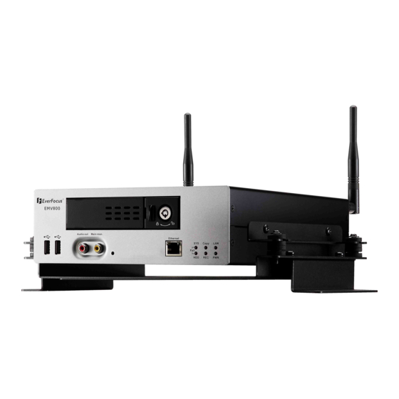
Page 13: Front Panel
1.4 FRONT PANEL Your primary interaction with your new DVR will be through the Front Panel buttons and their corresponding buttons on the included IR Remote Control. Take a moment to learn where the keys are as the remainder of the manual will refer to them often. Figure 1-1 Front Panel USB 2.0: For connecting USB-Flash-Drive to copy/archive video or for firmware upgrades. - Page 14 ETHERNET: RJ-45 network connection 10/100Mbps Ethernet. There are two LEDs on the LAN jack; Green LED means network is connected, amber LED flickers when data is being exchanged. System Status LEDs: Indicators system status. System fail LED: HDD full, HDD/System Temperature, Fan fail HDD fail LED: HDD power off, HDD failure Copy: This LED ON indicates system is archiving data.
-
Page 15: Rear Panel
1.5 REAR PANEL During initial setup you will be connecting your DVR to multiple input and output devices. This is done through the rear panel. Figure 1-2 Rear Panel ○ 1 Main Monitor Out: Main monitor for live and playback display and on-screen display.(same output as the main monitor out at front panel, no conflict between these 2 outputs, they both can be connected simultaneously) ○... - Page 16 Alarm Input: Connect up to 12/8 alarm inputs, selectable between N.O./N.C. contacts. ○ Alarm Output: N.C or N.O type alarm out (form “C”). ○ RS232 socket: Connect this connector to RS232/RS485 compatible device. ○ GPS Data Input: Connect this connector to GPS receiver via GPS cable. ○...
-
Page 17: System Connection
1.6 SYSTEM CONNECTION Please refer to the following diagrams for the system connections. Note: Monitor and Camera must be purchased separately. -
Page 18: Rear Panel Connector
1.7 REAR PANEL CONNECTOR ALARM RS232/RS485 COM2 485+ 485- COM1 ALARM IN ALM IN1 ALM IN2 GND ALM IN3 ALM IN4 ALM IN5 ALM IN6 ALM IN7 ALM IN8 GND ALM IN9 ALM IN10 GND ALM IN11 ALM IN12 GND VIDEO/AUDIO IN1 VID IN1 VID IN2 VID IN3 VID IN4 AUD IN1 AUD IN2 AUD IN3 AUD IN4... - Page 19 POWER GPS_TX GPS_RX CAM POWER2 CAM POWER1 12V OUT 12V OUT 12V OUT 12V OUT 12V OUT 12V OUT 12V OUT 12V OUT CAM POWER3 12V OUT 12V OUT 12V OUT 12V OUT...
-
Page 20: Installation Of Emv1200/800
1.8 INSTALLATION OF EMV1200/800 The DVR can be mounted horizontally (suspend or support mounted). Support Interface Interface Suspend Show all the possible ways to mount the DVR. Use the two Z-brackets supplied to mount it in any ways shown. Support EDSR40 Support... - Page 21 Quick Installation Guide Unpack Everything Make sure you have everything you need before you begin the installation. Equipment Required The following tools may help you to complete the installation: ‧Drill ‧Screwdrivers ‧Wire cutters Choosing the Location Choose a location for installation that: ...
- Page 22 Possible Installation Locations Inside the Automobile Vehicle: Truck Glove box (inside or underneath) Drive seat (between seat and wall) or Passenger seat (underneath) (Users are suggested to use “support” for mounting option) Show the wiring on the wiring harness that connects to the electrical system. ...
- Page 23 Possible Installation Locations Inside the Automobile Vehicle Glove box (inside or underneath) Trunk (Users are suggested to use “suspend” for mounting option) Passenger seat (underneath) Drive seat (between seat and wall) Show the wiring on the wiring harness that connects to the electrical system. ...
- Page 24 Installing the Camera(s) and Monitor The DVR is typically connected to one camera installed inside the car. Other camera(s) can also be installed in different locations (for example, use the waterproof camera to the outside of vehicle). For installation procedure, please refer to the guide that came with the camera(s) you purchased. The Monitor power supply connects from the Automotive adapter (cigarette plug) Monitor and cameras must be purchased separately.
- Page 26 Yellow Cable Red Cable Black Cable Orange Cable Actual power connector for EMV1200/800 Two 12Volt (Red) cables and two GND (Black) cables will be provided. You MUST connect your two 12Volt (Red) cables to either power switch or car’s power interface. Yellow cable is IGN (ignition) and Orange cable is for additional DC 12Volt output, 1Ampere.
- Page 27 Recommendation 1: To reduce vibration during movement, you can Pulling Hot Glue fixe it to DVR and leave a gap so that the cables will not be stretched. Pulling Vibration Recommendation 2: You can apply hot glue to reinforce the connection and to avoid accidental pulling.
-
Page 28: Video Inputs/Outputs Installation
1.9 VIDEO INPUTS/OUTPUTS INSTALLATION Cameras and CCTV monitors must use copper center conductor/copper braid 75 Ohm video cable (e.g. RG-59, RG-6, RG-11) with BNC connectors. To avoid impedance mismatch and undesired loss/reflections, 50 Ohm coax cable (e.g. RG-58), or 75 ohm foil shield antenna cable and other types of coaxial cable are not compatible. -
Page 29: Alarm Input Contacts
1.11.1 Alarm Input Contacts This DVR provides one alarm input per camera. All inputs are programmable N.O. (Normal Open) or N.C. (Normal Closed) Inputs have to be switched by dry contacts. Alarm input with N.O. (Normal Open) contact Alarm input with N.C. (Normal Closed) contact in idle state in idle state All settings are programmed in the ALARM menu (Section 0). -
Page 30: Direct Pc Connection Through Crossover Network Cable
1.13.1 Direct PC Connection through Crossover Network Cable The point-to-point connection of DVR and PC requires a crossover (crossed) network cable. This type of connection is ONLY used for direct connection to a single PC. Make sure that the PC is equipped with a 10/100 Mbps compatible network connection. -
Page 31: Final Install Process
Pinout of straight patch cable 1.14 FINAL INSTALL PROCESS Once you have completed the basic wiring connections, you are ready to turn on the DVR. Simply plug in the power source. The POWER LED will light up if power is normal. Once the system has finished loading, you can begin to set up the menu options for the DVR. -
Page 32: Mouse Operation
Chapter 2 MOUSE OPERATION EMV1200/800 mobile DVRs support 2 sources to control the DVR. It can be controlled with a mouse and the handheld IR remote control. (For IR remote control, please refer to Appendix C Remote Control) This chapter will cover the basic operation using the mouse. 2.1 GENERAL USB MOUSE OPERATION 2.1.1 How to select a channel 1. -
Page 33: Field Input Options
2. Click on any icon to perform that action. These actions are covered in detail in Chapter 3. 3. Click the button to go to live view. 2.1.3 Field Input Options The following are examples of different types of fields available in the Configuration menu. Textbox: Click on the box and an on- screen keyboard will appear*. -
Page 34: Configuration
Chapter 3 CONFIGURATION This chapter provides information for configuring EMV1200/800. 3.1 CONFIGURATION OF DVR EMV1200/800 can be configured through On Screen Display Playback and Configuration Connect to the “Main Mon” output with a monitor and use the mouse or the remote control to configure menu settings. -
Page 35: On Screen Configuration Menu
Figure 3-2 On-screen Keyboard 3.3 On Screen Configuration Menu 1. To bring up the Main Menu, right-click with the USB mouse to bring up the root menu. Figure 3-3 On-screen Configuration 2. Left-click on the “Playback” icon “ ” to enter the Playback Menu. A Playback Bar appear as shown below:... -
Page 36: Search
Playback Bar Name Description Layout TheEMV1200/800 DVR has several display modes available. Click on the desired layout choice Display mode Press to show camera information, press again to show network, HDD, GPS information. Press again to hide all information. Audio Press to cycle through Audio 1, 2,3,4 or no audio Fast Rewind Press to start fast reverse playback... -
Page 37: Time Search
3.4.1 Time Search Figure 3-4 Search Menu – Time Search Play From: Select the time to begin the search by choosing the Date and Time. Click on the “Play” button to start the search. The DVR will automatically begin to play the video selected. The DVR will play the nearest time if there is no data at the selected time. -
Page 38: G Sensor Search
3.4.2 G Sensor Search Click button to start G Sensor search. Figure 3-5 Search Menu – G-Sensor Search From: Select starting date and time To: Select ending date and time. Select search format from Less Than, More Than, Inside Range and Outside Range. Value: Set the G-sensor value to be searched. -
Page 39: Gps Speed Search
3.4.3 GPS Speed Search Click button to enter GPS search menu. Figure 3-6 Search Menu – GPS Search From: Select starting date and time To: Select ending date and time. Display Unit: If the speed is being recorded from the GPS receiver, the desired speed display units must be selected. - Page 40 Figure 3-7 Search Menu – GPS Bordering Search From: Select starting date and time To: Select ending date and time. GPS Border Type: Set GPS border type, select either circle or rectangle. Search Mode: Select if searching Inside or Outside the border. Center Lat.: Set the latitude if border type is circle.
-
Page 41: Event Search
3.4.4 Event Search Click button to enter Event search menu. Figure 3-8 Search Menu – Event Search From: Select starting date and time To: Select ending date and time. Camera: Select which cameras to include in the search. Event: Select which event type(s) to search for. Choose from Alarm or Video Loss. Click on the button to start searching. - Page 42 Figure 3-9 Search Menu – Event List Prev Page: Go to previous page Next Page: Go to next page Play: Playback selected item Delete: Delete selected item Click button to return to the previous level of menu. Click button to enter G Sensor search menu. Click button to enter GPS search menu.
-
Page 43: Archive (Usb)
3.5 ARCHIVE (USB) Right-click to bring up the Root menu, select Playback and click to enter Archive Menu. Figure 3-10 Archive Menu Camera: Select which cameras will be archived. Choose “Select All” to select all the cameras. Player: Check the box to include the ePlayer program as part of the copy (recommended). Start Date/Time: Select the starting date/time to be archived. -
Page 44: Zoom
3.6 Zoom 1. Make sure no camera is in playback mode 2. Select one camera 3. Right-click to bring up the Root menu, select Playback and click to enter Zoom Menu. 4. Select Zoom X 2 or Zoom X4 by clicking on or click to exit from Zoom menu. -
Page 45: Dvr Configuration
Chapter 4 DVR CONFIGURATION This chapter will walk you through the DVR Menu Settings step by step and show you how to set the DVR for your specific application. 4.1 Configuration Menu 1. To bring up the Main Menu, right-click with the USB mouse to bring up the root menu. Figure 4-1 Root Menu 2. - Page 46 Figure 4-2 Configuration Menu...
-
Page 47: Camera Setting
4.2 CAMERA SETTING Figure 4-3 is a screenshot of the CAMERA SETTING MENU. This menu is used to configure individual camera settings. Figure 4-3 Camera Settings-Normal 4.2.1 Normal No.: Camera number. Speed: Frame rate in frames (images) per second (FPS) for continuous recording. The speed is limited by the maximum total recording capacity of the DVR as allocated across all the installed cameras, with an upper limit of 30 FPS (NTSC –... - Page 48 FPS rate in response to a motion or alarm event (see next item). Since EverFocus DVRs have the capability to change recorded image size and FPS rate in response to events, it may be advisable to reserve some recording capacity for event response. For example:...
-
Page 49: Video Loss
4.2.2 Video Loss Figure 4-5 Camera Settings-Video Loss Camera: Select the camera you wish to configure, “Title” will change to the title name of the selected camera. Enable: Check box to enable Video Loss detection. Alarm Output: This will transmit a signal through the alarm output relay. It can be set to either “NONE” (not active), “1”... - Page 50 Network Alarm: Check this box to send out a network alarm to a client PC when motion occurs. (This feature requires PowerCon software on the client PC and proper settings for the Alarm Server in the Network Setup menu; see Section 4.7.6 Alarm Server for more information.) Apply To: This button can be used to copy the video loss settings to other cameras.
-
Page 51: Alarm
4.2.3 Alarm Figure 4-6 Camera Settings-Alarm Speed: Maximum desired frame rate in frames per second (FPS) for event recording; if more than one camera requires simultaneous event recording, the total for all cameras cannot exceed the maximum available FPS for the DVR at the corresponding resolution setting, and the available FPS may be divided across the cameras responding to an event. -
Page 52: Record Setting
4.3 RECORD SETTING Figure 4- is a screenshot of the RECORD SETTING MENU. This menu is used to configure basic recording settings. Figure 4-7 Record Settings 4.3.1 Record Record Overwrite: Check the box and the disk will begin overwriting when full. NOTE: Unless this box is checked, THE DVR MUST STOP RECORDING WHEN THE DISK IS FULL. -
Page 53: Alarm/Gps
4.4 ALARM/GPS Figure 4- is a screenshot of the ALARM/GPS SETTING MENU. This menu will guide you through alarm and GPS setup. Figure 4-8 Alarm/GPS - Alarm 4.4.1 Alarm-Alarm Settings Figure 4-9 Alarm – Alarm Settings... - Page 54 Alarm: Select the alarm input trigger connection number from 1 to 12 (or 1 to 8). Enable: Check box to enable response to that alarm trigger. Input Type: This field is to change the type of alarm trigger. N.O.: Normal Open contact. N.C.: Normal Closed contact.
-
Page 55: Alarm-Event Settings
4.4.2 Alarm-Event Settings This section covers notifications due to internal system event warnings. Figure 4-10 Alarm – Event Settings Event: Select from the following event types. Fan Failure: Fan is not working. HD Temperature: Hard drive is over the safety warning temperature. HD Failure: If DVR fails to detect the HDD on start up, the system will create an HD failure event. - Page 56 Fan Failure: Figure 4-11 Alarm – Event – Fan Failure Buzzer: Check box to enable buzzer when fan is not working. Email Notify: Check box to enable email notification when fan is not working. Email operation requires that valid email settings have been entered in the Network Setting/Email setup screen. Network Alarm: Check box to send out a network alarm to client PC.
- Page 57 HD Temperature: Figure 4-12 Alarm – Event - HD Temperature Buzzer: Check box to enable buzzer when hard drive’s temperature is over the “Temp. Warning Limit”. Email Notify: Check box to enable email notification when HDD temperature is over the “Temp. Warning Limit”.
- Page 58 HD Failure: Figure 4-13 Alarm – Event - HD Failure Buzzer: Check box to enable the buzzer if no hard drive is detected on system startup. Email Notify: Check box to enable email notification function when HD fails. Email operation requires that valid email settings have been entered in the Network Setting/Email setup screen.
- Page 59 HD Full: Figure 4-14 Alarm – Event - HD Full Buzzer: Check box to enable the buzzer when hard drive is full (recommended if the Record Overwrite function is disabled, see Section 4.3). Email Notify: Check box to enable email notification when HD is full. Email operation requires that valid email settings have been entered in the Network Setting/Email setup screen.
- Page 60 HD Off: Figure 4-15 Alarm – Event - HD Off Buzzer: Check box to enable buzzer if the hard drive is turned off (disconnected) or becomes disabled (cannot be detected by the system). Email Notify: Check box to enable email notification when HD is off. Email operation requires that valid email settings have been entered in the Network Setting/Email setup screen.
- Page 61 Power Loss: Figure 4-16 Alarm – Event – Power Loss Email Notify: Check box to enable email notification when power has been restored. Email operation requires that valid email settings have been entered in the Network Setting/Email setup screen. Network Alarm: Check box to send out a network alarm to client PC when power has been restored. (requires PowerCon software and setting up Alarm Server in Network Setup menu) NOTE: As alarms and emails cannot be transmitted without power, the log entry is made when power is restored, and any notifications cannot be made until that time.
- Page 62 Network Loss: Figure 4-17 Alarm – Event – Network Loss Buzzer: Check box to enable buzzer when network is lost. Alarm Output: This will transmit a signal through the alarm output relay. It can be set to either “NONE” (not active), “1”...
- Page 63 GPS Loss: Figure 4-18 Alarm – Event – GPS Loss Buzzer: Check box to enable buzzer when GPS is lost. Email Notify: Check box to enable email notification when GPS is lost. Email operation requires that valid email settings have been entered in the Network Setting/Email setup screen. Network Alarm: Check box to send out a network alarm to client PC.
-
Page 64: Alarm - Video Loss
4.4.3 Alarm – Video Loss Figure 4-19 Alarm – Video Loss Camera: Select the camera you wish to configure, “Title” will change to the title name of the selected camera. Enable: Check box to enable Video Loss detection. Alarm Output: This will transmit a signal through the alarm output relay. It can be set to either “NONE” (not active), “1”... - Page 65 Network Alarm: Check this box to send out a network alarm to a client PC when video loss occurs. (This feature requires PowerCon software on the client PC and proper settings for the Alarm Server in the Network Setup menu; see Section 4.7.6 Alarm Server for more information.) Apply To: This button can be used to copy the video loss settings to other cameras.
-
Page 66: Alarm-G-Sensor Settings
4.4.4 Alarm-G-Sensor Settings Figure 4-20 Alarm – G-Sensor G-Sensor: Select On to enable G-Sensor function. Select Off to disable G-Sensor function. XY Axial Trigger Value: Set XY Axial trigger value, alarm will be triggered when acceleration reaches this value in horizontal direction with respect to the horizon. Z Axial Trigger Value: Set Z Axial trigger value, alarm will be triggered when acceleration reaches this value in vertical direction with respect to the horizon. -
Page 67: Alarm-Gps Speed
4.4.5 Alarm-GPS Speed Figure 4-21 Alarm – GPS Speed Speed Unit: If the speed is being recorded from the GPS receiver, the desired speed display units must be selected. Select GPS speed unit from KPH and MPH. Selecting MPH converts the GPS signal to display speed in miles per hour. -
Page 68: Alarm-Gps Event Action
4.4.6 Alarm-GPS Event Action Press to enter GPS Event Action Menu. Figure 4-22 Alarm – GPS Event Action Alarm Output: This will transmit a signal through the alarm output relay. It can be set to either “NONE” (not active), “1” (active) or “2” (active). Output Type: Output action when alarm is triggered. -
Page 69: Alarm-Gps Fencing
4.4.7 Alarm-GPS Fencing Press to enter GPS Fencing Menu. Figure 4-23 Alarm – GPS Fencing GPS Alarm: Select “On” to enable GPS alarm. Select “Off” to disable GPS alarm function. GPS Border Type: Set to a circle or rectangle and dynamic prompts for Latitude and Longitude appear. Center Latitude: Set the latitude if border type is circle. -
Page 70: Date/Time Setting
4.5 Date/Time Setting Figure 4-24 is a screenshot of the DATE/TIME SETTING MENU. This menu is for setting up the date/time parameters for the DVR. Figure 4-24 Date/Time Settings 4.5.1 Date/Time Settings Time Zone: Set the time zone that the DVR adjusts to when updating from the time server. Date: Set current Date. -
Page 71: Daylight Saving
c) In the DOS Prompt, type “ping pool.ntp.org” to find out the IP address of an NTP Server. If selecting “GPS”, you will be able to do the following setting: Update Interval: The frequency that the system automatically updates the time via the NTP server. Select Daily, Weekly, or Monthly. -
Page 72: Display
4.6 Display Figure 4-26 is a screenshot of the DISPLAY SETTING MENU. This menu will walk you through the Main Monitor On-Screen Display (OSD) and Main Monitor Sequential setup. Figure 4-26 Display Settings 4.6.1 Title Main Title: Input the main title by using the on-screen keyboard. Maximum text length is 16 characters. Camera 1~8: Input camera name for camera 1~8 by using the on-screen keyboard. - Page 73 Figure 4-27 Display-OSD Main Monitor Main Title: Check the box to display main title. Camera Title: Check the box to display camera titles for main monitor. Date/Time: Check the box to display current date/time. Playback Date/Time: Check the box to display playback date/time. Playback Status: Check the box to display playback status.
-
Page 74: Layout
4.6.3 Layout Click button to set up Layout parameters. Figure 4-28 Display-Layout Main Monitor Display Switch: Select display switch for main monitor from 1 UP, 4 UP, 9 UP, 12 UP(EMV1200) and SEQ. X Up Type: Select layout type for the display switch. For 12 Up, the channel number selected will be shown in the first display. -
Page 75: Sequence
4.6.4 Sequence Click button to set up Sequence parameters. Figure 4-29 Display-Sequence Step: Sequence order. For reference. Camera: Select which camera appears in the current step. Dwell (sec): Set the dwell time for each step. Sequence dwell time can be set from 0 to 99 seconds. Sequence repeats continuously from steps 1 through 20 until interrupted. -
Page 76: Network Setting
4.7 NETWORK SETTING Figure 4-30 is a screenshot of the NETWORK SETTING MENU. This menu is for configuring the DVR for a network connection. NOTE: Since every Network Configuration is different, please check with your Network Administrator or ISP to see if your DVR should use specific IP addresses and/or port numbers. Figure 4-30 Network Menu 4.7.1 LAN Settings Figure 4-31 Network Menu –... - Page 77 Network Type: Static IP: User can set a fixed IP for network connection. DHCP: DHCP server in LAN will automatically an assign IP configuration for the network connection IP address: This field shows the DVR’s current IP Address. A static IP address must be set manually. If DHCP or PPPoE is selected, this value will be assigned automatically.
- Page 78 2. If you are connecting through a router, make sure that you have ‘opened up’ all the required network ports in the port forwarding section of your router’s setup options. That is, you have directed the router to send any incoming traffic using those IP ports to the LAN IP address of the DVR. Useful information about router port forwarding can be found at www.portforward.com .
-
Page 79: Wireless Settings
4.7.2 Wireless Settings Figure 4-32 Network Menu – Wireless Wireless Mode: Select wireless mode from Static IP, DHCP or disabled. IP address: This field shows the DVR’s current IP Address. A static IP address must be set manually. If DHCP or PPPoE is selected, this value will be assigned automatically. Subnet Mask: This field shows the subnet mask for your network so the DVR will be recognized within the network. -
Page 80: Mobile Connection Settings
4.7.3 Mobile Connection Settings Figure 4-33 Network Menu – Mobile Connection GPRS Service: Select “On” to enable GPRS service. Select “Off” to disable GPRS function. APN (Access Point Name): By local ISP setting. Phone Number: Input the phone number to dial for mobile connection. User Name: Input the user name required for mobile connection. -
Page 81: Email Settings
4.7.4 Email Settings Figure 4-34 Network Menu – Email Settings SMTP Server: Assign the SMTP (e-mail) server’s name. NOTE: For more reliable email service, use the server’s IP address. SMTP Port: Assign the port number used by the SMTP server. Authentication: Check this box if the SMTP server requires authentication (user name / password). -
Page 82: Ddns Settings
“Success”. You should now be able to connect by typing in the host name you created. Example: http://hostname.everfocusddns.com It is not necessary to append the HTTP port number to the DDNS name. The EverFocus DDNS server not only keeps track of your DVR’s IP address, it keeps track of the ports too! - Page 83 Host name: Host name created through the dyndns account. User name: User name of the dyndns account. Password: Password of the dyndns account. Note: For more details on DDNS setup, please see “Chapter 7 - Everfocus DDNS Setup”. Click button to return to the previous level of menu.
-
Page 84: Alarm Server Settings
4.7.6 Alarm Server Settings Figure 4-37 Network Menu – Alarm Server This menu defines the parameters for communicating with a PC. Server IP1~3: IP address of client PC. The network alarm can be transmitted to up to 3 addresses. Protocol: Select the protocol type for alarm transmission: UDP: User Datagram Protocol TCP: Transmission Control Protocol Port: Select the transmission port for network alarm messages... -
Page 85: Meta Server Settings
4.7.7 Meta Server Settings Figure 4-38 Network Menu – Meta Server Meta Server is the server to send out GPS Data or G-Sensor Data to Central Management Software server. Data Type: Select the data type from GPS Data and G-Sensor Data. Check the “Send GPS/G-Sensor Data to Remote Server”... -
Page 86: Network Test
4.7.8 Network Test Figure 4-39 Network Menu – Network Test Test Server Address: Enter the server address to be tested. Click button to start testing the network connection. -
Page 87: Remote/Mobile
(IP Cameras from iPhone/Android/Blackberry and Nokia) by http browser. The "MobileFocus” by EverFocus allows you to connect to your EverFocus DVRs and IP Cameras from your smart phone. With MobileFocus, you can view video streams and control the PTZ cameras easily. -
Page 88: System
4.8 SYSTEM 4-39 is a screenshot of the SYSTEM MENU. This menu is for setting up the general system parameters for the DVR. Figure 4-41 System Menu 4.8.1 User User Menu is where you can add or delete different login IDs on the system as well as set access levels. See the charts below for a listing of the rights associated with each access level. - Page 89 Click “Add” button to add a new user. Set the name (case-sensitive), password, access level and status. Press “Add” button to confirm a new user or “Cancel” to exit without making changes. Figure 4-41 System-User-Add Edit Click “Edit” button to make changes to an existing user account. Press “Save” button to save changes or “Cancel”...
- Page 90 There are three system access levels. The following charts show the rights of each level. Local Local Admin User Guest Live View Copy Playback Camera Record Alarm/GPS Date/Time Configuration Display Network System Information Admin User Guest Live View Copy Search & Playback Camera Record Alarm/GPS...
-
Page 91: I/O Control
4.8.2 I/O Control Figure 4-43 is a screenshot of the I/O Control Setting Menu. This menu is used to define the settings for controlling the DVR through RS485, and for DVR control of attached PTZ cameras. Figure 4-43 System-I/O Control-RS232 Select Bus Name from RS-232 and RS-485. - Page 92 PTZ Protocol: Select PTZ protocol, choose from the following protocols: Transparent, Pelco D, Pelco P, or Everfocus. (NOTE: all cameras on the bus must use the same protocol) 485 ID: This is the ID used by the EKB500 to send commands to the DVR. On an RS485 connection, every device (PTZ, DVR and controller) must be assigned a unique ID number between 0 and 127.
-
Page 93: Disk
4.8.3 DISK Figure 4-45 is a screenshot of the DISK MENU. This menu is used to review the DVR’s hard drive settings and status. No values in this screen can be changed by the operator. Figure 4-45 System-Disk Record Time (Start): Shows earliest recorded time on the DVR. Record Time (End): Shows latest or most current recorded time on the DVR. -
Page 94: Log
4.8.4 LOG Figure 4-46 System-Log This screen is used to choose, display and/or export log entries. From Date: Select starting date of log to be displayed. Time: Select starting time of log to be displayed. Date: Select end date of log to be displayed. Time: Select end time of log to be displayed. - Page 95 View Log: Press button to view the log. See Figure 4-46 for more detail. Clear Log: Press button to clear the log. Export Log to USB: Press button to export log data to USB. Figure 4-47 Log List Prev Page: Go to the previous page of log. Next Page: Go to the next page of log.
-
Page 96: Settings
4.8.5 SETTINGS Figure 4-48 System-Settings Audio Output Channel: Select audio output channel. Language: Choose which language the DVR uses. The available languages may vary based on region. User Login: Check this box to require user login for menu access from the front panel. When this is disabled, no username or password is required to access the system from the front panel, and all users operate with ADMIN rights from the front panel. -
Page 97: Service
4.8.6 SERVICE Figure 4-49 System-Service. Firmware Current Firmware Version: Displays the current version. Upgrade from USB: Press “Upgrade” to upgrade the firmware. NOTE: To perform a Firmware Upgrade, you will need to connect a USB flash device with the desired firmware. Do not disconnect the USB device or turn off the power to the unit during the upgrade;... -
Page 98: Information
4.9 INFORMATION Figure 4.50 is a screenshot of the INFORMATION MENU. This menu displays important (read only) system information. Figure 4-50 Information System Version: Displays firmware version number. Model: Displays DVR model number. NTSC/PAL: Displays current video format selected based video format on Camera 1 input at boot up. Status Disk: Displays status of the installed disk(s);... -
Page 99: Networking Overview
Chapter Networking Overview This chapter will give you a basic instruction on how to set up the DVR for network connection. It is highly recommended that you have a working knowledge of what a network is and how it works. This will be helpful in completing the networking process. -
Page 100: Virtual Ports
There are many types of high speed Internet available. The most common ones are T1, Cable, and DSL (in order of speed). The DVR is not compatible with a dial-up connection. Note: EverFocus suggests having a minimum upload speed of 256KBps. This can be addressed by your Internet Service Provider. -
Page 101: What Is Your Network Setup
This makes it much simpler to host a website, email server, or other type of server connection. Everfocus suggests using a static IP address. If this is not available, you will need to use a dynamic IP address. This is explained below. -
Page 102: Simple One To One Connection
2. Direct High Speed Modem Connection: A direct modem connection uses a standard network cable to connect the modem directly to a computer (or in this case a modem to the DVR). This type of connection only covers single-port modems. For a combination modem/router, use the setup described below. - Page 103 Once you have a cross-over cable plug one end into the LAN port on the back of the DVR and the other into the network card on the back of the computer. Log into the EverFocus DVR menu and go to the Network Setting Menu. You must use the Static IP option for this type of connection.
- Page 106 Click on the option that says “Use the following IP address” Assign an IP address of 192.168.1.2, a Subnet Mask of 255.255.255.0, and a Default Gateway of 192.168.1.1, then click OK. Restart both the computer and the DVR. ...
-
Page 107: Direct High Speed Modem Connection
5.8 Direct High Speed Modem Connection Straight Through Ethernet Cable Pin outs: The Figure below shows the pin configurations for a straight cable. Connection Procedure: The first step is to purchase or make a straight through cable. We recommend purchasing one if you have never made a straight through cable. - Page 108 Log into the EverFocus DVR menu and go to the Network Setting Menu. Input the Static IP address, the Subnet Mask, and the Gateway that you obtained from the internet service provider. Note: If you have a dynamic IP address, you can set the DVR to DHCP to automatically detect the network settings.
-
Page 109: Router Or Lan Connection
5.9 Router or LAN Connection Straight Through Ethernet Cable Pin outs: The Figure below shows the pin configurations for a straight cable. Connection Procedure: The First step is to purchase or make a straight through cable. We recommend purchasing one if you have never made a straight through cable. - Page 110 Once you have a straight through cable plug one end into the LAN port on the back of the recorder and the other into the router. Log into the EverFocus DVR menu and go to the Network Setting Menu. To let the router automatically assign an address: ...
- Page 111 number of the IP address. For example, if the IP address of the computer is 192.168.2.101, the DVR’s IP address should be 192.168.002.050. To access the DVR from a computer simply open Internet Explorer and in the address bar type: http:// (IP address of the DVR) Note: The DVR’s IP address will only work at the location of the DVR.
-
Page 112: Remote Operation From Browser
Chapter 6 REMOTE OPERATION FROM BROWSER 6.1 CONNECTING TO EMV1200/800 To access the DVR from a computer, open an Internet Explorer window and in the address bar type: Local connection: http:// (IP address from the DVR’s Network Menu): IP port used e.g. -
Page 113: Browser Security Setting
The default user name is “admin”. The default password is “11111111”. Click on the Login button and you will log in to the recorder’s Network Viewer. 6.2 BROWSER SECURITY SETTING 6.2.1 Installing ActiveX controls When you first connect to the DVR’s IP address, you should see a screen like the one below. If you do not see a yellow bar like the one the arrow is pointing at, your security settings may be too high. - Page 114 Once the file finishes installing, you will return to the screen like the one below.
- Page 115 Right click on the yellow bar and select “Run Add-on…” Install the MSXML file when prompted to do so. Now, you will able to see the remote live page.
-
Page 116: Enabling Activex Controls
6.2.2 Enabling ActiveX Controls Note: This section is only necessary if you DO NOT see the yellow ActiveX bar at the top of your browser screen when you first connect to the DVR. At the top of the Internet Explorer Window, click on Tools, then select Internet Options. Click the Security tab at the top of the window, then choose Custom Level near the bottom. - Page 117 In the Security Settings window, scroll to “ActiveX controls and plug-ins” Set the controls as follows: “Enable”: Allow previously unused ActiveX controls to run without prompt (Internet Explorer 7 only) Allow scriptlets (IE7 only) Automatic prompting for ActiveX controls ...
- Page 118 Close the window so you are back at the login screen. Click the Refresh button to reload the page. Install the ePlusDVR.cab file when prompted to do so. Once the file finishes installing, you will return to the same login page as before. Type in the user name and password and click Login to view the cameras.
-
Page 119: Gremote Live View
6.3 GREMOTE LIVE VIEW 1. Click on a camera number on the left side of the display to switch that camera to full screen. Click on “4UP” to display 4 screens, click on “9UP” to display 9 screens or click on “13UP” to display 12 screens. (“13UP”... - Page 120 Alarm/Event Setup Date/Time Setup Display Setup Network Setup System Setup Information Setup Copy Menu Search Menu 5. In the main page, you will see live images in a 13-screen display (or 4 or 9 screens, depending on the display setting).
-
Page 121: Remote Playback
6.4 REMOTE PLAYBACK To playback the video, click the “Search” button. Select from “Time Search”, “Event Search”, or “Motion Search”. For more details about Search setting, please refer to “3.4 Search Setting”. “Event Search” and “Motion Search” will show maximum 400 search result items (beginning with the start time) Back: returns to live view Playback Control Keys... -
Page 122: Everfocus Ddns Setup
Chapter 7 EVERFOCUS DDNS SETUP Setup Steps: Step 1. Set up the Network Menu according to the instructions detailed in the Networking chapter. (Make sure that DNS Server 1 is set correctly or DDNS will not work) Step 2. Go to the website http://everfocusddns.com and check for an available name. - Page 123 Step 5. You should now be able to connect by typing the name you created into the address bar. Example: http://hostname.everfocusddns.com It is not necessary to append the HTTP port number to the DDNS name. The EverFocus DDNS server not only keeps track of your DVR’s IP address, it keeps track of the ports too!
-
Page 124: Linksys & D-Link Port Forwarding
Chapter 8 LINKSYS & D-LINK PORT FORWARDING 8.1 TYPICAL LINKSYS PORT FORWARDING This section will cover a few simple configurations for the Linksys router. This chapter is only to offer some help to the installer and end user. Please understand we DO NOT support this product and will not give tech support on it. - Page 125 Applications and Gaming allows you to set up public services on your network, such as web servers, ftp servers, e-mail servers, or other specialized Internet applications. (Some Internet applications may not require any forwarding) To forward a port, enter the information on each line for the criteria required. Descriptions of each criterion are described here.
-
Page 126: Typical D-Link Port Forwarding
8.2 TYPICAL D-LINK PORT FORWARDING This section will cover a few simple configurations for the D-Link router. This chapter is only to offer some help to the installer and end user. Please understand we DO NOT support this product and will not give tech support on it. - Page 127 Click Virtual Servers on the left to bring up the following screen. Virtual Servers allows users who are connecting remotely to access services on the router’s Local Network. The functions of each field are described below. Virtual Server - Select Enabled or Disabled Name - Enter the name referencing the virtual service Private IP - The IP address of the device running the local services.
- Page 128 Here is an example of the information for each service: Name Private IP Protocol Private Port Public Port Schedule HTTP 192.168.1.50 Both Enable Where 192.168.1.50 is the IP address of the EMV1200/800 on the LAN, and the default port 80 is in use. Note: If you changed port 80 in the DVR’s Network Menu, open that port instead of 80.
-
Page 129: Troubleshooting
Chapter 9 TROUBLESHOOTING If you have problems with the system, run through the following checklist to see if you can solve the problem. The DVR will not go into record mode. Bring up the DVR’s Menu and check under the Camera Menu. Verify that all connected cameras ... - Page 130 Make sure you are using the correct WAN IP address given by the ISP, or, if you have a Dynamic IP, check if the IP address has changed; use DDNS to avoid problems caused by changing ISP addresses.
-
Page 131: Appendix A: Timing Of Alarm Modes
Appendix APPENDIX A: TIMING OF ALARM MODES Transparent Mode Input Event Alarm Duration Event = Reaction Duration of alarm input source (motion, contact, system events...) Event Resulting duration for this alarm mode, related to event record, alarm outputs, OSD message, reaction buzzer Timeout + Transparent Mode... - Page 132 Timeout Mode Input Event Alarm Duration Event Duration = Reaction Duration of alarm input source (motion, contact, system events...) Event Alarm duration for timeout, defined in the event setup menus Duration Resulting duration for this alarm mode, related to event record, alarm outputs, OSD message, reaction buzzer Permanent Mode...
- Page 133 Timeout Mode: Retrigger of Alarms Duration of alarm input source (motion, contact, system events...) Event Alarm duration for timeout, defined in the event setup menus Duration Resulting duration for this alarm mode, related to event record, alarm outputs, OSD message, reaction buzzer Timeout+Transparent Mode: Retrigger of Alarms...
-
Page 134: Appendix B: Express Setup Recording Value Selection Rules
Appendix APPENDIX B: EXPRESS SETUP RECORDING VALUE SELECTION RULES Case 1: Record Mode: Normal + Event Record With: Recording days The DVR will Auto adjust image Quality and Event frame rate to match the number of Recording days which user selected: According to resolution, event hours and other assumptions above, the DVR will attempt to select one set of suitable quality and event frame rate by checking if set 1 meets the requirements, and proceed in order unit the requirements are met. - Page 135 Case 3: Record Mode: Normal + Event or Event Only Record With: Preset Setting DVR will apply the settings in the table below to all cameras according to the Preset Settings. Preset Setting Option Camera Item Apply value Quality Superior Best Quality Normal Frame Rate Max recording frame rate of DVR Event Frame Rate...
-
Page 136: Appendix C: Remote Control
Appendix APPENDIX C: REMOTE CONTROL The IR remote control is an accessory to enhance the convenient operation of the DVR. You can perform all the settings and operations from the remote control. The effective distance is up to 33 feet line of sight. - Page 137 Croydon Surrey, CR0 4WD, UK Tel: +44-20-8649-9757 Fax: +44-20-8649-9907 www.everfocusuk.co.uk basil@everfocusuk.co.uk Ihr EverFocus Produkt wurde Your EverFocus product is designed entwickelt und hergestellt mit qualitativ and manufactured with high quality hochwertigen Materialien und materials and components which can Komponenten, die recycelt und wieder be recycled and reused.
Need help?
Do you have a question about the EMV1200 and is the answer not in the manual?
Questions and answers