Table of Contents
Advertisement
Quick Links
SHERWOOD INDUSTRIES IS AN ENVIRONMENTALLY RESPONSIBLE COMPANY. THIS MANUAL IS PRINTED ON RECYCLED PAPER.
PLEASE KEEP THESE INSTRUCTIONS FOR FUTURE REFERENCE
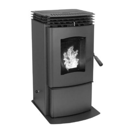
PELLET STOVE
Mini
TECHNICAL MANUAL
PLEASE READ THIS ENTIRE MANUAL BEFORE INSTALLATION AND USE
OF THIS PELLET BURNING ROOM HEATER. FAILURE TO FOLLOW THESE
INSTRUCTIONS COULD RESULT IN PROPERTY DAMAGE, BODILY INJURY
OR EVEN DEATH
Contact your building or fire officials about restrictions and installation
inspection requirements in your area.
50-1221
Advertisement
Table of Contents

Related Manuals for Enviro C-10985


Summary of Contents for Enviro C-10985
- Page 1 SHERWOOD INDUSTRIES IS AN ENVIRONMENTALLY RESPONSIBLE COMPANY. THIS MANUAL IS PRINTED ON RECYCLED PAPER. PLEASE KEEP THESE INSTRUCTIONS FOR FUTURE REFERENCE PELLET STOVE Mini TECHNICAL MANUAL PLEASE READ THIS ENTIRE MANUAL BEFORE INSTALLATION AND USE OF THIS PELLET BURNING ROOM HEATER. FAILURE TO FOLLOW THESE...
-
Page 2: Table Of Contents
Introduction...3 Rating Label Location...3 Important Safety Data...3 Safety Warnings And Recommendations...3 Installation...5 Deciding Where to Locate your Pellet Appliance...5 Removing Pellet Stove From Pallet...5 Appliance Dimensions and Specifications...6 Hearth Pad (50-1219) Installation...6 Clearances to Combustibles...7 Alcove Clearances...7 Vent Termination Requirements...8 Outside Fresh-Air Connection...9... -
Page 3: Introduction
To prevent the possibility of a fire, ensure that the appliance is properly installed by adhering to the installation instructions. An ENVIRO dealer will be happy to assist you in obtaining information with regards to your local building codes and installation restrictions. - Page 4 GLASS: Do not abuse the glass by striking or slamming the door. Do not attempt to operate the stove with broken glass. The stove uses ceramic glass. Replacement glass must be purchased from an ENVIRO dealer. Do not attempt to open the door and clean the glass while the unit is in operation or if glass is hot.
-
Page 5: Installation
An interior vent can be used with approved pipe passing through the ceiling and roof. 5. Locate the stove in a large and open room that is centrally located in the house. This will optimize heat circulation. 6. The power cord is 8 feet (2.43 m) long and may require a grounded extension cord to reach the nearest electrical outlet. -
Page 6: Appliance Dimensions And Specifications
3. Locate the five (5) screw holes (see Figure 3) and install #8-32 torx T-20 screws and tighten. 4. Adjust the leveling legs to level and support stove. 5. Re-install the cab sides and ash pan cover. Installation PECIFICATIONS "... -
Page 7: Clearances To Combustibles
LEARANCES TO OMBUSTIBLES IMPORTANT: Attach the Mini’s Hearth Pad when installing the unit on a combustible floor. The supplied hearth pad meet all the requirement of a proper hearth pad. If you do not use the supplied hearth pad a hearth pad must be used when on combustible material. -
Page 8: Vent Termination Requirements
ERMINATION EQUIREMENTS IT IS RECOMMENDED THAT YOUR PELLET STOVE BE INSTALLED BY AN AUTHORIZED DEALER/INSTALLER. Table 1: Use in conjunction with Figure 6 for allowable exterior vent termination locations. Letter Minimum Clearance 24 in (61 cm) 48 in (122 cm) -
Page 9: Outside Fresh-Air Connection
UTSIDE RESH ONNECTION Outside fresh air is mandatory when installing this unit in airtight homes and mobile homes. A Fresh-air intake is strongly recommended for all installations. Failure to install intake air may result in improper combustion as well as the unit smoking during power failures. -
Page 10: Mobile Home Installation
CAUTION: THE STRUCTURAL INTEGRITY OF THE MANUFACTURED HOME FLOOR, WALL AND CEILING/ROOF MUST BE MAINTAINED. ORNER HROUGH NSTALLATION Installation electrically ENVIRO Mini Optional Hearth Pad Flooring Steel Frame Figure 9: Mobile home installation. 3" (75mm) 3" (75mm) Figure 10: Corner Installation. -
Page 11: Horizontal Exhaust Through Wall Installation
2. Install a non-combustible hearth pad (where necessary). 3. Place the appliance 15” (37.5 cm) away from the wall. If the stove is to be set on a hearth pad, set the unit on it, and adjust the leveling legs. -
Page 12: Through Wall With Vertical Rise And Horizontal Termination Installation - Freestanding
• Some horizontal through wall installations may require a “T” and 3 to 5 feet (91 to 152 cm) of vertical pipe outside the building to help naturally draft in the unit. • This may be required if a proper burn cannot be maintained, after the stove has been tested and the airflow set. -
Page 13: Inside Vertical Installations
3. Install ceiling thimble and secure the flashing as you go through the roof. 4. Ensure that the rain cap is approximately 24” (600 mm) above the roof. Installation 1. Choose a stove location that is ideal. See the section “D � �� PPLIANCE ���� ���... -
Page 14: Hearth Mount Installation
�������� �� ����� �� ��������� ����� ����� EARTH OUNT NSTALLATION Flue Connector ��������� ������� ��������� Figure 17: Freestanding hearth mount installation. Figure 18: Freestanding hearth mount installation overview. Installation ������ ������� �� �������� ���� ��� ����� ��� ������ Refer to Figures 17 and 18. �������... -
Page 15: Exterior Mounted Exhaust Blower (20-070)
The Mini can be equipped with an externally mounted exhaust blower. This optional kit includes all components necessary to install the exhaust blower on any vertical wall surface. Choose a location for your stove that meets the requirements stated in your manual and allows installation with the least amount of interference with house framing, plumbing, wiring, etc. - Page 16 YPICAL HROUGH 45°Elbow with Rodent screen or stainless steel termination hood 2ft (610mm) Riser Pipe Adaptor Exterior Blower and Housing Figure 22: Through Wall Installation with Exterior Blower Kit. NOTE: Ensure that all interior vent connections are sealed by placing a small bead of high temperature silicone around each chimney connection.
-
Page 17: Typical Through Wall With Exterior Blower Kit Installation - Vertical Termination
YPICAL HROUGH Follow the previous pages for through wall installations. Ensure that vent pipe is properly secured to wall using wall straps. Maintain clearances to combustibles on vent pipe as well as unit. Roof Sheathing Rain Cap Roof Flashing Roof Rafters Ceiling Joists Vent Pipe Exterior Wall... -
Page 18: Thermostat Installation
Heat Indicator. If the heating load is not great enough when the stove is on low, the high limit switch will turn the stove off and the switch will have to be manually reset. To reset the high limit switch, remove the right cabinet side. -
Page 19: Slider/Damper Set-Up
LIDER AMPER This is used to regulate the airflow through the pellet stove. The slider damper should be set by a trained technician using magnehelic. Figure 28: Slider/Damper Plate in Unit. If the fire should happen to go out and the heat output indicator has been set on the lowest setting, the Slider Damper should be pushed in slightly, decreasing the air in the firebox. -
Page 20: Optional Panel Kit
PTIONAL ANEL This kit must be installed before the unit is started. Tools Required: ●T-20 screwdriver Kit Components: Quantity Description Panel Left Cab Panel Right Cab Hopper Lid #8 T-20 screws (3⁄8” long) Hopper Bracket Bushing 1⁄4” O.D. x 1⁄8” long Please ensure that all components are supplied with this kit. -
Page 21: Fan Kit Installation
3. Install the screw in the bottom hole on both brackets (#3 in Figure 32). 4. Let the hopper lid lay flat on the stove top then tighten the four (4) bracket screws. Figure 34: Behind the left cab panels. -
Page 22: Troubleshooting
DO NOT: ● Service the stove with wet hands. The stove is an electrical appliance, which may pose a shock hazard if handled improperly. Only qualified technicians should deal with possible internal electrical failures. ● Do not remove from the firebox any screws without penetrating oil lubrication. -
Page 23: Wiring Diagram
Troubleshooting üPoor Quality Fuel – Insufficient energy in the fuel to produce enough heat to keep the stove burning or operational. üExhaust Temperature Sensor failure. – Bypass sensor located on Exhaust Blower if stove now operates properly, the unit may require cleaning or a new sensor. Contact your local dealer for service. -
Page 24: Fuses
üSet the auger trim till the #1 and #5 lights are illuminated. If the stove goes out and there are partially burned pellets left in the burn pot liner, the stove has shut down due to a lack of air, exhaust temperature, or power failure. -
Page 25: Wiring Diagram
Wiring Diagram White Black Grey Vacuum Grey Switch Blue White Combustion Blower Brown F (49 Exhaust Temperature Sensor Brown Black White Black Ignitor Purple Convection White Blower Yellow Auger White Motor F (93 Orange High Limit Orange Temperature Sensor Armor Cable Supplied Power Cord Ground... -
Page 26: Parts List
Reference Description Number 120°F (49°C) Ceramic Fan Temperature Sensor Auger Motor - 115V High Limit Temp Sensor 200°F (93°C) Manual Reset Vacuum Switch - 115V Silicone Hose Aluminum Hose Barb Shoulder Bolt, Hardened Bushing & Nut (Set of 2) Combustion Blower motor with mount Auger Brass Bushings (Set of 2) Door Hinge Bracket External Exhaust Back (For Optional Kit) - Page 27 Number Firebox Panel Set with Insulation Side Louver Burn Pot Burn Pot Liner Burn Pot Bottom Front Louvers Lid Set Stove Top Assembly Hopper Guard Handle Bracket Draft Slider Door Assembly Complete Ash Pan Cover Ash Pan Ash Shelf Louver Cabinet Side Left Starter Pipe 3”...
-
Page 28: Parts Diagram - Components
Parts Diagram - Components �� �� � �� �� �� �� � � �� �� � � � � � �� �� Mini - Components April 2005... -
Page 29: Parts Diagram - Steel
Parts Diagram - Steel... -
Page 30: Warranty
Sherwood Industries Ltd. gives a five year limited warranty on all steel manufactured parts. A one-year warranty is provided on all electrical components. The above limited warranties are extended only to the original purchaser. There is no warranty on the following parts: ●... -
Page 31: Installation Data Sheet
INSTALLER’S SIGNATURE: _________________________________________ 6782 OLDFIELD RD. SAANICHTON, BC, CANADA V8M 2A3 NAME OF DEALER: _________________________________________ ADDRESS: _________________________________________ _________________________________________ _________________________________________ PHONE:___________________________________ NAME OF INSTALLER: _________________________________________ (dd/mm/yyyy) ADDRESS: (dd/mm/yyyy) _________________________________________ _________________________________________ _________________________________________ PHONE:___________________________________ MANUFACTURED BY: SHERWOOD INDUSTRIES LTD. www.envirofire.biz October 25, 2005 C-10985...
Need help?
Do you have a question about the C-10985 and is the answer not in the manual?
Questions and answers